Construction of Hazrat Shah Paran - Bangladesh Group of IABSE
Construction of Hazrat Shah Paran - Bangladesh Group of IABSE
Construction of Hazrat Shah Paran - Bangladesh Group of IABSE

Create successful ePaper yourself
Turn your PDF publications into a flip-book with our unique Google optimized e-Paper software.
<strong>IABSE</strong>-JSCE Joint Conference on Advances in Bridge Engineering-II, August 8-10, 2010, Dhaka, <strong>Bangladesh</strong>. ISBN: 978-984-33-1893-0<br />
Amin, Okui, Bhuiyan (eds.)<br />
www.iabse-bd.org<br />
<strong>Construction</strong> <strong>of</strong> <strong>Hazrat</strong> <strong>Shah</strong> <strong>Paran</strong> (r) (2 nd Surma ) Bridge over Surma<br />
River at the North East <strong>Bangladesh</strong> – An innovation <strong>of</strong> temporary works<br />
for girder construction<br />
S.M. Khorshed Alam.<br />
Dienco Ltd, Dhaka, <strong>Bangladesh</strong><br />
Aynul Gazi<br />
Design Planning & Management consultants Ltd., Dhaka, <strong>Bangladesh</strong><br />
ABSTRACT: This paper describes the construction method and Techniques adopted for construction <strong>of</strong> <strong>Hazrat</strong><br />
<strong>Shah</strong> <strong>Paran</strong> (r) Bridge (2 nd Surma Bridge) over Surma River, particularly for construction <strong>of</strong> 43.50 meter I-<br />
Section Pre-stressed Concrete Girder in location, some innovative idea and methods were introduced. Instead<br />
<strong>of</strong> making traditional platform by inserting steel pipes in River bed and blocking the navigation, an alternative<br />
method was introduced and that worked successfully. This helped to complete the whole construction work<br />
on time by allowing all weather construction work and no hindrance to the normal navigation in the river.<br />
1 INTRODUCTION<br />
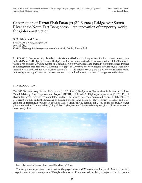
The 392.00 meter long <strong>Hazrat</strong> <strong>Shah</strong> paran (r) (2 nd Surma) Bridge over Surma river is located on Sylhet-<br />
Tamabil-Jaflong Road Improvement Project (STJRIP) <strong>of</strong> Roads & Highways department (RHD). Fig. 1<br />
shows the photograph <strong>of</strong> the completed bridge. The project has been completed during 01July 2003 to<br />
31December 2005, under the financing <strong>of</strong> Kuwait Fund for Arab Economic Development (KFAED) and Government<br />
<strong>of</strong> <strong>Bangladesh</strong> (GOB). It contains total 9 spans having lengths for 2 end spans @ 43.125 meter<br />
(abutment backwall to centerline (C/L) <strong>of</strong> the 1 st pier, and the 7 intermediate spans @ 43.55 meter center to<br />
center (c/c) piers.<br />
Fig. 1 Photograph <strong>of</strong> the completed <strong>Hazrat</strong> <strong>Shah</strong> <strong>Paran</strong> (r) Bridge<br />
The design and supervision consultants <strong>of</strong> the project were SARM Associates Ltd., et al Monico Limited,<br />
a reputed construction company <strong>of</strong> <strong>Bangladesh</strong> was the Contractor <strong>of</strong> the bridge project. The temporary<br />
251
works for the bridge were designed by Design Planning & Management Consultants Ltd. on behalf <strong>of</strong> Monico<br />
Ltd.<br />
The Author as the then Director <strong>of</strong> Monico Ltd./Director-In Charge <strong>of</strong> the project, narrates the innovative,<br />
site specific and cost-effective method <strong>of</strong> construction <strong>of</strong> the superstructure. In discussion and conclusion he<br />
gives the lessons learnt and what’s to be done for future bridge construction under such flashy rivers.<br />
2 BRIDGE DATA<br />
The deck girder bridge spans contain 7 nos. I-Section post-tensioned Prestressed Concrete (PC) girders <strong>of</strong><br />
depth 2.25 meters par span. The bridge deck elevation at its mid-length along the bridge center line (C/L) <strong>of</strong><br />
the parabolic bridge deck, is maximum 22.525 mPWD, where the corresponding girder s<strong>of</strong>fit elevation over<br />
bearing is 22.449 mPWD. The longitudinal gradient <strong>of</strong> the bridge deck is 3.5% parabolic and its cross fall is<br />
2.5%.The unsupported height <strong>of</strong> Pier from the top <strong>of</strong> pile cap to bridge bearing level was 16.674 meters at<br />
mid-length <strong>of</strong> the bridge.<br />
The cast-in-place bored piles having diameters 750mm and lengths varying between 32.00 and 35.00 meters<br />
were used for Pier and Abutment foundations. The bottom <strong>of</strong> the Pier pile caps are placed at EL. 4.50 m<br />
PWD.<br />
For PC Girders, the specified compressive cylinder strength at 28 days fc’ = 35 N/mm 2 is used. Reinforcement<br />
<strong>of</strong> ASTM A615M – 88 Grade 60 deformed Bars, having minimum yield strength fy=415 N/mm 2<br />
for all members are used. The prestressing cables composed <strong>of</strong> 7 Nos. <strong>of</strong> 12.7 mm nominal diameter 7-wire<br />
high tensile strands with minimum yield strength fy = 1580 N/mm2 & ultimate tensile strength (UTS) = 1860<br />
N/mm 2 were used.<br />
3 BACKGROUND OF INNOVATION<br />
Monico Ltd. signed the agreement for the construction <strong>of</strong> this bridge and its approaches in 01 June 2003 with<br />
a targeted completion period <strong>of</strong> 30 months, i.e. the completion date was 31 December 2005. Out <strong>of</strong> this 30<br />
months duration, 12 months are non-working period, considering the 3 flood/monsoon seasons, each <strong>of</strong> 4<br />
months duration from June to August per year. This gives net working period <strong>of</strong> 18 months only, out <strong>of</strong> which<br />
a considerable period was required to construct the cast-in-place bored piles particularly for piers in flashy<br />
river.<br />
The Contractor needed to adopt fast track construction for the bridge superstructure utilizing the monsoon<br />
season also. The methodology should be safe under the flash flood and under the cyclonic condition <strong>of</strong> the<br />
Sylhet area. The innovation adopted in the construction methodology <strong>of</strong> the bridge superstructure is described<br />
below.<br />
4 RIVER HYDROLOGY AND BATHYMETRY AT BRIDGE LOCATION<br />
Surma is a large size flashy river originated in the Manipur hills <strong>of</strong> the North eastern India. Its maximum and<br />
minimum discharges vary between 1,500 and 14 m 3 /sec. The high water level (HWL) considered in design<br />
was12.00 mPWD , which corresponds to 2000 flood. During construction period the measured HFL on 11<br />
July 2004 exceeded this design HWL by about 0.44 meter. The design low water level (LWL) was 4.156<br />
mPWD, which corresponds to 09 December 2001 water level. At bridge location river bed elevation adjacent<br />
to deep water pier was 1.092 mPWD. The flash flood may exceed 1.00 – 1.50 meters in a day.<br />
5 CONSTRUCTION METHODOLOGIES OF BRIDGE DECK GIRDERS<br />
Several options were studied as follows:<br />
5.1 Conventional method <strong>of</strong> constructing deck girders<br />
For the Government <strong>of</strong> <strong>Bangladesh</strong> (GOB)-funded small and medium span river bridges, the conventional<br />
method is by erecting scaffolding in the river bed for the entire deck girders <strong>of</strong> one span, as shown in Fig. 2.<br />
The PC girders and reinforced concrete (RC) decks are then constructed cast-in-place over bearings below<br />
252
each girder end. This has a risk <strong>of</strong> prop settlement affecting the girder and deck concreting, and further, it’s<br />
time consuming and expensive also.<br />
Fig. 2<br />
Traditional method <strong>of</strong> construction <strong>of</strong> bridge girders by erecting props<br />
5.2 PC girders are concreted as non-composite members at span level<br />
The scaffoldings are erected on river bed, as shown in Fig. 1, but for one PC girder only. The girder formwork<br />
and reinforcement are placed over the scaffolding nearer to the bearing level but away from their actual<br />
locations. After it gains adequate strength, by about 7 days, these are either partially or fully prestressed.<br />
These are then lifted and shifted to their actual positions over bearings, either before or after grouting. After<br />
all the girders are placed in position, the scaffolding is removed. The deck forms are then placed over inserts<br />
in the precast girders, and then deck concreting is done. The props are then removed for use in the other<br />
spans.<br />
The non-composite girder is designed to carry its self weight and the weight <strong>of</strong> the deck concrete and some<br />
live load. The deck is shear-connected to the precast girders. The composite girder carries the live load. The<br />
prestressing losses are estimated considering the differential shrinkage along with the other losses.<br />
This option also has the risk <strong>of</strong> prop settlement and therefore isn’t preferred.<br />
5.3 Precast girders lifted and shifted by crane<br />
The girders are constructed adjacent to the span. After prestressing, these are lifted and shifted to the span locations<br />
and placed in position over the bearings. Deck concreting is done by providing supports over the PC<br />
girders through inserts.<br />
This was found inconvenient, expensive and unsafe for the subject flashy river.<br />
5.4 Launching girder method<br />
This method is generally used for medium span river bridges. In this method the precast PC girders are constructed<br />
behind the abutment. After their partial or full prestressing these are lifted and shifted by using the<br />
launching girder and placed in the adjacent span. Deck concreting is done by supporting the formwork over<br />
the PC girders through inserts as before. The rest procedure is the same as before. Span by span construction<br />
is done sequentially thereafter.<br />
For a single bridge mobilizing the launching girder was found expensive.<br />
5.5 Launching truss method<br />
The launching truss could be designed with nosing. The depth <strong>of</strong> the pair <strong>of</strong> main trusses becomes large. Besides,<br />
truss nosing is required at each end. For the high stream current <strong>of</strong> the subject flashy river (peak flow<br />
velocity > 2.0 m/sec approximately), mobilizing the launching truss arrangement under water was considered<br />
unsafe. For the single bridge <strong>of</strong> 9 spans this was found economically not viable under the contract amount.<br />
253
5.6 Innovative use <strong>of</strong> space truss for construction <strong>of</strong> non-composite PC girder<br />
5.6.1 About the system<br />
After exploring many other options, finally developed the innovative form <strong>of</strong> space truss, as shown in Fig. 3.<br />
At the 2 ends, 2pairs <strong>of</strong> triangular arches were erected. In the middle third, one pair <strong>of</strong> normal arch was suspended<br />
from the tip <strong>of</strong> the 2 triangular arches. Additional members were then provided connecting the pairs<br />
<strong>of</strong> arches including the triangular arches to form the space truss. The erection <strong>of</strong> the whole system was done<br />
by mechanical method and jointed with nuts and bolts.<br />
The pairs <strong>of</strong> the triangular arches were first erected up to about 150 mm above the HWL for all the river<br />
spans before the arrival <strong>of</strong> the monsoon floods. These were supported over the pier caps with holding down<br />
device and the control system to arrest the longitudinal and transverse movement <strong>of</strong> the truss support due to<br />
hydrodynamic and gravity loads. These trusses were anchored and fastened with the pier shafts also. The<br />
stream flow <strong>of</strong> the flash flood could pass through the truss openings without exerting unacceptable vibrations<br />
in the submerged trusses. The erection <strong>of</strong> the whole system was done by mechanical method and jointed with<br />
nuts and bolts. Fig. 4 shows the erected trusses during the monsoon season.<br />
Fig. 3<br />
Bridge girder construction by using triangular space truss support<br />
Fig. 4<br />
Photograph shows the system <strong>of</strong> erected truss supports during monsoon season<br />
254
The spacing <strong>of</strong> the pairs <strong>of</strong> parallel trusses was designed to accommodate a suitable working platform <strong>of</strong><br />
about 5.0 meter wide with adequate working space and movement <strong>of</strong> the workers. The steel I-sections and U-<br />
Channels were used to make the top platform.<br />
On completion <strong>of</strong> one span the whole truss system was dismantled, lowered on the bed <strong>of</strong> a river vessel,<br />
brought forward to the next gap and erected on the pairs <strong>of</strong> the triangular trusses fixed earlier, as shown in<br />
Fig. 5.<br />
Fig. 5<br />
Erection / dismantling system <strong>of</strong> truss modules<br />
5.6.2 Analysis <strong>of</strong> the trusses<br />
The analysis model was developed in STAAD/Pro. The design <strong>of</strong> the truss members and their depths, particularly<br />
for the middle third, were designed so that the maximum deflection doesn’t exceed 50 mm. The objective<br />
is to select the concreting sequence such that the integrity <strong>of</strong> the green concrete at plastic stage isn’t affected.<br />
The trusses were designed as modules <strong>of</strong> uniform size so that these could be transported and re-used<br />
easily. With this truss the construction could be continued during all the seasons.<br />
The system helped the contractor in faster construction <strong>of</strong> girders with almost no risk and hindrances. The<br />
system was found environment-friendly, safe and at the same time economical also.<br />
5.7 Comparison <strong>of</strong> the financial cost <strong>of</strong> the triangular truss system and propping system<br />
• The cost analysis between the conventional propping method and triangular space truss method<br />
showed that the financial expenses <strong>of</strong> truss per linear meter <strong>of</strong> girder length are 15% higher than the<br />
propping method.<br />
• As regards salvage value <strong>of</strong> the materials, it is found that almost 40% length <strong>of</strong> props/pipes isn’t salvageable.<br />
Besides, withdrawing the props from the river bed becomes practically uncertain; even if it’s<br />
done it becomes costlier than dismantling cost <strong>of</strong> the truss. In case the props aren’t withdrawn, it will<br />
create obstruction for the river navigation subsequently. Considering the above factors, the propping<br />
method is found 30% costlier than truss method.<br />
• Comparing the repeated use and time savings <strong>of</strong> the truss system vis-à-vis the propping system the cost<br />
<strong>of</strong> the truss system was found about 10% cheaper than the prop system.<br />
• Summarizing the comparative cost <strong>of</strong> the above 2 systems, propping method is financially about 25%<br />
costlier than the truss method. Besides, it contains the risk <strong>of</strong> prop settlement harming the structure.<br />
6 LESSONS LEARNT AND CONCLUSION<br />
The lessons to be learnt from the construction <strong>of</strong> the <strong>Hazrat</strong> <strong>Shah</strong> <strong>Paran</strong> ( r) Bridge over Surma river (2 nd<br />
Surma) is that the design <strong>of</strong> the temporary works for construction <strong>of</strong> the river bridges is as important as <strong>of</strong> the<br />
design <strong>of</strong> the permanent bridges.<br />
255
The innovations in temporary works require studying different options <strong>of</strong> which some may appear not<br />
logical in the foresight but might be found logical in the hind sight. So, no options should be discarded from<br />
the initial scrutiny.<br />
The environmental load effects should be considered in the realistic manner and adequate safety measures<br />
should be provided in design and detailing <strong>of</strong> the temporary works.<br />
The specialized team <strong>of</strong> design engineers well-conversant with the scaffolding and temporary works design<br />
including the design codes and available local materials and their properties are very important.<br />
ACKNOWLEDGEMENT<br />
The author expresses deep gratitude to the management <strong>of</strong> the Monico Ltd. and Design Planning & Management<br />
Consultants Ltd. for providing all the encouragement and support in preparing this article.<br />
256