Introduction to the resistivity surveying method. The resistivity of ...
Introduction to the resistivity surveying method. The resistivity of ...
Introduction to the resistivity surveying method. The resistivity of ...

You also want an ePaper? Increase the reach of your titles
YUMPU automatically turns print PDFs into web optimized ePapers that Google loves.
17<br />
electrode spacing along <strong>the</strong> survey line is more than a few metres, <strong>the</strong>re might be practical<br />
problems in finding suitable locations for <strong>the</strong> C2 and P2 electrodes <strong>to</strong> satisfy this requirement.<br />
Ano<strong>the</strong>r disadvantage <strong>of</strong> this array is that because <strong>of</strong> <strong>the</strong> large distance between <strong>the</strong> P1 and P2<br />
electrodes, it is can pick up a large amount <strong>of</strong> telluric noise which can severely degrade <strong>the</strong><br />
quality <strong>of</strong> <strong>the</strong> measurements. Thus this array is mainly used in surveys where relatively small<br />
electrode spacings (less than 10 metres) are used. It is popular in some applications such as<br />
archaeological surveys where small electrode spacings are used. It has also been used for 3-D<br />
surveys (Li and Oldenburg 1992).<br />
This array has <strong>the</strong> widest horizontal coverage and <strong>the</strong> deepest depth <strong>of</strong> investigation.<br />
However, it has <strong>the</strong> poorest resolution, which is reflected by <strong>the</strong> comparatively large spacing<br />
between <strong>the</strong> con<strong>to</strong>urs in <strong>the</strong> sensitivity function plot (Figure 11).<br />
2.5.5 Pole-dipole array<br />
<strong>The</strong> pole-dipole array also has relatively good horizontal coverage, but it has a<br />
significantly higher signal strength compared with <strong>the</strong> dipole-dipole array and it is not as<br />
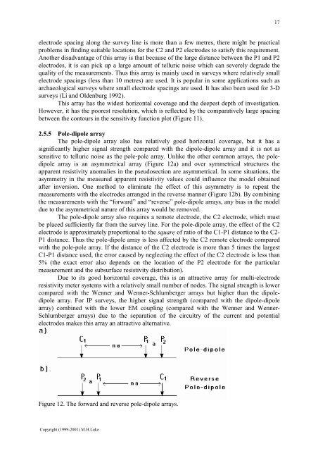
sensitive <strong>to</strong> telluric noise as <strong>the</strong> pole-pole array. Unlike <strong>the</strong> o<strong>the</strong>r common arrays, <strong>the</strong> poledipole<br />
array is an asymmetrical array (Figure 12a) and over symmetrical structures <strong>the</strong><br />
apparent <strong>resistivity</strong> anomalies in <strong>the</strong> pseudosection are asymmetrical. In some situations, <strong>the</strong><br />
asymmetry in <strong>the</strong> measured apparent <strong>resistivity</strong> values could influence <strong>the</strong> model obtained<br />
after inversion. One <strong>method</strong> <strong>to</strong> eliminate <strong>the</strong> effect <strong>of</strong> this asymmetry is <strong>to</strong> repeat <strong>the</strong><br />
measurements with <strong>the</strong> electrodes arranged in <strong>the</strong> reverse manner (Figure 12b). By combining<br />
<strong>the</strong> measurements with <strong>the</strong> “forward” and “reverse” pole-dipole arrays, any bias in <strong>the</strong> model<br />
due <strong>to</strong> <strong>the</strong> asymmetrical nature <strong>of</strong> this array would be removed.<br />
<strong>The</strong> pole-dipole array also requires a remote electrode, <strong>the</strong> C2 electrode, which must<br />
be placed sufficiently far from <strong>the</strong> survey line. For <strong>the</strong> pole-dipole array, <strong>the</strong> effect <strong>of</strong> <strong>the</strong> C2<br />
electrode is approximately proportional <strong>to</strong> <strong>the</strong> square <strong>of</strong> ratio <strong>of</strong> <strong>the</strong> C1-P1 distance <strong>to</strong> <strong>the</strong> C2-<br />
P1 distance. Thus <strong>the</strong> pole-dipole array is less affected by <strong>the</strong> C2 remote electrode compared<br />
with <strong>the</strong> pole-pole array. If <strong>the</strong> distance <strong>of</strong> <strong>the</strong> C2 electrode is more than 5 times <strong>the</strong> largest<br />
C1-P1 distance used, <strong>the</strong> error caused by neglecting <strong>the</strong> effect <strong>of</strong> <strong>the</strong> C2 electrode is less than<br />
5% (<strong>the</strong> exact error also depends on <strong>the</strong> location <strong>of</strong> <strong>the</strong> P2 electrode for <strong>the</strong> particular<br />
measurement and <strong>the</strong> subsurface <strong>resistivity</strong> distribution).<br />
Due <strong>to</strong> its good horizontal coverage, this is an attractive array for multi-electrode<br />
<strong>resistivity</strong> meter systems with a relatively small number <strong>of</strong> nodes. <strong>The</strong> signal strength is lower<br />
compared with <strong>the</strong> Wenner and Wenner-Schlumberger arrays but higher than <strong>the</strong> dipoledipole<br />
array. For IP surveys, <strong>the</strong> higher signal strength (compared with <strong>the</strong> dipole-dipole<br />
array) combined with <strong>the</strong> lower EM coupling (compared with <strong>the</strong> Wenner and Wenner-<br />
Schlumberger arrays) due <strong>to</strong> <strong>the</strong> separation <strong>of</strong> <strong>the</strong> circuitry <strong>of</strong> <strong>the</strong> current and potential<br />
electrodes makes this array an attractive alternative.<br />
Figure 12. <strong>The</strong> forward and reverse pole-dipole arrays.<br />
Copyright (1999-2001) M.H.Loke