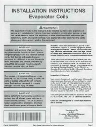
installation & operating instructions for self contained - Alpine Home ...
installation & operating instructions for self contained - Alpine Home ...
installation & operating instructions for self contained - Alpine Home ...

You also want an ePaper? Increase the reach of your titles
YUMPU automatically turns print PDFs into web optimized ePapers that Google loves.
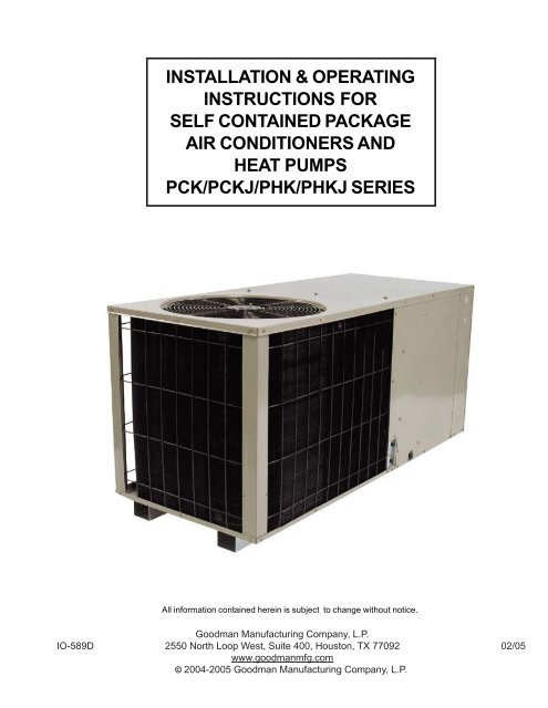
INSTALLATION & OPERATING<br />
INSTRUCTIONS FOR<br />
SELF CONTAINED PACKAGE<br />
AIR CONDITIONERS AND<br />
HEAT PUMPS<br />
PCK/PCKJ/PHK/PHKJ SERIES<br />
All in<strong>for</strong>mation <strong>contained</strong> herein is subject to change without notice.<br />
Goodman Manufacturing Company, L.P.<br />
IO-589D 2550 North Loop West, Suite 400, Houston, TX 77092 02/05<br />
www.goodmanmfg.com<br />
© 2004-2005 Goodman Manufacturing Company, L.P.
INDEX<br />
INTRODUCTION........................................................... 2<br />
Checking Product Received ......................................... 2<br />
Message to <strong>Home</strong>owner ............................................... 2<br />
Be<strong>for</strong>e Beginning Installation ........................................ 2<br />
REPLACEMENT PARTS .............................................. 2<br />
Ordering Parts ............................................................... 2<br />
Service Parts Department ............................................. 2<br />
SAFETY INSTRUCTIONS ............................................ 3<br />
Recognize Safety Symbols, Labels and Warning ......... 3<br />
CODES AND REGULATIONS ...................................... 3<br />
General ......................................................................... 3<br />
EPA Regulations ........................................................... 3<br />
National Codes ............................................................. 3<br />
MAJOR COMOPONENTS............................................ 3<br />
General ......................................................................... 3<br />
INSTALLATION ............................................................ 3<br />
Pre-Installation Checkpoints ......................................... 3<br />
Clearance ...................................................................... 3<br />
Location ........................................................................ 4<br />
Outside Slab Installation ............................................... 4<br />
Rooftop Installation ....................................................... 4<br />
DUCTING ...................................................................... 4<br />
Connecting the Return and Supply Flexible Duct ......... 4<br />
Plenum Application ....................................................... 5<br />
Filters ............................................................................ 5<br />
PIPING .......................................................................... 5<br />
Condensate Drain ......................................................... 5<br />
WIRING ......................................................................... 5<br />
High Voltage Wiring ...................................................... 6<br />
Low Voltage Wiring ....................................................... 6<br />
Internal Wiring ............................................................... 6<br />
OPERATION ................................................................. 6<br />
Start-Up Procedure and Checklist ................................ 6<br />
Heat Pump Start-Up Procedure .................................... 6<br />
Final System Checks .................................................... 6<br />
COMPONENTS ............................................................ 7<br />
Contactor ...................................................................... 7<br />
Crankcase Heater ......................................................... 7<br />
Condenser Motor .......................................................... 7<br />
Compressor .................................................................. 7<br />
Contactor Relay ............................................................ 7<br />
Defrost Control .............................................................. 7<br />
Outdoor Thermostat ...................................................... 7<br />
Reversing Valve Coil ..................................................... 7<br />
EXPLANATION AND GUIDANCE ................................ 7<br />
Heat Pump .................................................................... 7<br />
HEAT PUMP REFRIGERANT CIRCUIT ....................... 8<br />
Cooling and Heating Circuit .......................................... 8<br />
DEFROST CONTROL .................................................. 9<br />
Operation ...................................................................... 9<br />
AIR FLOW MEASUREMENT AND ADJUSTMENT ..... 9<br />
CHECKING CHARGE .................................................. 9<br />
Suction Pressure Temperature ..................................... 9<br />
Operating Pressures ................................................... 10<br />
System Superheat ...................................................... 10<br />
MAINTENANCE.......................................................... 10<br />
Service ........................................................................ 10<br />
Inadequate Air Volume Through Indoor Coil ............... 10<br />
Outside Air into Return Duct ....................................... 10<br />
Undercharge ............................................................... 10<br />
Poor “Terminating” Sensor Contact ............................ 10<br />
Malfunctioning Reversing Valve .................................. 10<br />
TROUBLESHOOTING CHART .................................. 11<br />
INTRODUCTION<br />
Checking Product Received<br />
Upon receiving the unit, inspect it <strong>for</strong> damage from shipment.<br />
Claims <strong>for</strong> damage, either shipping or concealed, should be<br />
filed immediately with the shipping company. Check the unit<br />
model number, specifications, electrical characteristics and<br />
accessories to determine if they are correct. In the event an<br />
incorrect unit is shipped, it must be returned to the supplier<br />
and must NOT be installed. The manufacturer assumes no<br />
responsibility <strong>for</strong> <strong>installation</strong> of incorrectly shipped units.<br />
Message to the <strong>Home</strong>owner<br />
These <strong>instructions</strong> are addressed primarily to the installer;<br />
however, useful maintenance in<strong>for</strong>mation is included and<br />
should be kept, after <strong>installation</strong>, <strong>for</strong> future reference.<br />
Be<strong>for</strong>e Beginning Installation<br />
Carefully read all <strong>instructions</strong> <strong>for</strong> the <strong>installation</strong> prior to<br />
installing unit. Make sure each step or procedure is understood<br />
and any special considerations are taken into account be<strong>for</strong>e<br />
starting <strong>installation</strong>. Assemble all tools, hardware and supplies<br />
needed to complete the <strong>installation</strong>. Some items may need<br />
to be purchased locally. After deciding where to install unit,<br />
closely look the location over - both the inside and outside of<br />
home. Note any potential obstacles or problems that might<br />
be encountered as noted in this manual. Choose a more<br />
suitable location if necessary.<br />
REPLACEMENT PARTS<br />
Ordering Parts<br />
When reporting shortages or damages, or ordering repair<br />
parts, give the complete unit model and serial numbers as<br />
stamped on the unit’s nameplate. Replacement parts <strong>for</strong> this<br />
appliance are available through your contractor or local<br />
distributor. For the location of your nearest distributor, consult<br />
the white business pages, the yellow page section of the local<br />
telephone book or contact:<br />
SERVICE PARTS DEPARTMENT<br />
GOODMAN MANUFACTURING COMPANY, L.P.<br />
2550 NORTH LOOP WEST, SUITE 400<br />
HOUSTON, TEXAS 77092<br />
(713) 861 – 2500<br />
IMPORTANT SAFETY INSTRUCTIONS<br />
Recognize Safety Symbols, Words, and Labels<br />
The following symbols and labels are used throughout this<br />
manual to indicate immediate or potential hazards. It is the<br />
IO-589D 2<br />
02/05
owner’s responsibility to read and comply with all safety<br />
in<strong>for</strong>mation and <strong>instructions</strong> accompanying these symbols.<br />
Failure to heed safety in<strong>for</strong>mation increases the risk of serious<br />
personal injury or death, property damage and/or product<br />
damage.<br />
DANGER<br />
IMMEDIATE HAZARDS WHICH WILL RESULT IN<br />
PROPERTY DAMAGE, PRODUCT DAMAGE, SEVERE<br />
PERSONAL INJURY OR DEATH.<br />
WARNING<br />
HAZARDS OR UNSAFE PRACTICES COULD RESULT IN<br />
PROPERTY DAMAGE, PRODUCT DAMAGE, SEVERE<br />
PERSONAL INJURY OR DEATH.<br />
CAUTION<br />
HAZARDS OR UNSAFE PRACTICES WHICH MAY RESULT<br />
IN PROPERTY DAMAGE, PRODUCT DAMAGE,<br />
PERSONAL INJURY OR DEATH.<br />
WARNING<br />
DO NOT CONNECT TO OR USE IN CONJUNCTION WITH<br />
THIS UNIT ANY DEVICES FOR THE PURPOSE OF SAVING<br />
ENERGY OR INCREASING OPERATING EFFICIENCIES<br />
THAT ARE NOT DESIGN CERTIFIED FOR USE WITH THIS<br />
UNIT OR HAVE NOT BEEN TESTED AND APPROVED BY<br />
GOODMAN. SERIOUS PROPERTY OR PERSONAL<br />
DAMAGE, REDUCED UNIT PERFORMANCE AND/OR<br />
HAZARDOUS CONDITIONS MAY RESULT FROM THE USE<br />
OF DEVICES THAT HAVE NOT BEEN APPROVED OR<br />
CERTIFIED BY GOODMAN.<br />
WARNING<br />
DO NOT STORE COMBUSTIBLE MATERIALS OR USE<br />
GASOLINE OR OTHER FLAMMABLE LIQUIDS OR<br />
VAPORS IN THE VICINITY OF THIS APPLIANCE SO AS<br />
TO PREVENT THE RISK OF PROPERTY DAMAGE OR<br />
PERSONAL INJURY. HAVE YOUR CONTRACTOR POINT<br />
OUT AND IDENTIFY THE VARIOUS CUT-OFF DEVICES,<br />
SWITCHES, ETC. THAT SERVES YOUR COMFORT<br />
EQUIPMENT.<br />
WARNING<br />
DO NOT, UNDER ANY CIRCUMSTANCES, CONNECT<br />
DUCT WORK TO ANY OTHER HEAT PRODUCING DEVICE<br />
SUCH AS FIREPLACE INSERT, STOVE, ETC.<br />
UNAUTHORIZED USE OF SUCH DEVICES MAY RESULT<br />
IN PROPERTY DAMAGE, FIRE, CARBON MONOXIDE<br />
POISONING, EXPLOSION, PERSONAL INJURY OR<br />
DEATH.<br />
CODES AND REGULATIONS<br />
General<br />
The PCK & PHK series air conditioners and heat pumps are<br />
designed <strong>for</strong> OUTDOOR USE ONLY. This series is available<br />
in cooling Capacities of 2, 2 ½, 3, 3 ½, 4 and 5 nominal tons<br />
of cooling. Optional field installed heat kits are available in<br />
5,8,10,15 and 20 KW. The units can be easily installed in<br />
manufactured or modular homes with existing high-static duct<br />
work. The units can also be easily converted to accommodate<br />
a plenum <strong>for</strong> normal or low-static applications. The PCK &<br />
PHK series are <strong>self</strong> <strong>contained</strong> packaged units so the only<br />
connections needed <strong>for</strong> <strong>installation</strong> are the supply and return<br />
ducts, the line and low voltage wiring and drain connection.<br />
The units are ETL listed and ARI certified.<br />
The in<strong>for</strong>mation on the rating plate is in compliance with the<br />
FTC & DOE rating <strong>for</strong> single phase units. The three phase<br />
units in this series are not covered under the DOE certified<br />
program. The efficiency ratings of these units are a product of<br />
thermal efficiency determined under continuos <strong>operating</strong><br />
conditions independent of any installed system.<br />
IMPORTANT: THE UNITED STATES ENVIRONMENTAL<br />
PROTECTION AGENCY (EPA) HAS ISSUED VARIOUS<br />
REGULATIONS REGARDING THE INTRODUCTION AND<br />
DISPOSAL OF REFRIGERANTS IN THIS UNIT. FAILURE TO<br />
FOLLOW THESE REGULATIONS MAY HARM THE<br />
ENVIRONMENT AND CAN LEAD TO THE IMPOSITION OF<br />
SUBSTANTIAL FINES. BECAUSE REGULATIONS MAY VARY<br />
DUE TO PASSAGE OF NEW LAWS, WE SUGGEST A<br />
CERTIFIED TECHNICIAN PERFORM ANY WORK DONE ON<br />
THIS UNIT. SHOULD YOU HAVE ANY QUESTIONS PLEASE<br />
CONTACT THE LOCAL OFFICE OF THE EPA.<br />
National Codes<br />
This product is designed and manufactured to permit<br />
<strong>installation</strong> in accordance with National Codes. It is the installer’s<br />
responsibility to install the product in accordance with National<br />
Codes and/or prevailing local codes and regulations.<br />
MAJOR COMPONENTS<br />
The unit includes a hermetically sealed refrigerating system<br />
(consisting of a compressor, condenser coil, evaporator coil<br />
with capillary tube assembly), an indoor blower, a condenser<br />
fan and all necessary internal electrical wiring. The heat pump<br />
also includes a reversing valve, solenoid, defrost thermostat<br />
and control. The system is factory-evacuated, charged and<br />
per<strong>for</strong>mance tested. Refrigerant amount and type are indicated<br />
on rating plate. (See Operation-General)<br />
INSTALLATION<br />
This product is designed and manufactured to permit <strong>installation</strong><br />
in accordance with National Codes. It is the installer’s<br />
responsibility to install the product in accordance with National<br />
Codes and/or prevailing local codes and regulations.<br />
Pre-Installation Checkpoints<br />
Be<strong>for</strong>e attempting any <strong>installation</strong>, the following points should<br />
be considered:<br />
• Structural strength of supporting members<br />
• Clearances and provision <strong>for</strong> servicing<br />
• Power supply and wiring<br />
• Air duct connections<br />
• Drain facilities and connections<br />
• Location may be on any four sides of a home,<br />
manufactured or modular, to minimize noise<br />
Clearance<br />
The outdoor heat pump unit is designed to be located outside<br />
the building with unobstructed condenser air inlet and discharge.<br />
Additionally, the unit must be situated to permit access <strong>for</strong><br />
service and <strong>installation</strong>. Condenser air enters from three sides.<br />
Air discharges upward from the top of the unit. Refrigerant<br />
tube electrical connections are made on the right side of the<br />
unit as you face the compressor compartment. The best and<br />
most common application is <strong>for</strong> the unit to be located 10” from<br />
IO-589D 3<br />
02/05
ack wall with the connection side facing the wall. This “close<br />
to the wall” application minimizes exposed tubing and wiring<br />
and reduces the space <strong>for</strong> children to run around the unit which<br />
may cause damage to the tubes or wiring.<br />
Close to the wall application assures free, unobstructed air to<br />
the other two sides. In more confined application spaces,<br />
such as corners provide a minimum 10” clearance on all air<br />
inlet sides. Allow 18” minimum <strong>for</strong> service access to the<br />
compressor compartment and controls. The top of the unit<br />
should be completely unobstructed. If units are to be located<br />
under an overhang, there should be a minimum of 36”<br />
clearance and provisions made to deflect the warm discharge<br />
air out from the overhang.<br />
Location<br />
Consider the affect of outdoor fan noise on conditioned space<br />
and any adjacent occupied space. It is recommended that<br />
the unit be placed so that discharge does not blow toward<br />
windows less than 25 feet away.<br />
The outdoor unit should be set on a solid, level foundation -<br />
preferably a concrete slab at least 4 inches thick. The slab<br />
should be above ground level and surrounded by a graveled<br />
area <strong>for</strong> good drainage. Any slab used as a unit’s foundation<br />
should not adjoin the building as it is possible that sound and<br />
vibration may be transmitted to the structure. For rooftop<br />
<strong>installation</strong>, steel or treated wood beams should be used as<br />
unit support <strong>for</strong> load distribution.<br />
Heat pumps require special location consideration in areas of<br />
heavy snow accumulation and/or areas with prolonged<br />
continuous subfreezing temperatures. Heat pump unit bases<br />
are cutout under the outdoor coil to permit drainage of frost<br />
accumulation. The unit must be situated to permit free<br />
unobstructed drainage of the defrost water and ice. A minimum<br />
3" clearance under the outdoor coil is required in the milder<br />
climates.<br />
Outside Slab Installation<br />
1. The unit must be mounted on a solid, level foundation that<br />
does not adjoin to the building, as it is possible that the<br />
sound and the vibration may be transmitted to the structure.<br />
2. Select a location that will minimize the length of the supply<br />
and return ducts.<br />
3. Select a location where external water drainage cannot collect<br />
around the unit.<br />
4. Consideration should also be given to shade, appearance<br />
and noise.<br />
Rooftop Installation<br />
FIGURE 1<br />
1. Be<strong>for</strong>e locating the unit on the roof, make sure that the<br />
strength of the roof and beams is adequate at that point to<br />
support the weight involved. (See specification sheet <strong>for</strong><br />
weight of units.) This is very important and the installer’s<br />
responsibility.<br />
2. Make proper consideration <strong>for</strong> the weather–tight integrity<br />
of the roof and proper drainage of condensate.<br />
3. Consideration should also be given to shade, appearance<br />
and noise.<br />
DUCTING<br />
WARNING<br />
FIGURE 2<br />
DO NOT UNDER ANY CIRCUMSTANCES CONNECT<br />
RETURN DUCTWORK TO ANY OTHER HEAT<br />
PRODUCING DEVICES SUCH AS FIREPLACE INSERT,<br />
STOVE, ETC. UNAUTHORIZED USE OF SUCH DEVICES<br />
MAY RESULT IN PROPERTY DAMAGE, FIRE, CARBON<br />
MONOXIDE POISONING, EXPLOSION, PERSONAL<br />
INJURY OR DEATH.<br />
Ducting work should be fabricated by the installing contractor<br />
in accordance with local codes. Industry manuals may be<br />
used as a guide when sizing and designing the duct systemsuch<br />
as NESCA (National Environmental Systems<br />
Contractors Association, 1501 Wilson Blvd., Arlington, Virginia<br />
22209).<br />
The unit should be placed as close to the space to be airconditioned<br />
as possible allowing clearance dimensions as<br />
indicated. Ducts should run as directly as possible to supply<br />
and return outlets. Use of non-flammable weatherproof<br />
flexible connectors on both supply and return connections at<br />
the unit to reduce noise transmission is recommended.<br />
It is preferable to install the unit on the roof of the structure if<br />
the registers or diffusers are located in the wall or ceiling. A<br />
slab <strong>installation</strong> is recommended when the registers are low<br />
on the wall or in the floor.<br />
Connecting the Return and Supply Flexible Duct in<br />
Manufactured or Modular Housing Application<br />
The return and supply fittings are to be attached at the unit to<br />
a suitable square to round duct converter. Your distributor<br />
has a factory designed square to round converter transition.<br />
The model #’s of these kits are as follows: Small Chassis<br />
SQRPCH-1, Medium Chassis SQRPCH-2, Large Chassis<br />
SQRPCH-3 (See Specification Sheets <strong>for</strong> Dimension details).<br />
The SQRPCH-1 has 12" duct collar on supply and 14" duct<br />
collar (equivalent diameter, opening is oval) on the return.<br />
The SQRPCH-2 has 14" duct collar on supply and 16" duct<br />
collar (equivalent diameter, opening is oval) on the return.<br />
The SQRPCH-3 has 14" duct collar on supply and 18" duct<br />
IO-589D 4<br />
02/05
collar (equivalent diameter, opening is oval) on the return.<br />
The collars are to be slipped into the openings, and the flanges<br />
bent around the converter. The square to round converter is<br />
attached to the flanges of the square duct openings. The<br />
flexible duct is then clamped on to the collars. Once the duct<br />
is affixed to the unit, seal the collars and flanges with a<br />
proper waterproof sealant (See Figure 3).<br />
It is strongly encouraged to use appropriately sized ducts<br />
based upon the CFM <strong>for</strong> your application (unit’s CFM). If<br />
duct sizing through industry manuals or air duct calculators<br />
require larger ducts than converter openings, run larger duct<br />
size up to unit converter openings and reduce with a reducer<br />
duct fitting or transition right at the unit.<br />
MINIMUM FILTER SIZE<br />
NOMINAL SIZE (INCHES) NOMINAL AREA (SQ. FT.)<br />
10x20 1.4<br />
14x20 1.9<br />
14x25 2.4<br />
15x20 2.1<br />
16x20 2.2<br />
16x25 2.8<br />
20x20 2.8<br />
20x25 3.5<br />
25x25 4.3<br />
Balancing dampers are recommended <strong>for</strong> each branch duct<br />
in the supply system. Ductwork should be properly supported<br />
from the unit.<br />
NOTE: Proper sealing of all duct work and air handling<br />
compartments is extremely important to overall unit efficiency.<br />
FILTERS<br />
Filters are not provided with unit, and must be supplied and<br />
installed in the return duct system by the installer. A field<br />
installed filter grille is recommended <strong>for</strong> easy and convenient<br />
access to the filters <strong>for</strong> periodic inspection and cleaning. Filters<br />
must have adequate face area <strong>for</strong> the rated quantity of the<br />
unit. See air delivery tables (Figure 4) <strong>for</strong> recommended filter<br />
size.<br />
PIPING<br />
Condensate Drain<br />
The condensate drain connection of the evaporator is a half<br />
coupling of ¾” N.P.T. A trap must be provided to have Proper<br />
condensate drainage.<br />
OUTER FLANGE<br />
STARTER FLANGE<br />
Nominal Filter Area<br />
Square Feet<br />
TABLE 1<br />
FIGURE 3<br />
SQUARE TO ROUND<br />
DUCT CONVERTER PANEL<br />
BEAD<br />
7<br />
6<br />
5<br />
4<br />
3<br />
2<br />
500 1000 1500 2000 2500 3000 3500<br />
DISPOSABLE FILTER<br />
PERMANENT FILTER<br />
Airflow - SCFM<br />
FIGURE 4<br />
FIGURE 5<br />
Install condensate drain trap as shown. Use ¾ “ drain<br />
connection size or larger. Do not operate without trap. Unit<br />
must be level or slightly inclined toward drain.<br />
WIRING<br />
All wiring should be made in accordance with the National<br />
Electrical Code. The local Power Company should be<br />
consulted to determine the availability of sufficient power to<br />
operate the unit. The voltage, frequency, and phase at the<br />
power supply should be checked to make sure it corresponds<br />
to the unit’s RATED VOLTAGE REQUIREMENT.<br />
Install a branch circuit fused disconnect near the unit, in<br />
accordance with the N.E.C. or local codes. Wire sizes and<br />
overcurrent protection should be determined from the unit<br />
nameplate ampacity and in accordance with Table 4 (page 6)<br />
or the N.E.C. Under no circumstances should wiring be sized<br />
smaller that is recommended by either of these two sources.<br />
Fuses smaller than that recommended on the wiring diagrams<br />
could result in unnecessary fuse failure or service calls. The<br />
use of protective devices of larger size than indicated could<br />
result in extensive damage to the equipment. The manufacturer<br />
bears no responsibility <strong>for</strong> damage caused to equipment as<br />
result of the use of larger than is recommended size protective<br />
devices.<br />
All units have undergone a run test prior to packaging <strong>for</strong><br />
shipment. This equipment has been started at minimum rated<br />
voltage and checked <strong>for</strong> satisfactory operation. Do not attempt<br />
to operate this unit if the voltage is not within the minimum<br />
and maximum voltages shown on nameplate.<br />
All exterior wiring must be within approved weatherproof<br />
conduit. The unit must be permanently grounded in<br />
accordance with local codes, or in absence of local codes,<br />
with N.E.C ANSI/ NFPA NO. 70-1984 or latest edition by using<br />
PLENUM APPLICATION<br />
A suitable plenum or square duct must be constructed. The<br />
duct cross-sectional area should be determined by industry<br />
duct sizing manuals or air duct calculators.<br />
On ductwork exposed to outside air conditions of temperature<br />
and humidity, use an insulation with a good K factor, and a<br />
vapor barrier. Industry practices should be followed.<br />
IO-589D 5<br />
ground lug in the control box.<br />
02/05
Fuses or HACR type circuit breakers may be used where<br />
codes permit.<br />
with the appliance must be replaced, the wire gauge and<br />
insulation must be the same as the original wiring.<br />
Trans<strong>for</strong>mer is wired <strong>for</strong> 230 volts on the 208/230 models.<br />
See wiring diagram <strong>for</strong> 208 volt wiring.<br />
BRANCH CIRCUIT AMPACITY 15 20 25 30 35 40 45 50<br />
SUPPLY WIRE LENGTH -<br />
FEET<br />
200 6 4 4 4 3 3 2 2<br />
150 8 6 6 4 4 4 3 3<br />
100 10 8 8 6 6 6 4 4<br />
50 14 12 10 10 8 8 6 6<br />
FIGURE 6<br />
Note: Some single phase units are equipped with a single<br />
pole contactor. Caution must be exercised when servicing as<br />
only one leg of the power supply is broken with the contractor.<br />
To wire the unit, make the following high and low voltage<br />
connections.<br />
High Voltage Wiring: (See Figure 6)<br />
a. Single Phase- Two leads should be connected to terminals<br />
L1 & L2 in the electrical control section, using wire sizes<br />
specified in wiring table.<br />
b. Three Phase- Three leads should be connected to terminals<br />
L1, L2 and L3 in the electrical section, using wire sizes<br />
specified in wiring table.<br />
Low Voltage Wiring: (See Figure 6)<br />
a. Air Conditioners- Connect 24V wires from the thermostat<br />
to the corresponding wires in the control box using No.<br />
18AWG as follows:<br />
LEAD<br />
Red<br />
Green<br />
Yellow<br />
Brown<br />
White<br />
THERMOSTAT<br />
R (24V)<br />
G (Fan)<br />
Y (Cool)<br />
W1 (Heat)*<br />
W2 (Heat)*<br />
TABLE 2<br />
b. Heat Pumps- Connect 24V wires from the thermostat to<br />
the corresponding wires in the control box using No. 18AWG<br />
as follows:<br />
TERMINAL THERMOSTAT<br />
Red<br />
R (24V)<br />
Green<br />
G (Fan)<br />
Orange O (Rev. Valve)<br />
Brown W1 (Heat, 2nd)*<br />
White W2 (Heat 3rd)*<br />
Yellow<br />
Y (Cool)<br />
C (Blue) C (Common)<br />
*Optional field installed heat connections<br />
TABLE 3<br />
Internal Wiring:<br />
A diagram detailing the internal wiring of this unit is located on<br />
the electrical box cover. If any of the original wire supplied<br />
TABLE 4<br />
1. For branch circuit wiring (main power supply to unit<br />
disconnect), the minimum wire size <strong>for</strong> the length of the<br />
run can be determined from Table 4 using the circuit<br />
ampacity, found on the unit rating plate. From the unit<br />
disconnect to unit, the smallest wire size allowable in Table<br />
4 may be used <strong>for</strong> the ampacity, as the Disconnect must<br />
be in sight of the unit.<br />
2. Wire size based on 60° C rated wire insulation and 30° C<br />
Ambient Temperature (86° F).<br />
3. For more than 3 conductors in a raceway or cable, see the<br />
N.E.C. <strong>for</strong> derating the ampacity of each conductor.<br />
OPERATION<br />
Start-Up Procedure and Checklist<br />
Begin with power turned off at all disconnects.<br />
1. Turn thermostat system switch to “Cool,” fan switch to<br />
“Auto” and turn temperature setting as high as it will go.<br />
Remove thermostat cover to allow observation of mercury<br />
bulb.<br />
2. Inspect all registers and set them to the normal open<br />
position.<br />
3. Turn on the electrical supply at the disconnect.<br />
4. Turn the fan switch to the “ON” position. The blower should<br />
operate.<br />
5. Turn the fan switch to “Auto” position. The blower should<br />
stop.<br />
6. Slowly lower the cooling temperature until the mercury bulb<br />
makes contact. The compressor, blower and fan should<br />
now be <strong>operating</strong>. Allow the unit to run 10 minutes, make<br />
sure cool air is being supplied by the unit.<br />
7. Turn the temperature setting to the highest position,<br />
stopping the unit.<br />
8. Turn the thermostat system switch to “OFF” and disconnect<br />
all power when servicing the unit.<br />
Heat Pump Start-Up Procedure<br />
9. Check the cooling mode <strong>for</strong> the heat pump in the same<br />
manner as above. The reversing valve is energized when<br />
the thermostat is placed in the cooling position. A clicking<br />
sound should be noticeable from the reversing valve. By<br />
lowering the temperature setting to call <strong>for</strong> cooling, the<br />
contractor is energized. The compressor, blower and fan<br />
should then be running. After the cooling mode is checked<br />
out, turn the thermostat system switch to “OFF”.<br />
10. Turn the thermostat system switch to “HEAT” and fan switch<br />
to “AUTO”.<br />
IO-589D 6<br />
02/05
11. Slowly raise the heating temperature setting. When the<br />
heating first stage mercury bulb (upper) makes contact,<br />
stop moving the lever. The compressor, blower and fan<br />
should now be running with the reversing valve in the deenergized<br />
(heating) position. After giving the unit time to<br />
settle out, make sure the unit is supplying heated air.<br />
12. If the out door ambient is above 80°F, the unit may trip on<br />
its high pressure cut out when on heating. The compressor<br />
should stop. The heating cycle must be thoroughly<br />
checked, so postpone the test to another day when<br />
conditions are more suitable but-DO NOT FAIL TO TEST.<br />
If the out door ambient is low and the unit operates properly<br />
on the heating cycle, you may check the pressure cutout<br />
operation by blocking off the indoor return air until the unit<br />
trips.<br />
13. If unit operates properly in the heating cycle, raise the<br />
temperature setting until the heating second stage mercury<br />
bulb makes contact. Supplemental resistance heat, if<br />
installed should now come on. Make sure it<br />
operates properly.<br />
NOTE: If outdoor thermostats are installed the outdoor<br />
ambient must be below the set point of these<br />
thermostats <strong>for</strong> the heaters to operate. It may be<br />
necessary to jumpers these thermostats to check<br />
heater operation if outdoor ambient is mild.<br />
14. For thermostats with emergency heat switch, return to step<br />
11. The emergency heat switch is located at the bottom of<br />
the thermostat. Move the switch to emergency heat. The<br />
heat pump will stop, the blower will continue to run, all<br />
heaters will come on and the thermostat emergency heat<br />
light will come on.<br />
15. If checking the unit in the wintertime, when the outdoor<br />
coil is cold enough to actuate the defrost control, observe<br />
at least one defrost cycle to make sure the unit defrosts<br />
completely.<br />
Final System Checks<br />
16. Check to see if all supply and return air grilles are adjusted<br />
and the air distribution system is balanced <strong>for</strong> the best<br />
compromise between heating and cooling.<br />
17. Check <strong>for</strong> air leaks in the ductwork.<br />
18. See Sections on Air Flow Measurement and Adjustment<br />
and Checking Charge.<br />
19. Make sure the unit is free of “rattles”, and the tubing in the<br />
unit is free from excessive vibration. Also make sure tubes<br />
or lines are not rubbing against each other or sheet metal<br />
surfaces or edges. If so, correct the trouble.<br />
20. Set the thermostat at the appropriate setting <strong>for</strong> cooling<br />
and heating or automatic changeover <strong>for</strong> normal use.<br />
21. Be sure the Owner is instructed on the unit operation, filter,<br />
servicing, correct thermostat operation, etc.<br />
The <strong>for</strong>egoing “Start-up Procedure and Check List” is<br />
recommended to serve as an indication that the unit will<br />
operate normally.<br />
COMPONENTS<br />
1. Contactor - This control is activated (closed) by the room<br />
thermostat <strong>for</strong> both heating and cooling. The contactor has<br />
a 24V coil and supplies power to the compressor and<br />
outdoor fan motor.<br />
compressor damage. The insert type heater is <strong>self</strong> regulating.<br />
It is connected electrically to the contactor L1 and L2<br />
terminals.<br />
3. Condenser motor - This item is activated by the contactor<br />
during heating and cooling, except during defrost and<br />
emergency heat operation.<br />
4. Compressor - This item is activated by the contactor <strong>for</strong><br />
heating and cooling, except during emergency heat. It is<br />
protected by an internal overload.<br />
5. Contactor Relay - This control is activated by the<br />
thermostat (24V coil) and supplies power to the contactor.<br />
6. Defrost Control - The Defrost control provides time/<br />
temperature initiation and termination of the defrost cycle.<br />
When a Defrost cycle is initiated, the defrost control shifts<br />
the reversing valve to “cooling” mode, stops the outdoor<br />
fan and brings on supplemental heat. Normally, a Defrost<br />
cycle will take only 2-3 minutes unless system is low on<br />
charge or outdoor conditions are severe. (Windy and cold)<br />
7. Outdoor Thermostat - These optional controls are used<br />
to prevent full electric heater operation at varying outdoor<br />
ambient (0° F-to 45° F). They are normally open above<br />
their set points and closed below to permit staging of indoor<br />
supplement heater operation. If the outdoor ambient<br />
temperature is below 0° F (-18° C) with 50% or higher RH,<br />
an outdoor thermostat (OT) must be installed and set at<br />
(0°) on the dial. Failure to comply wth this requirement<br />
may result in damage to the product which may not be<br />
covered by the manufacturer’s warranty.<br />
8. Reversing Valve Coil - This coil is activated by the<br />
thermostat, in the cooling mode and during defrost. It<br />
positions the reversing valve pilot valve <strong>for</strong> cooling<br />
operation.<br />
EXPLANATION AND GUIDANCE (HEAT PUMP)<br />
The heat pump is a relatively simple device. It operates exactly<br />
as a Summer Air Conditioner unit when it is on the cooling<br />
cycle. There<strong>for</strong>e, all the charts and data <strong>for</strong> service that apply<br />
to summer air conditioning apply to the heat pump when it is<br />
on the cooling cycle, and most apply on the heating cycle<br />
except that “condenser” becomes “evaporator”, “evaporator”<br />
becomes “condenser”, “cooling” becomes “heating”.<br />
When the heat pump is on the heating cycle, it is necessary to<br />
redirect the refrigerant flow through the refrigerant circuit<br />
external to the compressor. This is accomplished with a<br />
reversing valve. Thus, the hot discharge vapor from the<br />
compressor is directed to the indoor coil (evaporator on the<br />
cooling cycle) where the heat is removed, and the vapor<br />
condenses to liquid. It then goes through the expansion device<br />
to the outdoor coil (condenser on the cooling cycle) where the<br />
liquid is evaporated, and the vapor goes to the compressor.<br />
When the solenoid valve coil is operated either from heating<br />
to cooling or vice versa, the piston in the reversing valve to the<br />
low pressure (high pressure) reverse positions in the reversing<br />
valve.<br />
The following figures show a schematic of a heat pump on the<br />
cooling cycle and the heating cycle. In addition to a reversing<br />
valve, a heat pump is equipped with an expansion device and<br />
check valve <strong>for</strong> the indoor coil, and similar equipment <strong>for</strong> the<br />
outdoor coil. It is also provided with a defrost control system.<br />
The expansion devices are flowrator distributors and per<strong>for</strong>m<br />
the same function on the heating cycle as on the cooling cycle.<br />
The flowrator distributors also act as check valves to allow<br />
2. Crankcase Heater – This item is “ON” whenever power is<br />
supplied to the unit. It warms the compressor crankcase<br />
thereby preventing liquid migration and subsequent<br />
IO-589D 7<br />
02/05
<strong>for</strong> the reverse of refrigerant flow.<br />
When the heat pump is on the heating cycle, the outdoor coil<br />
is functioning as an evaporator. The temperature of the<br />
refrigerant in the outdoor coil must be below the temperature<br />
of the outdoor air in order to extract heat from the air. Thus,<br />
the greater the difference in the outdoor temperature and the<br />
outdoor coil temperature, the greater the heating capacity of<br />
the heat pump. This phenomenon is a characteristic of a heat<br />
pump. It is a good practice to provide supplementary heat <strong>for</strong><br />
all heat pump <strong>installation</strong>s in areas where the temperature<br />
drops below 45° F. It is also a good practice to provide<br />
sufficient supplementary heat to handle the entire heating<br />
requirement should there be a component failure of the heat<br />
pump, such as a compressor, or refrigerant leak, etc.<br />
Since the temperature of the liquid refrigerant in the outdoor<br />
COOLING<br />
HEAT PUMP REFRIGERANT CIRCUIT<br />
SERVICE VALVE<br />
SERVICE PORT<br />
coil on the heating cycle is generally below freezing point,<br />
frost <strong>for</strong>ms on the surfaces of the outdoor coil under certain<br />
weather conditions of temperature and relative humidity.<br />
There<strong>for</strong>e, it is necessary to reverse the flow of the refrigerant<br />
to provide hot gas in the outdoor coil to melt the frost<br />
accumulation. This is accomplished by reversing the heat<br />
pump to the cooling cycle. At the same time, the outdoor fan<br />
stops to hasten the temperature rise of the outdoor coil and<br />
lessen the time required <strong>for</strong> defrosting. The indoor blower<br />
continues to run and the supplementary heaters are energized.<br />
DEFROST CONTROL<br />
During operation the power to the circuit board is controlled<br />
by a temperature sensor, which is clamped to a feeder tube<br />
entering the outdoor coil. Defrost timing periods of 30,60 and<br />
90 minutes may be selected by connecting the circuit board<br />
REVERSING VALVE<br />
SERVICE PORT<br />
ACCUMULATOR<br />
COMPRESSOR<br />
DISTRIBUTOR<br />
EVAPORATOR<br />
EXPANSION DEVICE<br />
SERVICE PORT<br />
CONDENSER<br />
INDOOR<br />
COIL<br />
CHECK VALVE<br />
ORIFICE SERVICE<br />
VALVE<br />
CHECK VALVE<br />
ORIFICE<br />
OUTDOOR<br />
COIL<br />
HEATING<br />
SERVICE VALVE<br />
SERVICE PORT<br />
REVERSING VALVE<br />
ACCUMULATOR<br />
COMPRESSOR<br />
CONDENSER<br />
DISTRIBUTOR<br />
SERVICE PORT<br />
DISTRIBUTOR<br />
EVAPORATOR<br />
INDOOR<br />
COIL<br />
CHECK VALVE<br />
ORIFICE SERVICE<br />
VALVE<br />
CHECK VALVE<br />
ORIFICE<br />
OUTDOOR<br />
COIL<br />
IO-589D 8<br />
02/05
jumper to 30, 60 and 90 respectively. Accumulation of time<br />
<strong>for</strong> the timing period selected starts when the sensor closes<br />
(approximately 28° F), and when the wall thermostat calls <strong>for</strong><br />
heat. At the end of the timing period, the unit’s defrost cycle<br />
will be initiated provided the sensor remains closed. When<br />
the sensor opens (approximately 65° F), the frost cycle is<br />
terminated and the timing period is reset. If the defrost cycle<br />
is not terminated due to the sensor temperature, a ten minute<br />
override interrupts the unit’s defrost period.<br />
TEST<br />
90<br />
60<br />
30<br />
A<br />
JUMPER WIRE<br />
C Y W2 R R DFT<br />
FIGURE 7<br />
SUGGESTED FIELD TESTING/TROUBLE SHOOTING<br />
1. Run unit in the heating mode (room thermostat calling <strong>for</strong><br />
heat).<br />
2. Check unit <strong>for</strong> proper charge. Note: Bands of frost<br />
indicate low refrigerant charge.<br />
3. Shut off power to unit.<br />
4. Disconnect outdoor fan by removing the purple lead from<br />
“DF2” on defrost control.<br />
5. Restart unit and allow frost to accumulate.<br />
6. After a few minutes of operation, the unit’s defrost<br />
thermostat should close. To verify this, check <strong>for</strong> 24 volts<br />
between “DFT” and “C” on board. If the temperature at the<br />
thermostat is less than 28° F and the thermostat is open,<br />
replace the unit’s defrost thermostat, as it is defective.<br />
7. When the unit’s defrost thermostat has closed, short the<br />
test pins on the defrost board until the reversing valve shifts,<br />
indicating defrost. This should take up to 21 seconds<br />
depending on what timing period the control is set on. After<br />
defrost initiation, the short must instantly be removed or<br />
the unit’s defrost period will only last 2.3 seconds.<br />
8. After the unit’s defrost thermostat has terminated, check<br />
the defrost thermostat <strong>for</strong> 24 volts between “DFT” and “C”.<br />
The reading should indicate 0 volts (open sensor).<br />
9. Shut off power to unit.<br />
10. Replace outdoor fan motor lead to terminal “DF2” on defrost<br />
board and turn on power.<br />
AIR FLOW MEASUREMENT AND ADJUSTMENT<br />
After reviewing section on DUCTING, proceed with airflow<br />
measurements and adjustments. Unit’s blower curves (in<br />
Specification Sheets) are based on external static pressure<br />
(ESP, in. of W.C.). The duct openings on the unit are<br />
considered internal static pressure, so as long as ESP is<br />
maintained, the unit will deliver the proper air up to the<br />
maximum static pressure listed <strong>for</strong> the CFM required by the<br />
application (i.e. home, building, etc.)<br />
In general 400 CFM per ton of cooling capacity is a rule of<br />
thumb. Some application depending on the sensible and latent<br />
capacity requirements may need only 350 CFM or up to 425<br />
CFM per ton. Check condition space load requirements (from<br />
load calculations) and equipment expanded ratings data to<br />
DF2<br />
DF1<br />
match CFM and capacity.<br />
After unit is set and ducted, verify ESP with a 1" inclined<br />
manometer with pitot tubes or a Magnahelic gauge and confirm<br />
CFM to blower curves in PCK/PCKJ/PHK/PHKJ specification<br />
sheets. All units have two speed blower motors, if low speed<br />
is utilized the speed tap can be changed to high speed. If a<br />
minimum of 350 CFM per ton cannot be achieved from blower<br />
curves, the next larger size blower motor and wheel will need<br />
to be used. Never run CFM below 350 CFM per ton,<br />
evaporator freezing or poor unit per<strong>for</strong>mance is possible.<br />
CHECKING CHARGE<br />
After completing airflow measurements and adjustments, the<br />
unit’s refrigerant charge must be checked. The unit comes<br />
factory charged, but this charge is based on 400 CFM per ton<br />
at minimum ESP per ARI test conditions (generally between<br />
.15 - .25 ESP). When air quantity or ESP is different than<br />
above, charge must be adjusted to the proper amount. All<br />
PCK/PCKJ/PHK/PHKJ units are charged to the superheat<br />
method at the compressor suction line (these are fixed orifice<br />
devices).<br />
For charging in the warmer months, 10 0 F superheat at the<br />
compressor is required at conditions: 95 0 F outdoor ambient<br />
(dry bulb temperature), 80 0 F dry bulb / 67 0 F wet bulb indoor<br />
ambient, approximately 50 % humidity. This superheat varies<br />
when conditions vary from the conditions described.<br />
A superheat charge chart is available <strong>for</strong> other <strong>operating</strong><br />
conditions. Use it to provide the correct superheat at the<br />
conditions the unit is being charged at.<br />
After superheat is adjusted it is recommended to check unit<br />
sub-cooling at the condenser coil liquid line out. In most<br />
<strong>operating</strong> conditions 10 - 15 0 F of sub-cooling is adequate.<br />
Suction Pressure<br />
Saturated Suction<br />
Temperature (°F)<br />
50 26<br />
53 28<br />
55 30<br />
58 32<br />
61 34<br />
63 36<br />
66 38<br />
69 40<br />
72 42<br />
75 44<br />
78 46<br />
81 48<br />
84 50<br />
87 52<br />
TABLE 5<br />
Suction Pressure Temperature (R-22)<br />
IO-589D 9<br />
02/05
OUTDOOR<br />
TEMP. °F<br />
INDOOR<br />
TEMP. °F<br />
DB<br />
LIQUID<br />
PRESSURE<br />
PSIG<br />
SUCTION<br />
PRESSURE<br />
PSIG<br />
WB<br />
63 301 - 332 73 - 83<br />
115 75 67 306 - 335 77 - 78<br />
71 311 - 342 82 - 92<br />
63 268 - 299 72 - 82<br />
105 75 67 273 - 304 77 - 87<br />
71 278 - 309 80 - 90<br />
63 233 - 264 67 - 77<br />
95 75 67 238 - 269 72 - 82<br />
71 243 - 274 77 - 87<br />
63 198 - 229 62 - 72<br />
85 75 67 203 - 234 67 - 77<br />
71 208 - 239 71 - 81<br />
63 172 - 203 57 - 67<br />
75 75 67 175 - 206 61 - 71<br />
71 180 - 211 66 - 76<br />
63 144 - 175 52 - 62<br />
65 75 67 149 - 180 56 - 66<br />
71 155 - 186 60 - 70<br />
TABLE 6<br />
Operating Pressures<br />
Ambient Condenser Return Air Temp. (°F Drybulb)<br />
Inlet Temp (°F<br />
Drybulb) 65 70 75 80 85<br />
100 - - - 10 10<br />
95 - - 10 10 10<br />
90 - - 12 15 18<br />
85 - 10 13 17 20<br />
80 - 10 15 21 26<br />
75 10 13 17 25 29<br />
70 10 17 20 28 32<br />
65 13 19 26 32 35<br />
60 17 25 30 33 37<br />
TABLE 7<br />
System Superheat<br />
SUPERHEAT CAN BE DETERMINED AS FOLLOWS:<br />
1. Read suction presuure. Determine Saturated Suction<br />
Temperature from table or pressure gauge saturated<br />
temperature scale (R-22).<br />
2. Read suction line temperature.<br />
3. Use the following <strong>for</strong>mula:<br />
SUPERHEAT = SUCTION LINE TEMP - SAT. SUCTION TEMP<br />
MAINTENANCE<br />
The Self Contained Package Air Conditioner and Heat Pump<br />
should operate <strong>for</strong> many years without excessive service calls<br />
if the unit is installed properly. However it is recommended<br />
that the homeowner inspect the unit be<strong>for</strong>e a seasonal start<br />
up. The coils should be free of debris so adequate airflow is<br />
achieved. The return and supply registers should be free of<br />
any obstructions. The filters should be cleaned or replaced.<br />
These few steps will help to keep the product up time to a<br />
maximum. The Troubleshooting Chart should help in<br />
identifying problems if the unit does not operate properly.<br />
SERVICE<br />
THE FOLLOWING INFORMATION IS FOR USE BY<br />
QUALIFIED SERVICE AGENCY ONLY: OTHERS SHOULD<br />
NOT ATTEMPT TO SERVICE THIS EQUIPMENT.<br />
Common Causes of Unsatisfactory Operation of Heat Pump<br />
on the Heating Cycle.<br />
Inadequate air volume through indoor coil<br />
When a heat pump is in the heating cycle, the indoor coil is<br />
functioning as a condenser. The return air filter must always<br />
be clean, and sufficient air volume must pass through the<br />
indoor coil to prevent excessive discharge pressure, and high<br />
pressure cut out.<br />
Outside Air into Return Duct<br />
Do not introduce cold outside air into the return duct of a heat<br />
pump <strong>installation</strong>. Do not allow air entering the indoor coil to<br />
drop below 65° F. Air below this temperature will cause low<br />
discharge pressure, thus low suction pressure, and excessive<br />
defrost cycling resulting in low heating output. It may also<br />
cause false defrosting.<br />
Undercharge<br />
An undercharged heat pump on the heating cycle will<br />
cause low discharge pressure resulting in low suction<br />
pressure and frost accumulation on the outdoor coil.<br />
Poor “Terminating” Sensor contact<br />
The unit’s defrost terminating sensor must make good thermal<br />
contact with the outdoor coil tubing. Poor contact may not<br />
terminate the unit’s defrost cycle quickly enough to prevent<br />
the unit from cutting out on high discharge pressure.<br />
Malfunctioning Reversing Valve - This may be due to:<br />
1. Solenoid not energized - In order to determine if the<br />
solenoid is energized, touch the nut that holds the solenoid<br />
cover in place with a screwdriver. If the nut magnetically<br />
holds the screwdriver, the solenoid is energized and the<br />
unit is in the cooling cycle.<br />
2. No voltage at unit’s solenoid - Check unit voltage. If no<br />
voltage, check wiring circuit.<br />
3. Valve will not shift:<br />
a. Undercharged - check <strong>for</strong> leaks;<br />
b. Valve Body Damaged - Replace valve;<br />
c. Unit Properly Charged - If it is on the heating cycle,<br />
raise the discharge pressure by restricting airflow through<br />
the indoor coil. If the valve does not shift, tap it lightly on<br />
both ends with a screwdriver handle. Do Not Tap The<br />
Valve Body. If the unit is on the cooling cycle, raise the<br />
discharge pressure by restricting airflow through the<br />
outdoor coil. If the valve does not shift after the above<br />
attempts, cut the unit off and wait until the discharge and<br />
suction pressure equalize, and repeat above steps. If the<br />
valve does not shift, replace it.<br />
IO-589D 10<br />
02/05
TROUBLESHOOTING CHART<br />
WARNING<br />
DISCONNECT ALL POWER TO UNIT BEFORE SERVICING. FAILURE TO FOLLOW THIS<br />
WARNING MAY RESULT IN PERSONAL INJURY OR DEATH DUE TO ELECTRICAL SHOCK.<br />
SYMPTOM<br />
High head - low suction<br />
POSSIBLE CAUSE<br />
a. Restriction in liquid line or capillary tube<br />
REMEDY<br />
a. Remove or replace defective components<br />
High head - high or normal suction a. Dirty condenser coil a. Clean coil<br />
b. Overcharged b. Correct System charge<br />
c. Condenser fan not running c. Repair or Replace<br />
Low head - high suction<br />
a. Incorrect capillary tube a. Replace evaporator assembly<br />
b. Defective compressor valves b. Replace compressor<br />
Unit will not run<br />
a. Power off or loose electrical connection a. Check <strong>for</strong> unit voltage at contactor in unit<br />
b. Thermostat out of calibration set too high b. Reset<br />
c. Defective contactor c. Check <strong>for</strong> 24 volts at contactor coil replace if<br />
contacts are open<br />
d. Blown fuses or tripped breaker d. Replace fuse or reset breaker Check wiring -<br />
replace trans<strong>for</strong>mer<br />
e. Trans<strong>for</strong>mer defective<br />
f. High or low pressure control open f. Reset high pressure control or check unit charge<br />
(Optional)<br />
High pressure control opens at 425 psig<br />
Low pressure control opens at 25 psig<br />
g. Compressor overload contacts open g. Replace compressor<br />
NOTE: Wait at least 2 hours <strong>for</strong> overload to reset<br />
Condenser fan runs, a. Loose connection a. Check <strong>for</strong> unit voltage at compressor check &<br />
tighten all connections<br />
compressor doesn’t<br />
b. Compressor stuck, grounded or open<br />
winding open internal overload<br />
b. Wait at least 2 hours <strong>for</strong> overload to reset If still<br />
open, replace the compressor.<br />
c. Low voltage connection c. At compressor terminals, voltage must be within<br />
10 % of nameplate volts when unit is <strong>operating</strong><br />
Low suction - cool compressor a. Low indoor airflow<br />
a. Increase speed of blower or reduce restriction -<br />
Iced evaporator coil<br />
Compressor short cycles<br />
a. Defective overload protector<br />
replace air filters<br />
a. Replace - check <strong>for</strong> correct voltage<br />
b. Unit cycling on low pressure control b. Check refrigerant charge and / or airflow<br />
Registers sweat<br />
a. Low airflow<br />
a. Increase speed of blower or reduce restriction<br />
replace air filters<br />
High suction pressure<br />
a. Excessive load a. Recheck load calculation<br />
b. Defective compressor b. Replace<br />
Insufficient cooling<br />
a. Improperly sized unit a. Recalculate load<br />
b. Improper airflow b. Check - should be approximately 400 CFM per<br />
ton<br />
c. Incorrect refrigerant charge. c. Charge per procedure attached to unit service<br />
panel<br />
d. Incorrect voltage d. At compressor terminals, voltage must be within<br />
10% of nameplate volts when unit is <strong>operating</strong><br />
Evaporator coil freezing or frosting a. Low airflow a. Check - should be approximately 400 CFM per<br />
ton, dirty air filters, all duct outlets open<br />
b. Low refrigerant charge b. Properly charge unit<br />
c. Operating unit in cooling mode below<br />
650°F outdoor temperature<br />
c. Install or check low ambient control, should be<br />
open below 650F outdoor temperature<br />
IO-589D 11<br />
02/05
NOTE: SPECIFICATIONS AND PERFORMANCE DATA LISTED HEREIN<br />
ARE SUBJECT TO CHANGE WITHOUT NOTICE<br />
Quality Makes the Difference!<br />
All of our systems are designed and manufactured with the same high quality standards regardless of size or<br />
efficiency. We have designed these units to significantly reduce the most frequent causes of product failure.<br />
They are simple to service and <strong>for</strong>giving to operate. We use quality materials and components. Finally, every<br />
unit is run tested be<strong>for</strong>e it leaves the factory. That’s why we know. . .There’s No Better Quality.<br />
Visit our website at www.goodmanmfg.com <strong>for</strong> in<strong>for</strong>mation on:<br />
• Goodman Products<br />
• Warranties<br />
• Customer Services<br />
• Parts<br />
• Contractor Programs and Training<br />
• Financing Options<br />
© 2004-2005 Goodman Manufacturing Company, L.P.<br />
IO-589D 12<br />
02/05

![Owner's Manual (General) [pdf] - Appliance Factory Parts](https://img.yumpu.com/50830858/1/184x260/owners-manual-general-pdf-appliance-factory-parts.jpg?quality=85)