Machine vices - Duroc AB
Machine vices - Duroc AB
Machine vices - Duroc AB

Create successful ePaper yourself
Turn your PDF publications into a flip-book with our unique Google optimized e-Paper software.
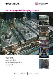
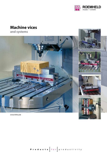
<strong>Machine</strong> <strong>vices</strong><br />
and systems<br />
www.hilma.de
... the standards for tool making, mould making, construction<br />
of jigs and fixtures and production<br />
Cost consciousness!<br />
A high quality level and mature technology at affordable prices. The basic<br />
product for your daily clamping tasks. Your safety: Absolute reliability thanks<br />
to mechanical-hydraulic power transmission, well-proven in practice.<br />
Your added value: Can be used together with the well-known HILMA<br />
interchangeable jaws and the extensive range of accessories.<br />
Versatile and flexible!<br />
The classic unit for high demands on quality and flexibility. Well-proven<br />
power transmission either mechanical-hydraulic or hydraulic for automation.<br />
Your benefit: The keyways and hole pattern are arranged for accommodating<br />
step jaws for extra large clamping ranges. Keyways across the width for<br />
rapid positioning on the machine platen. Can be used with the well-known<br />
HILMA interchangeable jaws and the extensive range of accessories.<br />
For the most exacting demands!<br />
Our premium product for even greater quality, process safety and precision.<br />
The benefits: Large capacity although with a compact overall length.<br />
Encapsulated power transmission system, base free from deformation, very<br />
precise linear guide and much more. Compatible with commercially available<br />
zero point clamping systems. Existing clamps from the HILMA range can<br />
be used. All this makes your investment sound for the future.<br />
Accessories and jaws<br />
Simply economical!<br />
An extensive range of quickly interchangeable jaws and convenient<br />
accessories guarantee exact positioning and clamping of both simple and<br />
complex workpieces. This significantly enlarges the possible range of uses<br />
of the clamping element. In many cases, the need for special fixtures can<br />
be dispensed with.<br />
Made by HILMA<br />
Efficient and cost reducing!<br />
A patented technique for cost-effective manufacture of 2, or optionally<br />
4 workpieces makes this product a unique means of cost reduction in the<br />
manufacture of small, medium and large batches. Compact overall<br />
dimensions, linear guide without play, one-side spindle operation and the<br />
3 rd hand function are further important advantages. Mechanical and hydraulic<br />
designs available.<br />
Light-weight and flexible!<br />
The standard fixture for a large number of workpieces with complex clamping<br />
contours, e.g. formed parts. Easy milling of stop, clamping and contact<br />
surfaces in aluminium jaws.<br />
Rapid change from one workpiece to another. Aluminium body with hardened<br />
steel guides ensures a low weight. In many cases, the need for special<br />
fixtures can be dispensed with.
Pages 4 - 5<br />
Pages 6 - 9<br />
Pages 10 - 11<br />
Pages 12 - 19<br />
Pages 20 - 23<br />
Pages 24 - 26<br />
Quickly and reliably!<br />
Page 27<br />
Maintenance service on the spot!<br />
3
Hydraulic machine vice<br />
EL mechanical-hydraulic<br />
Tap holes as a standard on both sides<br />
of the fixed jaw for precision<br />
workpiece stops<br />
Integral mechanicalhydraulic<br />
power<br />
transmission<br />
Interchangeable clamping ledges<br />
plain/serrated<br />
Guideways<br />
hardened<br />
and ground<br />
Recommended accessories:<br />
Angular drive (fig.)<br />
and selection of clamping<br />
force, 6 stages<br />
(optional extras)<br />
Resistant to deformation<br />
thanks to the optimised cross<br />
section of the base<br />
Rapid coarse adjustment<br />
of the clamping range by<br />
means of socket pin<br />
Clamping edge for clamping claws<br />
4
*<br />
For tool making, mould making, construction of jigs<br />
and fixtures and production<br />
The completely revised power transmission system requires<br />
minimum effort on the crank handle. An angular drive (optional extra)<br />
makes actuation easier, e.g. in the case of longitudinal clamping on the<br />
machine table. The optional selection of clamping force enables the force<br />
to be applied in 6 stages up to the maximum.<br />
d<br />
S1<br />
L max.<br />
Optional extra<br />
angular drive<br />
a<br />
g2<br />
c*<br />
SW<br />
t<br />
e*<br />
f<br />
*Tolerance ±0.01 mm<br />
Scope of supply:<br />
Standard reversible jaws plain/serrated,<br />
crank handle, operating manual<br />
EuroLine<br />
Not for use with a spherical base<br />
Type Part no. Jaw width a Clamping force Clamping width S1 Overall length L max. Weight<br />
(mm) (kN) (mm) (mm) kg<br />
EL100 9.3022.1113 100 25 205 464 18.5<br />
EL125 9.3023.1113 125 40 225 526 31.5<br />
EL160 9.3024.1113 160 50 309 684 58.5<br />
EL160L 9.3024.1313 160 50 509 884 75<br />
with angular drive<br />
Type<br />
Dimensions in mm<br />
b (mm) c d e f g2 t SW<br />
EL100 34 13 80 70 380 M12 x 18 24 14<br />
EL125 45 15 100 82 430 M12 x 18 27 17<br />
EL160 54 18 120 95 550 M20 x 27 27 19<br />
EL160L 54 18 120 95 750 M20 x 27 27 19<br />
Jaws and accessories see pages 12-17.<br />
We will be pleased to provide more details. Please contact info@hilma.de<br />
5
Hydraulic machine vice<br />
NC-M mechanical-hydraulic<br />
Tap holes as a standard<br />
on both sides of the<br />
fixed jaw for precision<br />
workpiece stop<br />
Guideways<br />
hardened and<br />
ground<br />
Keyways and tap holes<br />
for step jaw inserts giving<br />
very large clamping<br />
ranges<br />
Integral<br />
mechanicalhydraulic<br />
power<br />
transmission<br />
Recommended accessories:<br />
Angular drive (fig.),<br />
6-stage selection of<br />
clamping force and step<br />
jaw inserts (optional extras)<br />
Clamping edge<br />
for clamping claws<br />
Rapid coarse adjustment<br />
of the clamping range<br />
using the socket pin<br />
20 H 7 keyways in the longitudinal<br />
directon and across the width for<br />
quick positioning in accordance<br />
with NC requirements<br />
Resistant to deformation<br />
thanks to the optimised<br />
cross section of the base<br />
6
t<br />
b*<br />
For tool making, mould making, construction of jigs<br />
and fixtures and production<br />
The completely revised power transmission system requires minimum effort on<br />
the crank handle. An angular drive (optional extra) makes actuation easier, e.g.<br />
in the case of longitudinal clamping on the machine platen.<br />
The optional selection of clamping force (retrofitting possible) enables<br />
the clamping force to be applied in 6 stages up to the maximum.<br />
Special benefits by the possibility of exact positioning on all machine beds<br />
provided with grooves as well as optimum use of the machine travel and<br />
extension of the clamping range using step jaw inserts.<br />
L max.<br />
S3<br />
S2<br />
d S1 c*<br />
Optional extra<br />
step jaw inserts<br />
Optional extra<br />
angular drive<br />
a<br />
g2<br />
w*<br />
u**<br />
SW<br />
e*<br />
m**<br />
20H7<br />
20H7<br />
f<br />
*Tolerance ±0.01 mm<br />
**Tolerance ±0.02 mm<br />
Scope of supply:<br />
Standard reversible jaws plain/serrated,<br />
crank handle, operating manual<br />
Type Part no. Jaw width a Clamping force Clamping width (mm) Overall length L max. Weight<br />
(mm) kN S1 S2 S3 (mm) kg<br />
NC100M 9.3072.0203 100 25 205 330 386 464 18.5<br />
NC125M 9.3073.0203 125 40 225 363 431 526 31.5<br />
NC160M 9.3074.0203 160 50 309 503 573 684 58.5<br />
Type<br />
Dimensions in mm<br />
b c d e f g2 m SW t u w<br />
NC100M 34 13 80 70 380 M12 x 18 110 14 24 45 40<br />
NC125M 45 15 100 82 430 M12 x 18 115 17 27 58 53<br />
NC160M 54 18 120 95 550 M20 x 27 155 19 27 70 65<br />
Jaws and accessories see pages 12 - 17.<br />
We will be pleased to provide more details. Please contact info@hilma.de<br />
7
Hydraulic machine vice<br />
NC-H hydraulically operated<br />
Tap holes as a standard<br />
on both sides of the<br />
fixed jaw for precision<br />
workpiece stop<br />
Keyways and tap holes<br />
for step jaw inserts giving<br />
very large clamping ranges<br />
Pressure transducer for NC-H,<br />
e.g. hydraulic power unit<br />
Guideways<br />
hardened and<br />
ground<br />
Power<br />
stroke 5 (7)<br />
Clamping edge<br />
for clamping claws<br />
Rapid coarse adjustment<br />
of the clamping range<br />
using the socket pin<br />
20 H 7 keyways<br />
in longitudinal direction and across<br />
the width for quick positioning<br />
in accordance with NC requirements<br />
Resistant to deformation<br />
thanks to the optimised<br />
cross section of the base<br />
Operating pressure (bar)<br />
5% Clamping force 100%<br />
350<br />
300<br />
250<br />
200<br />
150<br />
100<br />
50<br />
0<br />
Clamping force infinitely<br />
variable on the power unit<br />
8
Druck<br />
t<br />
For use in semi- or fully automatic operation<br />
in series production<br />
Connection to a separate hydraulic pressure transducer, e.g.<br />
a hydraulic power unit. Coarse adjustment of the clamping<br />
range using the socket pin. Fine positioning against the<br />
workpiece and adjustment of the insertion tolerance manually<br />
using a lead screw.<br />
The clamping process is triggered manually or by foot-operated<br />
switch or, in the case of a fully automatic working cycle, by an<br />
electrical control pulse.<br />
erreicht<br />
Spannen<br />
Lösen<br />
S3<br />
L max.<br />
Optional extra<br />
step jaw inserts<br />
d S1 c*<br />
S2<br />
2x G1/4“<br />
a<br />
g2<br />
e*<br />
b*<br />
w*<br />
u**<br />
SW<br />
m**<br />
20H7<br />
20H7<br />
f<br />
*Tolerance ±0.01 mm<br />
**Tolerance ±0.02 mm<br />
Scope of supply:<br />
Standard reversible jaws plain/serrated,<br />
crank handle, operating manual<br />
Type Part no. Jaw width Clamping Operating Power Oil con- Clamping width Overall length Weight<br />
a force pressure stroke sumption S1 S2 S3 L max.<br />
(mm) kN bar (mm) cm 3 (mm) (mm) (mm) (mm) kg<br />
NC100H 9.3082.0203 100 25 350 5 5 209 334 390 456 18.5<br />
NC125H 9.3083.0203 125 40 350 5 7 228 366 434 518 31.5<br />
NC160H 9.3084.0203 160 63 350 7 14 314 508 578 675 58.5<br />
Type<br />
Dimensions in mm<br />
b c d e f g2 m SW t u w<br />
NC100H 34 13 80 70 380 M12 x 18 110 8 24 45 40<br />
NC125H 45 15 100 82 430 M12 x 18 115 8 27 58 53<br />
NC160H 54 18 120 95 550 M20 x 27 155 10 27 70 65<br />
Jaws and accessories see pages 12 - 17.<br />
We will be pleased to provide more details. Please contact info@hilma.de<br />
9
Hydraulic machine vice<br />
KNC mechanical-hydraulic<br />
Encapsulated<br />
power transmission*<br />
Universal use of almost all HILMA jaw inserts<br />
such as standard, QIS etc.<br />
(see pages 14-15 and 18-19).<br />
Step jaws, reversible<br />
Tap holes for connection<br />
to existing HILMA<br />
clamping jaw systems<br />
Recommended accessories:<br />
Angular drive (fig.),<br />
6-stage selection of<br />
clamping force,<br />
locking device<br />
Clamping edge<br />
and 20 H7 reference<br />
keyways on the face for<br />
vertical clamping applications<br />
(universal type)<br />
20 H7 keyways<br />
Rapid coarse<br />
adjustment<br />
of the clamping range<br />
using the socket pin<br />
Precision<br />
linear guide<br />
KNC Universal<br />
horizontal arrangement<br />
KNC Universal<br />
vertical arrangement<br />
KNC Universal<br />
lateral arrangement<br />
* The perfect arrangement:<br />
The power transmission and the spindle drive are integrated<br />
into the slide body and are fully encapsulated.<br />
10
For tool making, mould making, construction of jigs and fixtures and production<br />
This new development meets the most exacting demands on clamping quality. The mechanical-hydraulic power<br />
transmission and the spindle drive are integrated into the slide body and are fully encapsulated. Easy, user-friendly<br />
manual clamping using the crank handle. 6-stage clamping force selection and angular drive are available as optional<br />
extras which may be retrofitted. The non deformable steel base with hardened and ground guideways and the linear<br />
guide with almost no play guarantee maximum precision.<br />
KNC Standard horizontal arrangement – with 20 H7 keyway<br />
S2<br />
l2**<br />
S1<br />
t<br />
Tap holes for HILMA<br />
standard clamping jaws<br />
h1<br />
a*<br />
SW<br />
H<br />
Scope of supply:<br />
crank handle,<br />
operating manual<br />
h*<br />
p1**<br />
p2**<br />
L<br />
20 H7 (4x)<br />
l1<br />
h2<br />
B<br />
20 H7<br />
*Tolerance ±0.01 mm<br />
**Tolerance ±0.02 mm<br />
KNC Standard KNC Universal Jaw width Clamping force Clamping width Length Weight<br />
Type Part no. Part no. a (mm) kN S (mm) S1 (mm) L (mm) kg<br />
KNC100 9.3152.0131 9.3152.0141 100 25 90 - 230 0 - 140 300 17.0<br />
KNC125 9.3153.0131 9.3153.0141 125 40 114 - 354 0 - 240 440 39.5<br />
KNC160 9.3154.0131 9.3154.0141 160 50 136 - 436 0 - 300 540 72.0<br />
Dimensions (mm) KNC Standard and Universal<br />
Dimensions (mm) KNC Universal<br />
Type B H a h h1 h2 l1 l2 p1 p2 t SW p3 p4 p5 counter bore<br />
KNC100 100 123 27 90 33 16 45,4 46 14 104 4 14 28,5 70 2 x 80 3 x KM12<br />
KNC125 125 144 28 100 44 16 53,5 53 17 167 5 17 30 120 2 x 100 3 x KM12<br />
KNC160 160 168 37 115 53 20 53,5 64 16 206 6 17 36 170 3 x 100 4 x KM12<br />
KNC Universal for horizontal, vertical and lateral arrangement, with 20 H7 keyway, 20 H7 reference keyway on the face,<br />
threaded fastening holes in the base and a gas pressure spring for load relief of the slide in vertical arangement.<br />
p4 p5 p5<br />
Countersinking<br />
l2**<br />
S1<br />
t<br />
Tap holes for HILMA<br />
standard clamping jaws<br />
h* h1<br />
p3**<br />
20 H7<br />
h2<br />
p1**<br />
p2**<br />
L<br />
20 H7<br />
a*<br />
L1<br />
SW<br />
H<br />
h2<br />
B<br />
20 H7<br />
*Tolerance ±0.01 mm<br />
**Tolerance ±0.02 mm<br />
Jaws and accessories see pages 12 - 15 and 18 - 19.<br />
We will be pleased to provide more details. Please contact info@hilma.de<br />
11
Accessories<br />
Precision workpiece stop for types EL, NC, KNC<br />
pivoting, rapid fastening. Adjustment in 2 levels.<br />
a<br />
d<br />
Part no. for jaw width a b c d<br />
9.3291.0201 100 / 125 / 160 M 12 61 95 46<br />
9.3291.0401 only EL / NC 160 M 20 81 124 66<br />
c<br />
Angular drive for types EL, NC-M<br />
for machine <strong>vices</strong> and clamping systems of mechanical-hydraulic<br />
design. May be used when normal operation is difficult or even<br />
impossible. Ideal for retrofitting.<br />
Part no. for jaw width SW b crank radius<br />
9.3294.0505 100 10 39 125<br />
9.3294.0605 125 10 43 125<br />
9.3294.0705 160 10 46 125<br />
b<br />
Angular drive for type KNC<br />
without locking device, for subsequent fitting<br />
Part no. for type L B H k SW<br />
9.3294.0251 KNC100 85 54 76 22.5 14<br />
9.3294.0352 KNC125/ KNC160 90 62 82 24 14<br />
H<br />
B<br />
L<br />
SW<br />
k<br />
Lock<br />
optional extra<br />
Locking device for type KNC angular drive<br />
for subsequent fitting<br />
Part no.<br />
for type<br />
9.3152.0529 KNC100<br />
9.3153.0529 KNC125/ KNC160<br />
Locking device for type KNC<br />
for subsequent fitting<br />
Part no.<br />
for type<br />
9.3152.0528 KNC100<br />
9.3153.0528 KNC125/ KNC160<br />
6-step clamping force preselection for types EL, NC-M<br />
Retrofit possible, for mechanical-hydraulic design<br />
Part no. for jaw width<br />
9.3762.0100 100<br />
9.3762.0125 125<br />
9.3762.0160 160<br />
Clamping force preselection for type KNC<br />
with locking device, for subsequent fitting<br />
Part no.<br />
for type<br />
9.3762.0251 KNC100<br />
9.3762.0351 KNC125/ KNC160<br />
12
Load cell for types EL, NC, KNC<br />
for regular checks of the clamping force of hydraulic and mechanical<br />
clamping elements<br />
Part no. Indicating for jaw<br />
range kN a b c d width<br />
2.9501.0001 0 - 60 88 150 29 37 100/125/160<br />
d<br />
a<br />
c<br />
Set of keyblocks DIN 6323, loose for types NC, KNC<br />
For precise alignment of the clamping device on the machine bed the<br />
keyblocks are inserted laterally<br />
Part no.<br />
for 2 OFF = 1 set<br />
Slot in the bed<br />
a<br />
9.3917.4121 14 h6<br />
9.3917.4141 18 h6<br />
Example of application<br />
32 14<br />
0,02 A<br />
20 h6<br />
a<br />
5,5<br />
A<br />
Set of keyblocks DIN 508 for types EL, NC, KNC<br />
a<br />
Part no.<br />
for 4 OFF = 1 set a b g h k<br />
9.3777.3211 14 22 M 12 16 8<br />
9.3777.3231 18 28 M 12 20 10<br />
9.3777.3311 18 28 M 16 20 10<br />
h<br />
b<br />
b<br />
g<br />
k<br />
Set of clamping claws with screws for types EL, NC<br />
7 16<br />
Part no.<br />
Cap screw<br />
for 4 OFF = 1 set h DIN 912<br />
9.3777.2011 24 M 12 x 45 8.8<br />
9.3777.3011 27 M 12 x 45 8.8<br />
9.3777.3021 27 M 16 x 50 8.8<br />
h<br />
40<br />
50<br />
Set of clamping claws with screws for type KNC<br />
Part no. for type Slot Cap screw<br />
for 4 OFF b h DIN 912<br />
KNC100<br />
9.3777.3051 KNC125 14 6 16 M 12 x 30 8.8<br />
KNC100<br />
9.3777.3061 KNC125 18 6 16 M 16 x 40 8.8<br />
9.3777.3031 KNC160 14 7 20 M 12 x 35 8.8<br />
9.3777.3041 KNC160 18 7 20 M 16 x 40 8.8<br />
h<br />
b<br />
40<br />
50<br />
all dimensions in mm<br />
We will be pleased to provide more details. Please contact info@hilma.de<br />
13
Standard jaws<br />
Step jaw insert for type NC<br />
for achieving very large clamping widths.<br />
for fixed jaw for slide<br />
Part no. Part no. a c d e h l m p<br />
9.3284.0201 9.3284.1201 100 11.5 6 34 6.5 48 60 10h6<br />
9.3284.0301 9.3284.1301 125 14 6 40 9 58 65 12h6<br />
9.3284.0401 9.3284.1401 160 17 8 43 12 64 88 18h6<br />
a<br />
m**<br />
5<br />
4<br />
c*<br />
d 5<br />
* = Tolerance ± 0.01 mm,<br />
** = Step jaw insert for slide only<br />
p<br />
e* 4<br />
h*<br />
Precision step jaw for types EL, NC, KNC<br />
for clamping rectangular workpieces without parallel pads.<br />
These jaws allow holes to be drilled near the edge. Used in pairs only.<br />
a<br />
f*<br />
g*<br />
Part no. a b c d e f g<br />
5.2082.0001 100 34 29 10 19 15 11<br />
5.2082.0002 125 45 39 13 25 20 16<br />
5.2082.0003 160 54 45 15 25 20 16<br />
b<br />
* = Tolerance ± 0.01 mm<br />
e*<br />
d*<br />
c*<br />
Pendulum jaw for types EL, NC, KNC<br />
for clamping one workpiece with nonparallel clamping surfaces<br />
or two workpieces with different tolerances.<br />
b<br />
a<br />
d<br />
Part no. a b c d<br />
8.3711.0208 100 34 35 16<br />
8.3711.0308 125 45 50 22<br />
8.3711.0408 160 54 55 26<br />
c<br />
Vee jaw for types EL, NC, KNC<br />
for horizontal and vertical clamping of cylindrical workpieces.<br />
Part no. a b b1 c d<br />
5.3030.0002 100 34 19 17 8 - 35<br />
5.3030.0003 125 45 27 19 10 - 50<br />
5.3030.0004 160 54 32 21 12 - 60<br />
b<br />
a<br />
Vee tolerance ± 0.01 mm<br />
c<br />
d<br />
120°<br />
b1<br />
Clamping jaw, soft for types EL, NC, KNC<br />
16 MnCr5, supplied oversize, for preparation of specific jaws by the customer.<br />
a<br />
c<br />
Part no. a b c<br />
5.2055.0097 100 36 20<br />
5.2055.0098 125 47 25<br />
5.2055.0099 160 56 30<br />
b<br />
Clamping jaw extra high for types EL, NC<br />
for the safe clamping of high workpieces.<br />
Used as single jaw or in pairs.<br />
b<br />
a<br />
c<br />
e<br />
Part no. a b c d e<br />
9.3283.0201 100 58 25 25 60<br />
9.3283.0301 125 75.5 32 32 74<br />
9.3283.0401 160 92.5 40 40 100<br />
* = Tolerance ± 0.01 mm<br />
d*<br />
Clamping jaw extra large for types EL, NC, KNC<br />
for the safe clamping of workpieces exceeding the standard jaw width.<br />
Used in pairs only.<br />
Part no. a b c d<br />
5.2058.1025 100 34 13 125<br />
5.2058.1026 125 45 15 160<br />
5.2058.1027 160 54 20 200<br />
a<br />
d<br />
* = Tolerance ± 0.01 mm<br />
b*<br />
c*<br />
14<br />
all dimensions in mm
QIS Jaws<br />
b<br />
a<br />
QIS base jaw, with permanent magnets<br />
for types EL, NC, KNCC<br />
Part no. a b<br />
9.3771.0201 100 34<br />
9.3771.0301 125 45<br />
9.3771.0401 160 54<br />
Quick insert system with<br />
downthrust effect:<br />
The base jaws are fastened to the<br />
slide and to the fixed jaw using screws.<br />
The jaw inserts can be inserted and<br />
removed swiftly. They are kept in place<br />
by two permanent magnets.<br />
QIS jaw insert, plain for types EL, NC, KNC<br />
b<br />
a<br />
c*<br />
Part no. a b c<br />
8.3771.1201 100 34 21<br />
8.3771.1301 125 45 26<br />
8.3771.1401 160 54 31<br />
Fasten the base<br />
jaws to the<br />
slide and to the<br />
fixed jaw<br />
(one-off task).<br />
1<br />
* = Tolerance ± 0.01 mm<br />
b<br />
a<br />
* = Tolerance ± 0.01 mm<br />
c*<br />
QIS jaw insert, serrated for types EL, NC, KNC<br />
Part no. a b c<br />
8.3771.2201 100 34 21<br />
8.3771.2301 125 45 26<br />
8.3771.2401 160 54 31<br />
Slide the<br />
desired jaw<br />
inserts against<br />
the base jaws.<br />
2<br />
b<br />
a<br />
c<br />
QIS jaw insert, crowned for types EL, NC, KNC<br />
Part no. a b c<br />
8.3771.3211 100 32.5 23<br />
8.3771.3311 125 43 27.3<br />
8.3771.3411 160 51 31.9<br />
The permanent<br />
magnets and a<br />
guide pin keep<br />
the jaw insert<br />
in its basic<br />
position.<br />
3<br />
b<br />
a<br />
* = Tolerance ± 0.01 mm<br />
d*<br />
c*<br />
g<br />
e*<br />
f*<br />
QIS jaw insert, stepped<br />
for types EL, NC, KNC<br />
Part no. a b c d e f g<br />
8.3771.4201 100 34 21 25 10 29 4<br />
8.3771.4301 125 45 26 30 13 39 5<br />
8.3771.4401 160 54 31 35 15 45 5<br />
For changing<br />
the jaw insert,<br />
pull it upwards<br />
until the guide<br />
pin engages<br />
in the slot.<br />
4<br />
b<br />
a<br />
e H7<br />
* = Tolerance<br />
± 0.01 mm<br />
c*<br />
f<br />
120°<br />
30<br />
d*<br />
QIS jaw insert, prismatic<br />
for types EL, NC<br />
Part no. Ø from to a b c d e f<br />
8.3771.5201 8 - 35 100 34 53 19 78 28<br />
8.3771.5301 10 - 50 125 45 58 27 98 34.2<br />
8.3771.5401 12 - 60 160 54 60 32 125 37<br />
Slightly tilt the<br />
jaw insert to<br />
overcome the<br />
retention force<br />
of the permanent<br />
magnets.<br />
5<br />
b<br />
a<br />
c<br />
QIS jaw insert, soft<br />
for types EL, NC<br />
Part no. a b c e<br />
8.3771.7201 100 34 30 78<br />
8.3771.7301 125 45 36.5 98<br />
8.3771.7401 160 54 47 125<br />
For installing a<br />
new jaw insert,<br />
proceed as<br />
described<br />
in 2 and 3.<br />
6<br />
e H7<br />
We will be pleased to provide more details. Please contact info@hilma.de<br />
all dimensions in mm<br />
15
SlimFlex jaw system<br />
Optimum machining of<br />
workpieces on three sides in<br />
one clamping operation<br />
The SlimFlex jaw system allows<br />
3-side machining of centrally<br />
clamped workpieces with dimensions<br />
less than the jaw width of the<br />
clamping device.<br />
Standard<br />
Scale for rough adjustment<br />
Space for the<br />
work spindle<br />
QIS<br />
Retaining pieces keep the workpiece<br />
off the base jaw, which provides optimum<br />
access from three sides for the<br />
work spindle.<br />
Space for the<br />
work spindle<br />
Adjustable<br />
retaining pieces<br />
The retaining<br />
pieces<br />
are reversible<br />
Base jaw in<br />
Q.I.S. design<br />
Perfect positioning<br />
and adjustment<br />
in a few steps:<br />
The blank is approx.<br />
2 mm larger than<br />
the finished<br />
workpiece.<br />
SlimFlex jaw system, standard design for types EL, NC<br />
20<br />
a<br />
l<br />
m<br />
b<br />
Stepped retaining piece<br />
c1<br />
12<br />
5<br />
e<br />
h1<br />
3<br />
c2 2<br />
25<br />
15<br />
3<br />
h2<br />
30<br />
wide<br />
n<br />
Retaining piece<br />
C45 soft<br />
Adjust the jaws<br />
approx. 2 mm<br />
below the finished<br />
dimensions.<br />
Place the workpiece<br />
by eye in a central<br />
position and<br />
clamp it.<br />
Proceed to 3-side<br />
machining.<br />
Jaw width Part no. Part no. Part no.<br />
a SlimFlex jaw system without SlimFlex jaw system with Retaining piece<br />
stepped retaining pieces stepped retaining pieces C45 soft<br />
100 9.3714.0202 9.3714.0212 5.5050.0123<br />
125 9.3714.0302 9.3714.0312 5.5050.0099<br />
160 9.3714.0402 9.3714.0412 5.5050.0099<br />
Jaw width<br />
Dimensions in mm<br />
a b c1 c2 e h1 h2 l m n<br />
100 34 30 ± 0.02 33 ± 0.02 10 24 ± 0.02 31 ± 0.02 78 H7 11 30<br />
125 45 32 ± 0.02 35 ± 0.02 15 30 ± 0.02 42 ± 0.02 98 H7 16 40<br />
160 54 34 ± 0.02 37 ± 0.02 15 39 ± 0.02 51 ± 0.02 125 H7 16 40<br />
SlimFlex jaw system, QIS design for types EL, NC<br />
20<br />
a<br />
l<br />
m<br />
b<br />
c3 5<br />
c4 2<br />
25<br />
12<br />
Magnet<br />
15<br />
QIS base jaw<br />
e<br />
h1<br />
3<br />
h2 3<br />
Interchangeable jaw<br />
30<br />
wide<br />
n<br />
Retaining piece<br />
C45 soft<br />
Jaw width Part no. Part no. Part no. Part no.<br />
a Interchangeable jaw Interchangeable jaw Retaining piece Q.I.S. base jaw<br />
without stepped retaining pieces with stepped retaining pieces C45 soft<br />
100 9.3771.9201 9.3771.9211 5.5050.0123 9.3771.0201<br />
125 9.3771.9301 9.3771.9311 5.5050.0099 9.3771.0301<br />
160 9.3771.9401 9.3771.9411 5.5050.0099 9.3771.0401<br />
Jaw width<br />
Dimensions in mm<br />
a b c3 c4 e h1 h2 l m n<br />
100 34 45 ± 0.02 48 ± 0.02 10 24 ± 0.02 31 ± 0.02 78 H7 11 30<br />
125 45 50 ± 0.02 53 ± 0.02 15 30 ± 0.02 42 ± 0.02 98 H7 16 40<br />
160 54 55 ± 0.02 58 ± 0.02 15 39 ± 0.02 51 ± 0.02 125 H7 16 40<br />
For type KNC, see page 19<br />
16
SMV jaws<br />
Stop pin<br />
displaceable<br />
Clamping bar interchangeable<br />
Clamping bar positioning pin<br />
Efficient multiple clamping<br />
using floating central jaws<br />
Central jaw made from AL,<br />
hard anodized<br />
Lower grip<br />
Using floating central jaws for multiple<br />
clamping, the working area in an NC<br />
machine is utilized to the maximum.<br />
The resulting reduction in tool changes<br />
and travel contributes to a significant<br />
reduction in cost.<br />
Can be combined with all HILMA<br />
clamping systems of types EL, NC.<br />
a<br />
f1<br />
e<br />
Workpiece without/with<br />
clamping edge<br />
Floating central jaws, standard design for types EL, NC<br />
f2 ±0.02<br />
b3<br />
Efficient and cost-effective:<br />
Existing or new HILMA machine <strong>vices</strong><br />
can be changed from single to multiple<br />
clamping systems at low cost and with<br />
minimum retrofitting work.<br />
c1 -0.01<br />
Stop pin<br />
displaceable<br />
Workpiece without/ with<br />
„lost head“<br />
Ød<br />
- the lower grip prevents workpieces<br />
from rearing up<br />
- longer machine running times<br />
allow to operate several machines<br />
- complex workpieces can be milled<br />
all around<br />
- all workpieces are clamped with<br />
the same clamping force<br />
- optimum utilization of the working<br />
area by dense workpiece arrangement<br />
- determination of the lateral workpiece<br />
position by displaceable<br />
stop pins<br />
Clamping bar<br />
a<br />
Clamping bar positioning pin<br />
c2<br />
b2<br />
b2<br />
Central jaw<br />
g<br />
Ø6<br />
b1<br />
Precision step jaw for<br />
slide and fixed jaw.<br />
For dimensions,<br />
see standard jaws<br />
After finish-machining, the „lost head“<br />
is separated from the workpiece using a<br />
disk milling cutter.<br />
Jaw Part no. Part no. Part no.<br />
width Central jaw with Clamping bar Precision Dimensions in mm<br />
a clamping bar step jaw b1 b2 b3 c1 c2 Ød e f1 f2 g<br />
100 9.3715.0211 9.3715.1201 5.2082.0001 48 29 5 12 20 3 13 52 78 M5<br />
125 9.3715.0311 9.3715.1301 5.2082.0002 61 39 6 16 26 4 16 64 96 M5<br />
160 9.3715.0411 9.3715.1401 5.2082.0003 70 45 9 20 30 5 20 80 120 M6<br />
We will be pleased to provide more details. Please contact info@hilma.de<br />
The clamping edge is milled off in the 2nd<br />
clamping step.<br />
17
f<br />
b<br />
e<br />
a -0,01<br />
t<br />
h<br />
c<br />
i<br />
j<br />
i<br />
j<br />
f<br />
f<br />
f<br />
l<br />
j<br />
KNC jaws<br />
G3 for fine step<br />
Reversible step jaw (figure shows fixed jaw)<br />
1st side with fine step accommodation, 2nd side with a hole pattern for<br />
HILMA QIS jaw system or for fastening rapidly changeable precise step bars.<br />
G2 for HILMA standard jaws<br />
G1<br />
i<br />
(l1 at movable jaw)<br />
Part no. Part no. Dimensions in mm<br />
Fixed jaw Mobile jaw l l1 b h a c e f t i j G1 G2 G3<br />
9.3152.6903 9.3152.6904 80 60 100 33 27 8 65 11 4 – – M12/18 M6/8 –<br />
9.3153.6903 9.3153.6904 100 80 125 44 28 8 80 14 5 76 5 M12/18 M8/11 M4/6<br />
9.3154.6903 9.3154.6904 120 100 160 53 37 9 100 17 6 76 5 M12/18 M10/12 M4/6<br />
Precise step bars for reversible step jaw and block jaw, hardened<br />
b<br />
e<br />
h ±0,01<br />
h1 ±0,01<br />
l<br />
Part no. Part no. Dimensions in mm<br />
fine step h fine step h1 l b h h1 e f<br />
9.3152.6915 9.3152.6916 5 100 28 23.5 65 11<br />
9.3153.6915 9.3153.6916 5 125 39 34 80 14<br />
9.3154.6915 9.3154.6916 5 160 48 43 100 17<br />
hard-metal coating<br />
on one side (l1 at movable jaw)<br />
b<br />
l<br />
e<br />
G1<br />
G2 for HILMA standard jaws<br />
h<br />
Block jaw, hardened (figure shows fixed jaw)<br />
1 st side hard-metal coated, 2 nd side ground to be plain, with hole<br />
pattern matching the HILMA QIS jaw system and standard jaws<br />
Part no. Part no. Dimensions in mm<br />
Fixed jaw Mobile jaw l l1 b h e f G1 G2<br />
9.3152.6901 9.3152.6902 80 60 100 33.5 65 11 M12/18 M6/8<br />
9.3153.6901 9.3153.6902 100 80 125 44 80 14 M12/18 M8/11<br />
9.3154.6901 9.3154.6902 120 100 160 53 100 17 M12/18 M10/12<br />
b<br />
l<br />
f = max.<br />
milling depth<br />
Block jaw soft (figure shows fixed jaw)<br />
non-hardened, for milling workpiece contours,<br />
steps with stops etc.. Material 42CrMo4<br />
h<br />
Part no. Part no. Dimensions in mm<br />
Fixed jaw Mobile jaw l l1 b h f<br />
9.3152.6905 9.3152.6906 90 70 100 44 27<br />
9.3153.6905 9.3153.6906 110 90 125 54 35<br />
9.3154.6905 9.3154.6906 130 110 160 63 37<br />
a ±0.01<br />
d<br />
e<br />
t<br />
G1<br />
l<br />
(l1 at movable jaw)<br />
f<br />
b<br />
c ±0.01<br />
insert changeable<br />
Clamping jaw, extra high with changeable insert, hardened (figure shows fixed jaw)<br />
Use locking device!<br />
Whether for compensating for non-parallel clamping surfaces, powerful clamping in the case of<br />
small clamping edge or for providing different precise step accommodations: just change the<br />
bar to create a multitude of different jaw versions. Standard insert: 1 st side grip texture, 2 nd side<br />
plain for precise steps. Changeable inserts are easily changed and can be designed, with certain<br />
limits, individually.<br />
Part no. Part no. Dimensions in mm<br />
Fixed jaw Mobile jaw l l1 b a c e f i j t G1<br />
9.3152.6911 9.3152.6912 84 63 100 37 52 65 4.5 2.5 4 3 M12/18<br />
9.3153.6911 9.3153.6912 100 80 125 40 55 80 4.5 2.5 4 3 M12/18<br />
18
l<br />
f<br />
f<br />
j<br />
i<br />
j<br />
a ±0.01<br />
i<br />
j<br />
d<br />
e<br />
t<br />
G1<br />
l<br />
(l1 at movable jaw)<br />
f<br />
k<br />
b<br />
c ±0.01<br />
insert reversible<br />
Clamping jaw, extra high with changeable insert hardened, various widths.<br />
(Figure shows fixed jaw)<br />
Use locking device!<br />
Whether for compensating for non-parallel clamping surfaces, powerful clamping in the case of<br />
small clamping edge or for providing different precise step accommodations: just change the bar<br />
to create a multitude of different jaw versions. Standard insert: 1st side grip texture, 2nd side plain<br />
for precise steps. Changeable inserts are easily changed and can be designed, with certain limits,<br />
individually.<br />
Part no. Part no. Dimensions in mm<br />
Fixed jaw Mobile jaw l l1 b a c e f i j k t G1<br />
9.3152.6913 9.3152.6914 84 63 100 37 52 6 4.5 2.5 4 62 3 M12/18<br />
9.3153.6913 9.3153.6914 100 80 125 40 55 6 4.5 2.5 4 75 3 M12/18<br />
a ±0.01<br />
t<br />
l<br />
G for grip insert<br />
h<br />
i<br />
G3 for fine step<br />
Pendulum jaw<br />
for compensation of non-parallel clamping surfaces, saw cuts<br />
or non-parallel surfaces on drawn materials<br />
e<br />
b<br />
Part no.<br />
Dimensions in mm<br />
Fixed jaw l b h a e f i j t G G1<br />
9.3153.6908 83 125 44 28 105 35 76 5 5 10 M4/6<br />
9.3154.6908 104 160 53 37 140 44 76 5 6 10 M4/6<br />
n<br />
T-slot DIN 650<br />
l<br />
(l1 at movable jaw)<br />
b h<br />
G2<br />
for HILMA standard jaws<br />
e<br />
Scale 1 mm<br />
for rough adjustment<br />
SlimFlex clamping jaw (figure shows fixed jaw)<br />
e.g. for working with clamping base. Gives free room for spindle and tool. Available with step jaws<br />
as well as with prismatic and soft jaws.<br />
Part no. Part no. Dimensions in mm<br />
Fixed jaw Mobile jaw l l1 b h e f n G1 G2<br />
9.3152.6909 9.3152.6910 80 60 100 33.5 65 11 12 M8/14 M6/8<br />
9.3153.6909 9.3153.6910 100 80 125 44 80 14 14 M12/18 M8/11<br />
9.3154.6909 9.3154.6910 120 100 160 53 100 17 14 M12/18 M10/12<br />
l<br />
h<br />
b<br />
SlimFlex insert, soft<br />
Part no. Dimensions in mm for<br />
l b h jaw width<br />
9.3285.8014 60 30 23 100<br />
9.3285.8009 78 30 23 125 / 160<br />
t<br />
c<br />
b<br />
SlimFlex insert, stepped<br />
a ±0,01<br />
h<br />
Part no. Dimensions in mm for<br />
a b c h t jaw width<br />
9.3285.8013 8 23 50 23 5 100<br />
9.3285.8010 8 28 60 23 5 125 / 160<br />
b<br />
SlimFlex insert, prismatic<br />
h<br />
120° clamping area Ø s<br />
Part no. Dimensions in mm for<br />
l b h s jaw width<br />
9.3285.8012 60 100 18 50-140 100<br />
9.3285.8011 80 125 18 60-150 125 / 160<br />
We will be pleased to provide more details. Please contact info@hilma.de<br />
19
Made by HILMA<br />
Double clamping system<br />
mechanically operated DS-M, hydraulically operated DS-H<br />
Compact and user-friendly for two or optionally four workpieces (DS 125).<br />
Simple jaw<br />
change ensured<br />
by screwed<br />
connections<br />
Dense workpiece accommodation Floating central jaws for DS 125<br />
for accommodating max. 4 workpieces<br />
to prevent bridging<br />
3 rd hand function,<br />
easy adjustment of<br />
the clamping ranges<br />
and of the<br />
insertion space<br />
Spindle area encapsulated<br />
optimum protection against<br />
chips and coolant<br />
Thread for<br />
workpiece stop<br />
Clamping edge for<br />
clamping claws, optional<br />
fastening using internal grid<br />
holes. Vertical arrangement<br />
on request.<br />
Hydraulic cylinder for<br />
connection to a separate<br />
pressure transducer, e.g. a<br />
hydraulic power unit<br />
Oil port G 1/4” vertical (DS100/125)<br />
Oil port G 1/4” axial (DS125)<br />
Highly efficient for the<br />
production of small, medium<br />
and large batches in manual,<br />
semiautomatic or automatic<br />
operation.<br />
For an individual production of<br />
small and medium batches:<br />
DS double clamping system, mechanically<br />
operated for efficient<br />
machining of workpieces having<br />
the same or different dimensions.<br />
Manual clamping / unclamping<br />
preferably using a torque wrench<br />
with selectable clamping force.<br />
For the production of medium-sized and large batches:<br />
DS double clamping system, hydraulically operated for efficient machining<br />
of workpieces with short cycle times. Also suitable for an arrangement in rows for<br />
clamping workpieces which require several clamping points. Can be automated.<br />
20
Double clamping system<br />
DS 100 hydraulic and mechanical<br />
100 -0,1<br />
Hydraulic version<br />
Lubrication nipple<br />
18H7<br />
80 100 80<br />
18H7<br />
M6/10 deep 8x<br />
7<br />
Mechanical<br />
version<br />
6<br />
227 - 334<br />
1<br />
4<br />
70 ±0,02<br />
24<br />
200<br />
150 - 266<br />
5<br />
1<br />
4<br />
81 - 156 40 - 120<br />
4 2<br />
4<br />
SW13<br />
20<br />
Oil port G 1/4<br />
58<br />
420<br />
22<br />
46 - 126 10 - 90<br />
4 3<br />
4<br />
Positioning<br />
hole<br />
Ø4E8 5 deep<br />
40<br />
78<br />
36<br />
60<br />
M10/17 deep<br />
Locking screw<br />
3 rd hand<br />
DS 100 mechanical hydraulic<br />
Clamping force / torque 25 kN / 55 Nm 25 kN / 400 bar<br />
Clamping stroke / slide 44 mm 44 mm<br />
Power stroke / - 10 mm /8 cm 3<br />
oil consumption<br />
5 mm/side<br />
Weight without clamping jaws 19.5 kg 21 kg<br />
Part no. standard version 9.3665.0101 9.3685.0101<br />
Part no.<br />
Planned version for customerspecific<br />
positioning and fastening<br />
on request<br />
Item Part no. Designation<br />
1 9.3791.5140 Guide plate<br />
2 9.3791.5111 Central step jaw 26 mm<br />
3 9.3791.5121 Central step jaw 86 mm<br />
4 9.3791.5211 Central reversible jaw<br />
5 9.3791.5341 Step jaw, fixed<br />
6 9.3791.5311 Step jaw, fixed<br />
The standard clamping jaws enable 1 or 2<br />
workpieces having the same or different<br />
dimensions to be accommodated.<br />
SW14<br />
16<br />
10<br />
24<br />
50<br />
40<br />
Set of clamping claws<br />
4 clamping claws with 4 screws DIN 912<br />
Part no. 9.3777.2011<br />
for T-slot 14 mm<br />
Torque wrench<br />
Part no. 9.3792.6610<br />
20 - 120 Nm with reversible ratchet<br />
and square 1/2” with ball lock<br />
SW 14 Socket wrench 1.3124.0020 mech.<br />
DS 100 standard jaws,<br />
case-hardened and ground<br />
with 8 mm steps (free space<br />
for tools and chips).<br />
Supplied including<br />
fastening screws.<br />
KM 10 mounting holes for all jaws,<br />
all dimensions in mm<br />
26 -0,02<br />
5<br />
100<br />
8<br />
18f7<br />
96<br />
15,1 -0.05<br />
25 -0,01<br />
60<br />
5<br />
M4 / 6 deep (4x)<br />
Central step jaw<br />
Part no. 9.3791.5111<br />
76 ±0,01<br />
5<br />
15,1 -0.05<br />
100<br />
60<br />
8<br />
100<br />
5 86 -0,02<br />
18f7<br />
96<br />
15,1 -0.05<br />
25 -0,01<br />
60<br />
5<br />
M4 / 6 deep (4x)<br />
Central step jaw<br />
Part no. 9.3791.5121<br />
8<br />
5 26<br />
5<br />
15,1 -0,05<br />
60<br />
26<br />
5<br />
15,1 -0,05<br />
60<br />
18f7<br />
72<br />
25 -0,01<br />
5<br />
5<br />
5<br />
18f7<br />
18f7<br />
M4 / 6 deep (4x)<br />
88<br />
M4 / 6 deep (2x) 72<br />
M4 / 6 deep (2x)<br />
25 -0,01<br />
25 -0,01<br />
100<br />
Step jaw, reversible<br />
Part no. 9.3791.5211<br />
78<br />
Step jaw, fixed<br />
Part no. 9.3791.5341<br />
100<br />
78<br />
Step jaw, fixed<br />
for maximum clamping range<br />
Part no. 9.3791.5311<br />
96<br />
max.<br />
milling depth<br />
84<br />
max.<br />
milling depth<br />
96<br />
40<br />
100<br />
18f7<br />
22<br />
Underside<br />
hardened<br />
Positioning pin Ø4 m6<br />
Central jaw, soft<br />
Material C45<br />
Part no. 9.3791.5411<br />
40<br />
100<br />
18f7<br />
22<br />
Underside hardened<br />
Reversible jaw, soft<br />
Material C45<br />
Part no. 9.3791.5421<br />
16<br />
100<br />
18f7<br />
Guide plate<br />
Part no. 9.3791.5140<br />
We will be pleased to provide more details. Please contact info@hilma.de<br />
21
Made by HILMA<br />
Double clamping system<br />
DS125 hydraulic and mechanical<br />
Double clamping system DS 125, overall length 430 mm, hydraulic and mechanical<br />
186 - 350<br />
7<br />
1<br />
4<br />
146 - 270<br />
5<br />
1<br />
4<br />
125 -0,1<br />
Hydraulic version<br />
Lubrication nipple<br />
20H7<br />
180<br />
20H7<br />
M12/17 deep 4x<br />
Mechanical<br />
version<br />
27,5<br />
80 - 164 40 - 124<br />
4 2<br />
4<br />
50 - 134 10 - 94<br />
4 3<br />
4<br />
60 - 77 60 - 77 40-57 40-57<br />
4 6 2 6 4<br />
82 ±0,02<br />
Oil port<br />
G 1/4<br />
SW14<br />
27<br />
21<br />
68<br />
200<br />
430<br />
25<br />
50-62 50-62<br />
25-42 25-42<br />
4 6 3 6 4<br />
Item Part no. Designation<br />
1 9.3791.6140 Guide plate<br />
2 9.3791.6111 Central step jaw 22 mm<br />
3 9.3791.6121 Central step jaw 82 mm<br />
4 9.3791.6211 Central reversible jaw<br />
5 9.3791.6341 Step jaw, fixed<br />
6 9.3791.6541 Central jaw, floating<br />
7 9.3791.6311 Step jaw, fixed<br />
The standard clamping jaws enable between<br />
1 and 4 workpieces having the same or different<br />
dimensions to be accommodated.<br />
Positioning<br />
hole<br />
Ø6E8 10 deep<br />
54<br />
98<br />
SW17<br />
40<br />
52<br />
M12/20 deep<br />
Locking screw<br />
3 rd hand<br />
DS 125 length 430 mm mechanical hydraulic<br />
Clamping force / torque 40 kN/115 Nm 40 kN/400 bar<br />
Clamping stroke / slide 44 mm 44 mm<br />
Power stroke/ - 10 mm/10 cm 3<br />
oil consumption<br />
5 mm/side<br />
Weight without clamping jaws 29 kg<br />
32 kg<br />
Part no. standard version 9.3666.0101 9.3686.0101<br />
Part no.<br />
Planned version for customerspecific<br />
positioning and<br />
fastening on request<br />
16<br />
10<br />
27<br />
50<br />
40<br />
Set of clamping claws<br />
4 clamping claws with 4 screws DIN 912<br />
Part no. 9.3777.3011<br />
M12 x 45 for T-slot 14 mm<br />
Part no. 9.3777.3021<br />
M16 x 50 for T-slot 18 mm<br />
Torque wrench<br />
Part no. 9.3792.6610<br />
20 - 120 Nm with reversible ratchet<br />
and square 1/2” with ball lock<br />
SW 14 Socket wrench 1.3124.0020 hydr.<br />
SW 17 Socket wrench 1.3124.0017 mech.<br />
Double clamping system DS 125, overall length 510 mm, hydraulic and mechanical<br />
226 - 430<br />
7<br />
1<br />
4<br />
186 - 350<br />
5<br />
1<br />
4<br />
125 -0,1<br />
Hydraulic version<br />
Lubrication nipple<br />
20H7<br />
180<br />
20H7<br />
M12/17 deep 4x<br />
27,5<br />
Mechanical<br />
version<br />
80 - 204 40 - 164<br />
4 2<br />
4<br />
50 - 174 10 - 134<br />
4 3<br />
4<br />
75 - 97 75 - 97 55 - 77 55 - 77<br />
4 6 2 6 4<br />
82 ±0,02<br />
Oil port<br />
G 1/4<br />
SW14<br />
27<br />
21<br />
68<br />
240<br />
510<br />
25<br />
60 - 82 60 - 82 40-62 40-62<br />
4 6<br />
3 6 4<br />
40<br />
50-62 50-62 25-42 25-42<br />
4 6<br />
3 6 4<br />
Item Part no. Designation<br />
1 9.3791.6140 Guide plate<br />
2 9.3791.6111 Central step jaw 22 mm<br />
3 9.3791.6121 Central step jaw 82 mm<br />
4 9.3791.6211 Central reversible jaw<br />
5 9.3791.6341 Step jaw, fixed<br />
6 9.3791.6511 Central jaw, floating<br />
7 9.3791.6311 Step jaw, fixed<br />
The standard clamping jaws enable between<br />
1 and 4 workpieces having the same or different<br />
dimensions to be accommodated.<br />
Positioning<br />
hole<br />
Ø6E8 10 deep<br />
54<br />
98<br />
SW17<br />
52<br />
M12/20 deep<br />
Locking screw<br />
3 rd hand<br />
We will be pleased to provide more details. Please contact info@hilma.de<br />
22<br />
DS 125 length 510 mm mechanical hydraulic<br />
Clamping force / torque 40 kN/115 Nm 40 kN/400 bar<br />
Clamping stroke / slide 44 mm 44 mm<br />
Power stroke / - 10 mm /10 cm 3<br />
oil consumption<br />
5 mm/side<br />
Weight without clamping jaws 34 kg<br />
37 kg<br />
Part no. standard version 9.3666.0201 9.3686.0201<br />
Part no.<br />
Planned version for customerspecific<br />
positioning and<br />
fastening on request
DS125 Standard jaws<br />
DS 125 standard jaws, case-hardened and ground with 8 mm steps (free space for tools and chips).<br />
Supplied including fastening screws.<br />
92<br />
8<br />
5 22 -0,02<br />
15,1 -0,05<br />
76<br />
5 82 -0,02<br />
15,1 -0,05<br />
76<br />
19<br />
20f7<br />
20f7<br />
92<br />
28 -0,01<br />
M4 / 6 deep (4x)<br />
5<br />
20f7<br />
92<br />
28 -0,01<br />
M4 / 6 deep (4x)<br />
8<br />
5<br />
125<br />
Guide plate<br />
Part no. 9.3791.6140<br />
125<br />
Central step jaw<br />
22 mm<br />
Part no. 9.3791.6111<br />
125<br />
Central step jaw<br />
82 mm<br />
Part no. 9.3791.6121<br />
5 28<br />
5<br />
15,1 -0,05<br />
76<br />
5<br />
15,1 -0,05<br />
76<br />
5 28<br />
5<br />
15,1 -0,05<br />
76<br />
5<br />
5<br />
5<br />
8<br />
20f7<br />
78<br />
28 -0,01<br />
20f7<br />
28 -0,01<br />
96<br />
78<br />
M4 / 6 deep (4x) M4 / 6 deep (2x) M4 / 6 deep(4x)<br />
20f7<br />
28 -0,01<br />
125<br />
Step jaw, reversible<br />
Part no. 9.3791.6211<br />
125<br />
Step jaw, fixed<br />
Part no. 9.3791.6341<br />
125<br />
Step jaw, fixed<br />
for maximum clamping range<br />
Part no. 9.3791.6311<br />
5<br />
10 ±0,01<br />
15,1 -0,05<br />
76<br />
Standard jaws, soft, for milling workpiece contours, steps, stops etc.<br />
Supplied including fastening screws.<br />
100<br />
100<br />
8<br />
124<br />
35<br />
X<br />
28 -0,02<br />
84<br />
M4 (2x)<br />
5<br />
Central jaw, floating<br />
x = 50 and 56 mm<br />
Part no. 9.3791.6541<br />
for overall length 430<br />
x = 50 and 80 mm<br />
Part no. 9.3791.6511<br />
for overall length 510<br />
43<br />
36<br />
125<br />
20f7<br />
24<br />
max.<br />
milling depth<br />
Underside hardened<br />
Positioning pin Ø6 m6<br />
Central jaw, soft<br />
Material C45<br />
Part no. 9.3791.6411<br />
43<br />
36<br />
125<br />
20f7<br />
24<br />
max.<br />
milling depth<br />
Underside hardened<br />
Reversible jaw, soft<br />
Material C45<br />
Part no. 9.3791.6421<br />
38 ±0,01<br />
125<br />
Slim-Flex jaw system, case-hardened and ground with 8 mm steps (free space for tools and chips). Supplied including<br />
fastening screws. The continuously adjustable jaw inserts ensure optimum tool access without the risk of collision.<br />
Smallest clamping dimension: 26 mm<br />
5 66 ±0,01<br />
92<br />
20f7<br />
30<br />
15<br />
28<br />
Positioning pin Ø6 m6<br />
Adjustable step jaw insert<br />
Central jaw without<br />
step jaw inserts<br />
Part no. 9.3791.6170<br />
Central jaw with<br />
step jaw inserts<br />
Part no. 9.3791.6171<br />
38 ±0,01<br />
125<br />
15<br />
5 26<br />
78<br />
30<br />
20f7<br />
28<br />
Adjustable step jaw insert<br />
Movable jaw without<br />
step jaw inserts<br />
Part no. 9.3791.6270<br />
Movable jaw with<br />
step jaw inserts<br />
Part no. 9.3791.6271<br />
78<br />
14f7<br />
23<br />
30<br />
26<br />
Jaw insert made from<br />
C45 steel, soft<br />
for SlimFlex jaw system<br />
for preparation of steps with<br />
specific dimensions by the<br />
customer<br />
Part no. 9.3285.8009<br />
KM 12 mounting holes for all jaws, all dimensions in mm<br />
We will be pleased to provide more details. Please contact info@hilma.de<br />
23
Standard device BFS, mechanically operated<br />
For use by contract workers, tool and mould makers as well as for production.<br />
After removal of the central jaw, the system can be retrofitted<br />
with a stop plate (for accessories, see below) to cope with large<br />
clamping ranges<br />
3 rd hand function for consecutive loading<br />
and unloading of workpieces<br />
Locating pin and drill hole for an exact<br />
positioning of the central jaw Aluminium jaws, suitable for<br />
complete milling out.<br />
Both sides may be used<br />
Hardened<br />
steel guides<br />
Base made from<br />
aluminium, hard<br />
anodized<br />
Large outlet for<br />
swarf and coolant<br />
Mechanical<br />
spindle<br />
Easy preparation for clamping, stop and<br />
contact surfaces in aluminium jaws<br />
which can be completely milled out.<br />
24
This is the device we offer for clamping workpieces with complex clamping and contact<br />
contours. In many cases, expensive special clamping fixtures are no longer required.<br />
Instead of a complete new fixture just a new set of jaws may be used!<br />
The aluminium jaws can be completely milled out to suit the required workpiece contour.<br />
This gives the fastest jaw change without a screwed connection! The aluminium base with<br />
hardened steel guides results in a low dead weight. The third hand function ensures<br />
consecutive safe loading and unloading of workpieces.<br />
46<br />
102<br />
178<br />
SW 16 64 57<br />
117<br />
86 31<br />
102<br />
M10 (4x)<br />
20 Max.<br />
381<br />
M8 (2x)<br />
32<br />
20 H7 / 6 deep (4x)<br />
Standard device TV 100 S.G.<br />
Supplied including a set of jaws,<br />
jaw width 100 mm, weight 14 kg<br />
Part no. 9.3452.0101<br />
13<br />
57 86 50<br />
150<br />
177<br />
Ø 16 H7 (2x)<br />
Ø 12,8<br />
102 102 63,5<br />
Single set of jaws for type TV/MQS 100<br />
Part no. 9.3452.5101<br />
31<br />
Stop plate TV 100<br />
Required for retrofitting the device to cope<br />
with large clamping ranges<br />
Part no. 9.3452.6101<br />
46<br />
127<br />
253<br />
SW 16 76 89<br />
123<br />
86 37<br />
152<br />
20 Max.<br />
M10 (4x)<br />
508<br />
M10 (2x)<br />
32<br />
20 H7 / 6 deep (4x)<br />
Standard device TV 150 S.G.<br />
Supplied including a set of jaws,<br />
jaw width 150 mm, weight 30 kg<br />
Part no. 9.3454.0101<br />
13<br />
200<br />
61 100 50<br />
200<br />
277<br />
Ø 13 (6x)<br />
Ø 16 H7 (2x)<br />
Single set of jaws for type TV/MQS 150<br />
Part no. 9.3454.5101<br />
152 127 76<br />
Stop plate TV 150<br />
Required for retrofitting the device to cope<br />
with large clamping ranges<br />
Part no. 9.3454.6101<br />
We will be pleased to provide more details. Please contact info@hilma.de<br />
37<br />
all dimensions in mm<br />
Jaw change in a few<br />
seconds without the<br />
need for additional<br />
tools or pins.<br />
Downthrust effect<br />
in the movable jaws.<br />
25
Tower clamping system MQS<br />
121<br />
90<br />
SW 18 (4x)<br />
31<br />
Other tower clamping systems:<br />
M8 (8x)<br />
102<br />
24<br />
240<br />
57<br />
178<br />
64<br />
445<br />
102<br />
Counter bore DIN 74-KM 12<br />
250<br />
Counter bore DIN 74-KM 16<br />
Tower clamping system<br />
MQS 100.8<br />
Standard version<br />
with 4 x 2 clamping points<br />
for fastening to horizontal<br />
machining centres or reversible<br />
clamping de<strong>vices</strong>,<br />
including sets of jaws.<br />
Jaw width 100 mm<br />
Weight 45 kg<br />
Part no. 9.3462.0401<br />
16 H7 (2x)<br />
150<br />
200<br />
250<br />
286<br />
50<br />
150<br />
200<br />
250<br />
286<br />
Triple tower clamping system<br />
for accommodating 6 workpieces.<br />
This particular arrangement enables<br />
three-side machining with<br />
adequate space for the tools.<br />
145<br />
108<br />
SW 18 (4x)<br />
37<br />
253<br />
76<br />
M10 (8x)<br />
572<br />
Hexagon tower clamping system<br />
for accommodating 12 workpieces.<br />
This particular arrangement enables three-side<br />
machining to a limited extent. Increase in the<br />
machine running time and a reduction in the<br />
number of tool changes to an economic<br />
minimum.<br />
24<br />
127<br />
304<br />
89<br />
152<br />
Counter bore DIN 74-KM 12<br />
Counter bore DIN 74-KM 16<br />
Tower clamping system<br />
MQS 150.8<br />
Standard version<br />
with 4 x 2 clamping points<br />
for fastening to horizontal machining<br />
centres or reversible clamping de<strong>vices</strong>,<br />
including sets of jaws.<br />
Jaw width 150 mm<br />
Weight 91 kg<br />
Part no. 9.3464.0401<br />
150<br />
200<br />
250<br />
292<br />
150<br />
200<br />
250<br />
292<br />
Reversible clamping device<br />
<strong>Machine</strong>-specific equipment, e.g. in combination<br />
with a reversible clamping device (4 th axis).<br />
High operating efficiency and a high degree of<br />
precision achieved by three-side workpiece<br />
machining, e.g. on vertical machining centres.<br />
all dimensions in mm<br />
We will be pleased to provide more details. Please contact info@hilma.de<br />
26
Our SERVICE, your ADVANTAGE<br />
Customer proximity does not end for us with the delivery. Whether technical questions,<br />
spare part supply or maintenance service on the spot: the efficient HILMA service<br />
is at your disposal!<br />
Telephone service:<br />
Whether a professional advice, reliable, fast spare part supply<br />
or general service questions:<br />
Your contact: Günter Setzer<br />
+49 2733 281124<br />
g.setzer@hilma.de<br />
Maintenance service:<br />
Do you need our maintenance service on the spot?<br />
Just give us a call - we are here for you.<br />
Your contact: Almut Nicolay<br />
+49 2733 281118<br />
a.nicolay@hilma.de<br />
(only in Germany; customers abroad: Please contact your general importer<br />
or your local dealer!)<br />
27
PROGRESS BY INNOVATION<br />
For the pioneering idea of using mechanical-hydraulic<br />
power transmission HILMA was awarded, in 1949, patent<br />
no. 970520. This was the beginning of the era of power-assisted<br />
machine <strong>vices</strong> around the world. Since that time, our products<br />
have undergone continuous development.<br />
Today, HILMA is a leading manufacturer of clamping<br />
systems for machine tools, machining centres, flexible<br />
production systems and press automation. As a member<br />
of the Roemheld Group, we make use of numerous<br />
synergies, as a globally orientated enterprise we are an<br />
internationally renowned partner for innovative clamping<br />
technology.<br />
The consistently high quality of our products, in accordance<br />
with a quality control system as per DIN ISO 9001, as well as<br />
highly motivated and efficient staff are the solid basis to<br />
set standards in the field of clamping technology by<br />
innovative, creative development which will continue in<br />
the future.<br />
Hilma-Römheld GmbH<br />
Schützenstr. 74<br />
57271 Hilchenbach, Germany<br />
Phone.: +49 (0) 27 33 / 2 81-0<br />
Fax: +49 (0) 27 33 / 2 81-169<br />
e-mail: info@hilma.de<br />
www.hilma.de<br />
Presented by:<br />
© Hilma-Römheld Subject to modifications 04/2011