Keyed-in-Handle Secure ECR Lock Parts Breakdown - Wayne Dalton
Keyed-in-Handle Secure ECR Lock Parts Breakdown - Wayne Dalton
Keyed-in-Handle Secure ECR Lock Parts Breakdown - Wayne Dalton

You also want an ePaper? Increase the reach of your titles
YUMPU automatically turns print PDFs into web optimized ePapers that Google loves.
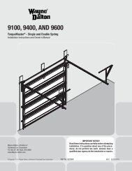
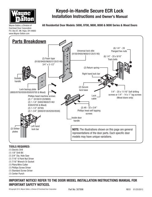
<strong>Keyed</strong>-<strong>in</strong>-<strong>Handle</strong> <strong>Secure</strong> <strong>ECR</strong> <strong>Lock</strong><br />
Installation Instructions and Owner’s Manual<br />
<strong>Wayne</strong>-<strong>Dalton</strong>, a Division of<br />
Overhead Door Corporation<br />
P.O. Box 67, Mt. Hope, OH 44660<br />
www.<strong>Wayne</strong>-<strong>Dalton</strong>.com<br />
All Residential Door Models: 5000, 9700, 9800, 8000 & 9000 Series & Wood Doors<br />
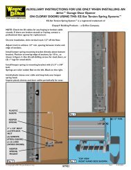
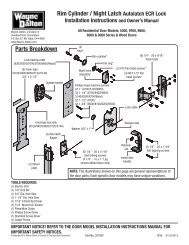
<strong>Parts</strong> <strong>Breakdown</strong><br />
Outside<br />
handle<br />
<strong>Lock</strong> backup plate<br />
(9800/9700/8300/8500/8700 & Wood)<br />
(2) Foam tape<br />
(9100/9400/9600/5120/5140)<br />
3/4” x 2-1/2”<br />
Phillips head mach<strong>in</strong>e screws<br />
(2) 1” (9100/5120/9800)<br />
(2) 1-1/4” (9400/9600/5140/<br />
8300/8700 & Wood)<br />
(2) 1-1/2” (9700)<br />
(2) 1-3/4” (8000/8100/8200/8500)<br />
Universal lock stile<br />
(9100/9400/9600/5120/5140)<br />
Inside door<br />
handle<br />
(2) <strong>Secure</strong><br />
lock base<br />
(2) Return spr<strong>in</strong>g<br />
Right hand lock bar<br />
<strong>Lock</strong><br />
cable<br />
(2) #8 - 32 x 3/4”<br />
Phillips head self tapp<strong>in</strong>g<br />
screws<br />
(6) 1/4” - 20<br />
Flanged hex nuts<br />
(6) 1/4” - 20 x 9/16”<br />
Track bolts<br />
1/4” - 20 x 11/16” Self drill<strong>in</strong>g<br />
screws or 1/4” - 14 x 1” lag screws<br />
(Wood doors only)<br />
(2) Striker<br />
plates<br />
Left hand<br />
lock bar<br />
NOTE: The illustrations shown on this page are general<br />
representations of the door parts. Each specific door<br />
models may have unique variations.<br />
TOOLS REQUIRED:<br />
(1) Electric Drill<br />
(1) 1/8” Drill Bit<br />
(1) 3/4” Dia. Hole Saw<br />
(1) 7/16” 6 Po<strong>in</strong>t Nut Driver<br />
(1) 7/16” Wrench Or Socket<br />
(1) Pliers/Wire Cutter<br />
(1) Phillips Screw Driver<br />
(1) Standard Screw Driver<br />
(1) Center Punch<br />
IMPORTANT NOTICE! REFER TO THE DOOR MODEL INSTALLATION INSTRUCTIONS MANUAL FOR<br />
IMPORTANT SAFETY NOTICES.<br />
©Copyright 2013, <strong>Wayne</strong>-<strong>Dalton</strong>, a Division Of Overhead Door Corporation<br />
Part No: 307896<br />
REV3 01/25/2013
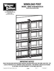
STEP 1: Drill<strong>in</strong>g <strong>Lock</strong> Section<br />
Center stile<br />
CAUTION<br />
DO NOT DRILL LOCK SECTION OR INSTALL LOCK ON<br />
DOORS WITH OPENERS. THE DOOR AND/ OR OPENER<br />
MAY BE DAMAGED IF THE OPENER IS USED WHILE THE<br />
DOOR IS LOCKED.<br />
NOTE: Common practice for doors with the odd number of raised<br />
panels is to mount the lock towards the right side of the section when<br />
look<strong>in</strong>g out.<br />
(3) Pre-punched<br />
holes<br />
(3) 3/4” Dia. holes<br />
IMPORTANT: REMOVE ALL BURRS FROM THE DRILLED HOLES BEFORE<br />
INSTALLING THE LOCK TO THE SECTION.<br />
8000/8100/8200 DOORS, (SEE FIG. 1): Place the lock section face<br />
down on (2) padded sawhorses for a s<strong>in</strong>gle car door or (3) padded<br />
sawhorses for a double car door. Locate the (3) hole pattern <strong>in</strong> the<br />
center stile of the lock section. Use the (3) holes as a template to drill<br />
(3) 1/8” diameter holes through the section. Flip the section over, face<br />
up. With the section face up, enlarge all (3) holes to 3/4” diameter,<br />
pay close attention NOT TO DRILL completely through section <strong>in</strong>to the<br />
center stile.<br />
NOTE: Do not drill through or enlarge holes <strong>in</strong> the center stile.<br />
7/16” dia. hole<br />
FACE DOWN<br />
FIG. 1<br />
FACE UP<br />
Vertical<br />
mark<br />
Horizontal mark<br />
9800/9700/8300/8500/8700 & WOOD DOORS, (SEE FIG. 2): Place<br />
the lock section face up on (2) padded sawhorses for a s<strong>in</strong>gle car door<br />
or (3) padded sawhorses for a double car door. Locate the middle of<br />
the center stile, measure the distance from the end of the section to<br />
the middle of the center stile. Turn the section face down, transfer the<br />
measurement and mark a light vertical l<strong>in</strong>e, then mark a horizontal<br />
l<strong>in</strong>e at half the section height. Align the 7/16” diameter hole of the lock<br />
backup plate at the <strong>in</strong>tersection po<strong>in</strong>t of the horizontal and vertical<br />
marks, use the lock backup plate as a template to mark the (3) holes,<br />
remove the lock backup plate and drill (3) 3/4” diameter holes through<br />
the section.<br />
<strong>Lock</strong> backup plate<br />
1/2 The section<br />
height<br />
FIG. 2<br />
(3) 3/4”dia.<br />
holes<br />
FACE DOWN<br />
5120/5140/9100/9400 & 9600 DOORS, (SEE FIG. 3): Place the lock<br />
section face up on (2) padded sawhorses for a s<strong>in</strong>gle car door or (3)<br />
padded sawhorses for a double car door. Locate the middle of the<br />
center stile, measure the distance from the end of the section to the<br />
middle of the center stile. Turn the section face down, transfer the<br />
measurement and mark a light vertical l<strong>in</strong>e. Align the center of the<br />
lock stile with vertical mark, use the lock stile as a template to mark<br />
the (3) holes, remove the lock stile and drill (3) 3/4” diameter holes<br />
through the section.<br />
<strong>Lock</strong><br />
stile<br />
(3) 3/4”<br />
Dia. Holes<br />
Vertical<br />
mark<br />
FACE DOWN<br />
FIG. 3<br />
2
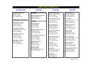
STEP 2: Outside <strong>Lock</strong> <strong>Handle</strong> Assembly<br />
8000/8100/8200 DOORS, (SEE FIG. 4): Align the outside handle<br />
assembly with the handle po<strong>in</strong>t<strong>in</strong>g towards the floor and <strong>in</strong>sert the<br />
assembly through the previously drilled 3/4” diameter holes <strong>in</strong> the<br />
section. <strong>Secure</strong> the outside lock handle to the section with (2) #10<br />
phillips head screws.<br />
Outside<br />
handle<br />
3/4” dia.<br />
holes<br />
Shank<br />
#10 Phillips<br />
head screws<br />
5120/5140/8300/8500/9700/9800/9100/9400/9600 & WOOD<br />
DOORS, (SEE FIG. 5A & FIG. 5B): Align the outside handle assembly<br />
with the handle po<strong>in</strong>t<strong>in</strong>g towards the floor and <strong>in</strong>sert the assembly<br />
through the previously drilled 3/4” diameter holes <strong>in</strong> the section. With<br />
the outside lock placed <strong>in</strong> the section, place the center lock stile over<br />
the shank of the outside lock handle, secure the center lock stile with<br />
foam tape (9700/8300/8500/8700 Series & Wood doors will use the<br />
lock backup plate with no foam tape). <strong>Secure</strong> the outside lock handle<br />
to the section by plac<strong>in</strong>g the (2) #10 phillips head mach<strong>in</strong>e screws<br />
through the lock stile <strong>in</strong>to the lock section.<br />
NOTE: Before proceed<strong>in</strong>g to the next step its recommended that the<br />
outside handle be locked.<br />
3/4” Dia.<br />
holes<br />
Outside<br />
handle<br />
FIG. 4<br />
Foam tape<br />
<strong>Handle</strong><br />
shank<br />
Foam tape<br />
Universal<br />
lock stile<br />
#10<br />
Phillips<br />
head<br />
screws<br />
STEP 3: Inside <strong>Handle</strong> Assembly<br />
FIG. 5A<br />
8000/8100/8200 DOORS, (SEE FIG. 6): Position the <strong>in</strong>side handle<br />
over the shank of the outside handle, flush aga<strong>in</strong>st the center stile.<br />
Align the holes <strong>in</strong> the handle with the pre-punched holes <strong>in</strong> the center<br />
stile, then turn the handle clockwise to secure with (2) #8 screws.<br />
5120/5140/8300/8500/9700/9800/9100/9400/9600 & WOOD<br />
DOORS (SEE FIG. 7): Position the <strong>in</strong>side handle over the shank of the<br />
outside handle, flush aga<strong>in</strong>st the lock backup plate. Align the holes <strong>in</strong><br />
the handle with the pre-punched holes <strong>in</strong> the lock backup plate, then<br />
turn the handle clockwise to secure with (2) #8 screws.<br />
NOTE: When secur<strong>in</strong>g the <strong>in</strong>side handle bracket, be sure not to over<br />
tighten the screws or damage to the <strong>in</strong>side handle may occur.<br />
3/4” Dia.<br />
holes<br />
Outside<br />
handle<br />
<strong>Lock</strong><br />
backup<br />
plate<br />
<strong>Handle</strong><br />
shank<br />
FIG. 5B<br />
Pre-punched holes<br />
Shank<br />
Inside<br />
handle<br />
#10<br />
Phillips<br />
head<br />
screws<br />
NOTE: Follow the Ma<strong>in</strong> Installation Instruction Manual to <strong>in</strong>stall the<br />
door sections and vertical track before you <strong>in</strong>stall the rema<strong>in</strong>der of<br />
the lock parts. After the sections and track are <strong>in</strong>stalled, cont<strong>in</strong>ue with<br />
STEP 4.<br />
Inside<br />
handle<br />
Center stile<br />
FIG. 6<br />
(2) #8<br />
Screws<br />
<strong>Lock</strong><br />
stile<br />
Inside<br />
handle<br />
Shank<br />
Backup plate<br />
Inside<br />
handle<br />
Shank<br />
Pre-punched<br />
holes<br />
(2) #8<br />
Screws<br />
Inside<br />
handle<br />
Pre-punched<br />
holes<br />
(2) #8<br />
Screws<br />
FIG. 7<br />
3
STEP 4: Install<strong>in</strong>g The <strong>Secure</strong> <strong>Lock</strong><br />
Locate the <strong>in</strong>side handle and uncoil the lock cable. Thread the lock<br />
cable through the <strong>in</strong>side handle, (SEE FIG. 8).<br />
Next, locate the secure lock striker plates over the pre-punched holes<br />
<strong>in</strong> the vertical track nearest the center of the lock section, (SEE FIG.<br />
9). Fasten the striker plates to the vertical track us<strong>in</strong>g (2) 1/4” - 20 x<br />
9/16” track bolts and flanged hex nuts. <strong>Lock</strong> bars are embossed “R”<br />
for right side and “L” for left side. Place the lock bars <strong>in</strong>to the slots <strong>in</strong><br />
the secure lock base. Attach the spr<strong>in</strong>gs to the tabs on the base and<br />
the lock bar. Position the end of the right lock bar <strong>in</strong>to the slot <strong>in</strong> the<br />
right striker plate. Move the base of the secure lock back 1/8” from<br />
the edge of the section. Attach the secure lock to the section with (4)<br />
1/4” - 20 x 11/16” self drill<strong>in</strong>g screws. Repeat for the left side. Feed<br />
one end of the lock cable through the slotted hole of a lock bar and<br />
secure with (1) 1/4” - 20 x 9/16” track bolt. Pull the cable taut, but not<br />
enough to pull the lock bar out of the striker plate. While hold<strong>in</strong>g taut,<br />
feed the lock cable through the slotted hole of the rema<strong>in</strong><strong>in</strong>g lock bar,<br />
secure with (1) 1/4” - 20 x 9/16” track bolt and flanged hex nut, (SEE<br />
FIG. 9-10).<br />
<strong>Lock</strong><br />
cable<br />
8a<br />
8b<br />
8d<br />
<strong>Lock</strong> cable<br />
Inside<br />
handle<br />
8c<br />
<strong>Lock</strong> cable<br />
Inside<br />
handle<br />
Inside<br />
handle<br />
Inside<br />
handle<br />
<strong>Lock</strong><br />
cable<br />
NOTE: Ensure that the bolt is through the front of the lock bar and the<br />
nut is on the back of the lock bar with cable go<strong>in</strong>g through the front of<br />
the lock bar.<br />
<strong>Lock</strong><br />
cable<br />
Operate the lock several times to make sure the lock bars clear the<br />
striker plates when the handle is turned and the lock bars engage<br />
the striker plates when the handle is released. Adjust the cables if<br />
necessary. Trim off the excess cable with wire cutters after the lock is<br />
operat<strong>in</strong>g satisfactorily.<br />
FIG. 8<br />
<strong>Secure</strong><br />
lock<br />
base<br />
Right<br />
hand<br />
lock<br />
bar<br />
1/8” Offset from<br />
edge of door<br />
<strong>Lock</strong><br />
cable<br />
1/4” - 20<br />
Flanged hex<br />
nuts<br />
Striker<br />
plate<br />
Vertical<br />
track<br />
1/4” - 20 x 11/16”<br />
Self drill screws<br />
1/4” - 20 x 9/16”<br />
Track bolts<br />
Left hand<br />
lock bar<br />
Inside<br />
handle<br />
Hook spr<strong>in</strong>g over tabs<br />
on lock bar and base<br />
9700 Series Doors<br />
use back slot<br />
Slide lock bar<br />
through the<br />
front slot<br />
FIG. 10<br />
Align lock bar<br />
<strong>in</strong>to front slot<br />
<strong>Lock</strong> bars are embossed for<br />
identification<br />
FIG. 9<br />
4