XLH260
XLH260
XLH260

You also want an ePaper? Increase the reach of your titles
YUMPU automatically turns print PDFs into web optimized ePapers that Google loves.
dIXEL<br />
Operating instructions<br />
cod. 1592017400<br />
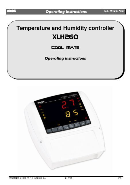
Temperature and Humidity controller<br />
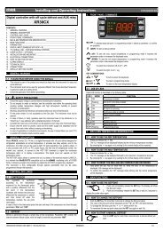
<strong>XLH260</strong><br />
COOL<br />
MATE<br />
Operating instructions<br />
1592017400 <strong>XLH260</strong> GB r1.0 15.04.2005.doc <strong>XLH260</strong> 1/15
dIXEL<br />
Operating instructions<br />
cod. 1592017400<br />
COOL<br />
OOLMATE<br />
<strong>XLH260</strong><br />
INDICE<br />
1. GENERAL WARNINGS_________________________________________________________ 3<br />
2. GENERAL DESCRIPTION ______________________________________________________ 3<br />
3. TEMPERATURE REGULATION __________________________________________________ 3<br />
4. HUMIDITY REGULATION_______________________________________________________ 3<br />
5. FA NS ______________________________________________________________________ 4<br />
6. THE DISPLAY ________________________________________________________________ 5<br />
7. PARAMETER LIST ____________________________________________________________ 7<br />
8. DIGITAL INPUT_______________________________________________________________ 9<br />
9. INSTALLATION AND MOUNTING _______________________________________________ 10<br />
10. DIMENSIONS _______________________________________________________________ 12<br />
11. ELECTRICAL CONNECTIONS__________________________________________________ 12<br />
12. HOW TO USE THE HOT KEY __________________________________________________ 12<br />
13. ALARM SIGNALLING _________________________________________________________ 13<br />
10. TECHNICAL DATA ___________________________________________________________ 13<br />
14. <strong>XLH260</strong> CONNECTIONS ______________________________________________________ 14<br />
15. DEFAULT SETTING VALUES __________________________________________________ 14<br />
1592017400 <strong>XLH260</strong> GB r1.0 15.04.2005.doc <strong>XLH260</strong> 2/15
dIXEL<br />
Operating instructions<br />
cod. 1592017400<br />
1. GENERAL WARNINGS<br />
1.1 PLEASE READ BEFORE USING THIS MANUAL<br />
• This manual is part of the product and should be kept near the instrument for easy and quick reference.<br />
• The instrument shall not be used for purposes different from those described hereunder. It cannot be used as a safety device.<br />
• Check the application limits before proceeding.<br />
1.2 SAFETY PRECAUTIONS<br />
• Check the supply voltage is correct before connecting the instrument.<br />
• Do not expose to water or moisture: use the controller only within the operating limits avoiding sudden temperature changes with high<br />
atmospheric humidity to prevent formation of condensation<br />
• Warning: disconnect all electrical connections before any kind of maintenance.<br />
• Fit the probe where it is not accessible by the End User. The instrument must not be opened.<br />
• In case of failure or faulty operation send the instrument back to the distributor or to “Dixell s.r.l.” (see address) with a detailed description of the<br />
fault.<br />
• Consider the maximum current which can be applied to each relay (see Technical Data).<br />
• Ensure that the wires for probes, loads and the power supply are separated and far enough from each other, without crossing or intertwining.<br />
• In case of applications in industrial environments, the use of mains filters (our mod. FT1) in parallel with inductive loads could be useful.<br />
2. GENERAL DESCRIPTION<br />
The <strong>XLH260</strong> is microprocessor controller, suitable for applications on medium or low temperature refrigerating units. It control both humidity and<br />
temperature. It has 6 output relays to control compressor, heating elements, defrost, fan de-humidifier and humidifier. It has 2 NTC inputs one for<br />
thermostat the other one for defrost. It’s also present an 4÷20mA input for humidity. There is one digital input (free contact) configurable by<br />
parameter. An output allows the user to program the parameter list with the “Hot Key”.<br />
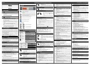
3. TEMPERATURE REGULATION<br />
The temperature regulation is performed through neutral zone using compressor and heater output relays.<br />
ON<br />
OFF<br />
Set point<br />
• Heating output: CUT IN is “SET TEMP- dbt”, CUT OUT is when the temperature reaches the set point.<br />
• Compressor output: CUT IN is “ SET TEMP + dbt”, CUT OUT is when the temperature reaches the set point.<br />
3.1 DEFROST<br />
Two defrost modes are available through the “tdF” parameter: defrost with electrical heater or hot gas. The defrost interval is controlled by means of<br />
parameter “EdF”: (EdF=in) the defrost is made every “IdF” time, (EdF=Sd) the interval “IdF” is calculate through Smart Defrost algorithm (only when<br />
the compressor is ON). To disable the defrost set the MdF parameter to zero<br />
Humidity regulation during a defrost depends on the Hud parameter. With Hud=no humidity regulation is disabled. With Hud=yES humidity<br />
regulation is performed also during a defrost.<br />
4. HUMIDITY REGULATION<br />
The humidity regulation is performed through neutral zone, by humidifying dehumidifying actions. Humidity control can be disabled setting the SET<br />
%RH to “nu” value. In this case only the temperature control is perform.<br />
4.1 HUMIDIFYING ACTION<br />
The humidifying action is done enabling the humidifier relay when the humidity is lower than the “SET %RH-dbH” value. The relay is switch off when<br />
humidity reaches the set values.<br />
4.2 DEHUMIDIFYING ACTION WITHOUT DEHUMIDIFIER RELAY (OA1 DIFFERENT FROM DEH) – STANDARD CONFIGURATION<br />
In this case the dehumidifying action is performed by setting the following parameters in this way:<br />
tHu = cH kind of dehumidifying by means of heating and compressor relays<br />
oA1 different from dEH:<br />
1592017400 <strong>XLH260</strong> GB r1.0 15.04.2005.doc <strong>XLH260</strong> 3/15
dIXEL<br />
Operating instructions<br />
cod. 1592017400<br />
The heating and compressor outputs are activated together when humidity is higher than SET %RH+dbH value. Outputs are disabled when humidity<br />
comes back to the SET %RH value.<br />
4.2.1 Relation between cooling, heating and dehumidifying<br />
1. If is simultaneously present a request of cooling (temp>SET TEMP+dbt) and dehumidifying (RH > SET %RH+dbH): the cooling action has the<br />
priority over the dehumidifying action: only the compressor relay is energised till the SET TEMP is reached at this point also the heating relay<br />
is enabled.<br />
2. If is simultaneously present a request of heating (temp< SET TEMP-dbt) and dehumidifying (RH > SET %RH+dbH): the dehumidifying action<br />
has the priority over the heating action: both the compressor and the heating relays are energised till the humidity set is reached at this point<br />
only the heating relay is enabled.<br />
4.3 DEHUMIDIFYING ACTION WITH DEHUMIDIFIER RELAY (OA1 = DEH)<br />
The configurable relay is used, setting the parameter oA1 =dEH.<br />
NOTE: the LIGHT button is not more available;<br />
Two kinds of de-humidifying are available:<br />
4.3.1 Dehumidifying action with ONLY de-humidifier relay<br />
By setting the parameter tHu = db the de-humidifying action is performed by enabling the de-humidifier relay when the humidity is higher than SET<br />
%RH + dbH.<br />
The relay is switch off when humidity comes back to the SET %RH value.<br />
4.3.2 Dehumidifying action with de-humidifier and compressor relays<br />
By setting the parameter tHu = cHu the de-humidifying action is performed by enabling the de-humidifier and compressor relays together. when the<br />
humidity is higher than SET %RH + dbH.<br />
The relays are switched off when humidity comes back to the SET %RH value.<br />
If is simultaneously present a request of cooling (temp>SET TEMP+dbt) and dehumidifying (RH > SET %RH+dbH): the cooling action has the priority<br />
over the dehumidifying action: only the compressor relay is energised till the SET TEMP is reached at this point also the de-humidifier is enabled.<br />
5. FA NS<br />
The fan control mode is selected by means of the “FnC” parameter:<br />
FnC=C-n fans will switch ON and OFF with the compressor and not run during defrost:;<br />
FnC= O-n fans will run continuously, but not during defrost<br />
FnC=C-y fans will switch ON and OFF with the compressor and run during defrost;<br />
FnC=O-y fans will run continuously also during defrost<br />
1592017400 <strong>XLH260</strong> GB r1.0 15.04.2005.doc <strong>XLH260</strong> 4/15
dIXEL<br />
Operating instructions<br />
cod. 1592017400<br />
6. THE DISPLAY<br />
C<br />
F<br />
%RH<br />
SET<br />
SET<br />
KEY COMBINATIONS<br />
To display and modify target temperature set point. (SET TEMP)<br />
To display and modify target humidity set point (SET %RH); in programming mode it selects a parameter or confirm an operation.<br />
In programming mode it browses the parameter codes or increases the displayed value.<br />
To start a manual defrost: hold it pressed for at least 3s.<br />
In programming mode it browses the parameter codes or decreases the displayed value.<br />
Switch ON and OFF the light, if present (oA1=lig)<br />
Switch ON and OFF the instrument.<br />
+ To lock and unlock the keyboard<br />
+ To enter the programming mode.<br />
+ To exit the programming mode.<br />
6.1 ICONS AND SYMBOLS<br />
Each LED function is described in the following table.<br />
LED MODE FUNCTION<br />
ON<br />
- Instrument in stand by.<br />
- In “Pr2” indicates that the parameter is also present in “Pr1”.<br />
°C ON °C<br />
°C FLASHING If measurement unit is °C, it flashing on programming mode<br />
°F ON °F<br />
°F FLASHING If measurement unit is °F, it flashing on programming mode<br />
1592017400 <strong>XLH260</strong> GB r1.0 15.04.2005.doc <strong>XLH260</strong> 5/15
dIXEL<br />
LED MODE FUNCTION<br />
ON The compressor is running<br />
Operating instructions<br />
cod. 1592017400<br />
(temp)<br />
(umid)<br />
FLASHING<br />
ON<br />
FLASHING<br />
ON<br />
FLASHING<br />
ON<br />
ON<br />
ON<br />
ON<br />
ON<br />
ON<br />
FLASHING<br />
Anti-short cycle delay enabled<br />
The defrost is enabled<br />
Drip time in progress<br />
Heating enabled<br />
Temperature Set programming phase<br />
ALARM signal<br />
Fan is running<br />
The light is on<br />
RH%<br />
Dehumidifying enabled<br />
Humidifying enabled<br />
Humidity Set programming phase<br />
6.2 HOW TO SEE AND MODIFY THE SET POINT (TEMPERATURE AND HUMIDITY)<br />
OR<br />
1. Push and immediately release the SET key: the display will show the Set point value and the correspondent set icon starts<br />
flashing;<br />
2. To change the Set value push the o or n arrows within 10s.<br />
3. To memorise the new set point value push the SET key again or wait 10s.<br />
6.3 TO START A MANUAL DEFROST<br />
1. Push the DOWN key for more than 2 seconds and a manual defrost will start.<br />
6.4 TO ENTER IN PARAMETERS LIST “PR1”<br />
To enter the parameter list “Pr1” (user accessible parameters) operate as follows:<br />
1. Enter the Programming mode by pressing the SET %RH+ n for few seconds. (°C or °F icon start flashing)<br />
+<br />
2. The instrument will show the first parameter present in “Pr1”<br />
6.5 TO ENTER IN PARAMETERS LIST “PR2”<br />
To access parameters in “Pr2”:<br />
1. Enter the “Pr1” level.<br />
2. Select “Pr2” parameter and press the “ SET %RH ” key.<br />
3. The “PAS” flashing message is displayed, shortly followed by “0 - -” with a flashing zero.<br />
4. Use o or n to input the security code in the flashing digit; confirm the figure by pressing “ SET %RH ”.<br />
The security code is “321“.<br />
5. If the security code is correct the access to “Pr2” is enabled by pressing “ SET %RH ” on the last digit.<br />
Another possibility is the following: after switching ON the instrument the user can push SET %RH + n keys within 30 seconds.<br />
NOTE: each parameter in “Pr2” can be removed or put into “Pr1” (user level) by pressing SET %RH + n. When a parameter is present in “Pr1”<br />
icon is on.<br />
6.6 TO CHANGE PARAMETER VALUES<br />
1. Enter the Programming mode.<br />
2. Select the required parameter with o or n.<br />
3. Press the “ SET %RH ” key to display its value (°C or °F icon start blinking).<br />
4. Use o or n to change its value.<br />
5. Press “ SET %RH ” to store the new value and move to the following parameter.<br />
To exit: Press SET %RH + UP or wait 15s without pressing a key.<br />
1592017400 <strong>XLH260</strong> GB r1.0 15.04.2005.doc <strong>XLH260</strong> 6/15
dIXEL<br />
Operating instructions<br />
NOTE: the new programming is stored even when the procedure is exited by waiting the time-out.<br />
6.7 HOW TO LOCK THE KEYBOARD<br />
cod. 1592017400<br />
AND<br />
1. Keep the o and n keys pressed together for more than 3 s the o and n keys.<br />
2. The “POF” message will be displayed and the keyboard is locked. At this point it is only possible the viewing of the set point or the<br />
MAX o Min temperature stored and to switch ON and OFF the light, the auxiliary output and the instrument.<br />
TO UNLOCK THE KEYBOARD<br />
Keep the o and n keys pressed together for more than 3s.<br />
6.8 ON/OFF FUNCTION<br />
By pushing the ON/OFF key, the instrument shows “OFF” for 5 sec. and the ON/OFF LED is switched ON.<br />
During the OFF status, all the relays are switched OFF and the regulations are stopped;<br />
N.B. During the OFF status the icon is lighted.<br />
7. PARAMETER LIST<br />
REGULATION<br />
dbt half dead band width for temperature: (0,1÷25,5°C; 1÷45°F) this band is place below and above the temperature set point (SET TEMP).<br />
The compressor is enabled when the temperature increases and reaches the SET TEMP + dbt value. It is turned off when it comes back to<br />
the SET TEMP. The heating output is enabled when temperature is less than SET TEMP -dbt value and disabled when the SET TEMP is<br />
reached.<br />
dbH half dead band width for humidity: (0,5÷25,5RH) this band is place below and above the humidity set point (SET %RH). The<br />
dehumidifying action is enabled when the humidity increases and reaches the SET %RH + dbH value. It is stopped when it comes back to<br />
the SET %RH. The humidifying output is enabled when humidity is less than SET %RH -dbH value and disabled when the SET %RH is<br />
reached.<br />
LS Minimum temperature set point limit: (-50,0°C÷SET; -58°F÷SET) Sets the minimum acceptable value for the set point.<br />
US Maximum temperature set point limit: (SET÷110°C; SET÷230°F) Set the maximum acceptable value for set point.<br />
OdS Outputs activation delay at start up: (0÷255 min) This function is enabled at the initial start up of the instrument and inhibits any output<br />
activation for the period of time set in the parameter. (Light can work)<br />
AC Anti-short cycle delay: (0÷30 min) interval between the compressor stop and the following restart.<br />
tHu Kind of de-humidifying: db: only with de-humidifier relay (oA1= dEH); cHu with de-humidifier and compressor relay (oA1= dEH); c-H:<br />
without de-humidifier relay, by means of compressor and heating relays (oA1≠ dEH).<br />
LSH Minimum humidity set point limit: (Lci ÷ Set H) Sets the minimum acceptable value for the humidity set point.<br />
USH Maximum humidity set point limit: (Set H ÷ uci) Set the maximum acceptable value for humidity set point.<br />
DISPLAY<br />
CF Measurement unit: °C= Celsius; °F= Fahrenheit<br />
rES Resolution (for °C): allows decimal point display. dE = 0,1°C; in = 1 °C<br />
rEH Resolution for RH%: in = integer; Hd= half digit.<br />
DEFROST<br />
tdF Defrost type: rE = electrical heater (Compressor OFF); in = hot gas (Compressor and defrost relays ON)<br />
EdF Defrost mode: in = interval mode. The defrost starts when the time “Idf” is expired. Sd =Smartfrost mode. The time IdF (interval<br />
between defrosts) is increased only when the compressor is running (even non consecutively).<br />
SdF Set point for SMARTFROST: (-30÷30 °C/ -22÷86 °F) evaporator temperature which allows the IdF counting (interval between defrosts) in<br />
SMARTFROST mode.<br />
dtE Defrost termination temperature: (-50,0÷110,0°C; -58÷230°F) (Enabled only when the evaporator probe is present) sets the temperature<br />
measured by the evaporator probe which causes the end of defrost.<br />
IdF Interval between defrosts: (1÷120h) Determines the time interval between the beginning of two defrost cycles.<br />
MdF Duration of defrost: (0÷255 min) When P2P = n, no evaporator probe, it sets the defrost duration, when P2P = y, defrost end based on<br />
temperature, it sets the maximum length for defrost.<br />
dFd Display during defrost: rt = real temperature; it = temperature reading at the defrost start; Set = set point; dEF = “dEF” label; dEG =<br />
“dEG” label;<br />
dAd Defrost display time out: (0÷255 min) Sets the maximum time between the end of defrost and the restarting of the real room temperature<br />
display.<br />
Fdt Drain down time: (0÷60 min.) time interval between reaching defrost termination temperature and the restoring of the control’s normal<br />
operation. This time allows the evaporator to eliminate water drops that might have formed due to defrost.<br />
dPO First defrost after start-up: y = Immediately; n = after the IdF time<br />
Hud Humidity control during defrost: no: the humidity control is stopped during the defrost; yES the humidity control works also during the<br />
defrost.<br />
FANS<br />
1592017400 <strong>XLH260</strong> GB r1.0 15.04.2005.doc <strong>XLH260</strong> 7/15
dIXEL<br />
Operating instructions<br />
cod. 1592017400<br />
FnC Fan operating mode: C-n = running when a load is on, OFF during the defrost; C-y = running when a load is on, ON during the defrost; O-n<br />
= continuous mode, OFF during the defrost; O-y = continuous mode, ON during the defrost;<br />
TEMPERATURE ALARMS<br />
ALC Temperature alarm configuration: rE = High and Low alarms related to Set Point; Ab = High and low alarms related to the absolute<br />
temperature.<br />
ALL Low temperature alarm setting: ALC = rE , 0 ÷ 50 °C or 90°F<br />
ALC = Ab , - 50°C or -58°F ÷ ALU<br />
when this temperature is reached and after the ALd delay time, the LA alarm is enabled,.<br />
ALU High temperature alarm setting: ALC= rE, 0 ÷ 50°C or 90°F<br />
ALC= Ab, ALL ÷ 110°C or 230°F<br />
when this temperature is reached and after the ALd delay time the HA alarm is enabled.<br />
ALH Temperature alarm recovery differential: (0,1÷25,5°C; 1÷45°F) Intervention differential for recovery of temperature alarm.<br />
ALd Temperature alarm delay: (0÷255 min) time interval between the detection of an alarm condition and the corresponding alarm signalling.<br />
dAO Delay of temperature alarm at start-up: (0min÷23h 50min) time interval between the detection of the temperature alarm condition after the<br />
instrument power on and the alarm signalling.<br />
EdA Alarm delay at the end of defrost: (0÷255 min) Time interval between the detection of the temperature alarm condition at the end of defrost<br />
and the alarm signalling.<br />
dot Delay of temperature alarm after closing the door : (0÷255 min) Time delay to signal the temperature alarm condition after closing the<br />
door.<br />
HUMIDITY ALARMS<br />
AHC Humidity alarm configuration: rE = High and Low alarms related to humidity Set Point; Ab = High and low alarms related to the “absolute”<br />
humidity.<br />
AHL Low humidity alarm setting: (with AHC = rE: 0 ÷ 50. With AHC = Ab: Lci ÷ AHu)<br />
when this humidity is reached and after the AHd delay time, the HLA alarm is enabled,.<br />
AHu High humidity alarm setting: (with AHC = rE: 0÷50°C. with AHC = Ab: AHL ÷ uci<br />
when this humidity is reached and after the AHd delay time the HHA alarm is enabled.<br />
AHH Humidity alarm recovery differential: (0.5÷20.0) Intervention differential for recovery of humidity alarm.<br />
AHd Humidity alarm delay: (0÷255 min) time interval between the detection of an alarm condition and the corresponding alarm signalling.<br />
dHo Delay of humidity alarm at start-up: (0min÷23h 50min) time interval between the detection of the humidity alarm condition after the<br />
instrument power on and the alarm signalling.<br />
doH Alarm delay at the end of defrost: (0÷255 min) Time interval between the detection of the humidity alarm condition at the end of defrost<br />
and the alarm signalling.<br />
doA Open door alarm delay:(0÷255 min) delay between the detection of the open door condition and its alarm signalling: the flashing message<br />
“dA” is displayed.<br />
nPS Pressure switch number: (0 ÷15) Number of activation of the pressure switch, during the “did” interval, before signalling the alarm event<br />
(I2F= PAL). If the nPS activation in the “did” time is reached, switch off and on the instrument to restart normal regulation.<br />
PROBE INPUTS<br />
Ot Thermostat probe calibration: (-12.0÷12.0°C/ -21÷21°F) allows to adjust possible offset of the thermostat probe.<br />
OE Evaporator probe calibration: (-12.0÷12.0°C/ -21÷21°F) allows to adjust possible offsets of the evaporator probe.<br />
O3 Humidity probe calibration: (-10÷10 RH) allows to adjust possible offsets of the humidity probe.<br />
P2P Evaporator probe presence: n= not present: the defrost stops only by time; y= present: the defrost stops by temperature and time.<br />
P3P Humidity probe presence: n= not present; y= present.<br />
LCI Readout with 4 mA : (-999 ÷ 999). Adjustment of read out corresponding to 4mA signal.<br />
UCI Readout with 20 mA : (-999 ÷ 999). Adjustment of read out corresponding to 20mA signal.<br />
DIGITAL INPUTS<br />
i1P Configurable digital input polarity: CL : the digital input is activated by closing the contact; OP : the digital input is activated by opening<br />
the contact;<br />
i2P Door switch digital input polarity: CL : the digital input is activated by closing the contact; OP : the digital input is activated by opening the<br />
contact;<br />
i1F Digital input operating mode: configure the digital input function: EAL = generic alarm; bAL = serious alarm mode; PAL = Pressure<br />
switch; Ht = heating relay safety; dor = door switch<br />
odc Outputs status when open door: on = normal; Fan = Fan OFF; oFF = all the loads off<br />
rrd Outputs restarting after doA alarm: no = outputs not affected by the doA alarm; yES = outputs restart with the doA alarm;<br />
did Time interval/delay for digital input alarm:(0÷255 min.) Time interval to calculate the number of the pressure switch activation when<br />
I1F=PAL. If I1F=EAL or bAL (external alarms), “did” parameter defines the time delay between the detection and the successive signalling of<br />
alarms.<br />
OTHER<br />
oA1 Light relay configuration: ALr = alarm; dEH = dehumidifier; onF = on/off relay: close with instrument on, open with instrument off; Lig =<br />
light, ESt, dEF not select<br />
1592017400 <strong>XLH260</strong> GB r1.0 15.04.2005.doc <strong>XLH260</strong> 8/15
dIXEL<br />
Adt<br />
AdH<br />
Ptb<br />
rEL<br />
Prd<br />
Pr2<br />
Operating instructions<br />
cod. 1592017400<br />
RS485 serial address, temperature section (0÷247) it identifies the temperature section of the instrument within a control or supervising<br />
system.<br />
NOTE: XJ500: set Adt different from AdH. X-WEB300/3000: set Adt equal to AdH.<br />
RS485 serial address, humidity section (0÷247) it identifies the humidity section of the instrument within a control or supervising system.<br />
Parameter table: (read only) it shows the original code of the dIXEL parameter map.<br />
Software release: (read only) Software version of the microprocessor.<br />
Probes display: (read only) display the temperature values of the evaporator probe Pb2.<br />
Access to the protected parameter list (read only).<br />
8. DIGITAL INPUT<br />
One digital input is present configurable by user by means of the i1F parameter according to the following descriptions.<br />
8.1 DIGITAL INPUT 1 (5-6): DOOR SWITCH<br />
It signals the door status and the corresponding relay output status through the “odc” parameter: no = normal (any change); Fan = Fan OFF; oFF =<br />
all the loads are switched off.<br />
Since the door is opened, after the delay time set through parameter “dOA”, the alarm output is enabled and the display shows the message “dA”.<br />
The status of loads depends on the “rrd” parameter:<br />
with rrd=no outputs are not affected by the doA alarm;<br />
with rrd=yES = outputs restart with the doA alarm;<br />
The alarm stops as soon as the external digital input is disabled again. During this time and then for the delay “dot” and “doH” after closing the door,<br />
the temperature and humidity alarms are disabled.<br />
8.2 DIGITAL INPUT 2 (3-4): GENERIC ALARM (I1F = EAL)<br />
As soon as the digital input is activated the unit will wait for “did” time delay before signalling the “EAL” alarm message. The outputs status don’t<br />
change. The alarm stops just after the digital input is de-activated.<br />
8.3 DIGITAL INPUT 2 (3-4): SERIOUS ALARM MODE (I1F = BAL)<br />
When the digital input is activated, the unit will wait for “did” delay before signalling the “bAL” alarm message. The relay outputs are switched OFF.<br />
The alarm will stop as soon as the digital input is de-activated.<br />
8.4 DIGITAL INPUT 2 (3-4): PRESSURE SWITCH (I1F = PAL)<br />
If during the interval time set by “did” parameter, the pressure switch has reached the number of activation of the “nPS” parameter, the “PAL”<br />
pressure alarm message will be displayed. The compressor and the regulation are stopped. When the digital input is ON the compressor is always<br />
OFF. If the nPS activation in the did time is reached, switch off and on the instrument to restart normal regulation.<br />
8.5 DIGITAL INPUT 2 (3-4): HEATING RELAY SAFETY (i1F=Ht)<br />
With i1F=Ht as soon as the digital input is activated for “did” time heating relay is disabled. The alarm will stop as soon as the digital input is deactivated.<br />
8.6 DIGITAL INPUTS POLARITY<br />
The digital input polarity depends on the “i1P” and “i2P”parameters. CL : the digital input is activated by closing the contact. OP : the digital input is<br />
activated by opening the contact<br />
1592017400 <strong>XLH260</strong> GB r1.0 15.04.2005.doc <strong>XLH260</strong> 9/15
dIXEL<br />
Operating instructions<br />
cod. 1592017400<br />
9. INSTALLATION AND MOUNTING<br />
The temperature range allowed for correct operation is 0 - 60 °C. Avoid places subject to strong vibrations, corrosive gases, excessive dirt or<br />
humidity. The same recommendations apply to probes. Let the air circulate by the cooling holes. Thanks to the case, <strong>XLH260</strong> model can be panel or<br />
wall mounted. See the following instructions for details.<br />
F<br />
G<br />
F<br />
G<br />
D<br />
E<br />
C<br />
B<br />
D<br />
A<br />
C<br />
B<br />
A<br />
FIG. 1<br />
FIG. 2<br />
87 230<br />
H<br />
130<br />
I<br />
MAX<br />
28<br />
MAX 37<br />
120<br />
210<br />
FIG. 3<br />
1592017400 <strong>XLH260</strong> GB r1.0 15.04.2005.doc <strong>XLH260</strong> 10/15
dIXEL<br />
Operating instructions<br />
cod. 1592017400<br />
A<br />
0<br />
200<br />
61<br />
106.44°<br />
0 18<br />
172<br />
190<br />
Fig. 6<br />
Fig. 4<br />
0<br />
6<br />
12<br />
61<br />
200<br />
192.5<br />
185<br />
R 5<br />
8.5<br />
106.44°<br />
8.5<br />
R 5<br />
0<br />
190<br />
4<br />
186<br />
11<br />
179<br />
14.5<br />
175.5<br />
22.5<br />
167.5<br />
29.5 160.55<br />
Fig. 5<br />
9.1 WALL MOUNTING<br />
1. Unscrew the 4 frontal screws (Fig. 1, A, B, F, G) and remove the cover (Fig. 1, C).<br />
2. Unscrew the 2 screws (Fig. 1, D, E) that keep connected the frontal and lower parts of Cool Mate and separate the 2 parts.<br />
3. Make the proper holes for cablepresses or pipepresses using the centres signed in the bottom cover of the Cool Mate, (Fig. 3, H, I, ). Then<br />
make 3 holes in the wall, as indicated in (Fig. 3, L, M, N), to fix the Cool Mate<br />
4. Fix the cablepresses and the pipepresses..<br />
5. Insert the wall-nugs, contained in the kit, into the holes made in the wall. Then use the o-rings and fix the back part of the Cool Mate (Fig. 3, L,<br />
M, N) by means of the 3 screws to the wall itself.<br />
6. Insert the wiring cables in cablepresses or in the pipepresses.<br />
7. Mount the frontal part using the previous 4 screws Fig. 1, D, E, F, G. (do not press excessively in order to avoid plastic deformation).<br />
8. After connecting the wires to the terminal blocks close the cover (Fig. 2, c) and fix it by the screws.<br />
9.2 PANEL MOUNTING<br />
1. Make a hole in the panel with dimensions described in Fig. 4 (simplified) or Fig. 5 (completed)<br />
2. Unscrew the 4 frontal screws (Fig. 1, A, B, F, G) and remove the cover (Fig. 1, C).<br />
1592017400 <strong>XLH260</strong> GB r1.0 15.04.2005.doc <strong>XLH260</strong> 11/15
dIXEL<br />
Operating instructions<br />
cod. 1592017400<br />
3. Unscrew the 2 screws (Fig. 1, D, E) that keep connected the frontal and lower parts of Cool Mate and separate the 2 parts.<br />
4. Cut from the back part of the Cool Mate the teeth indicated in Fig. 6, A.<br />
5. Make the proper holes for cablepresses or pipepresses using the centres signed in the bottom cover of the Cool Mate, (Fig. 3, H, I, ).<br />
6. Fix the cablepresses and the pipepresses..<br />
7. Insert the wiring cables in cablepresses or in the pipepresses.<br />
8. Join the back and frontal parts, with the panel in the middle, and fix them screwing the 4 screws taken previously away (dimensions 4x35<br />
mm), in the holes of Fig. 1, A, B, D, E. Maximum panel thickness: 6mm.<br />
9. After connecting the wires to the terminal blocks close the cover (Fig. 2, c) and fix it by the screws.<br />
10. DIMENSIONS<br />
210 87<br />
230<br />
11. ELECTRICAL CONNECTIONS<br />
The instruments are provided with screw terminal block to connect cables with a cross section up to 2,5 mm 2 . Heat-resistant cables have to be used.<br />
Before connecting cables make sure the power supply complies with the instrument’s requirements. Separate the probe cables from the power<br />
supply cables, from the outputs and the power connections. Do not exceed the maximum current allowed on each relay, in case of heavier loads use<br />
a suitable external relay.<br />
11.1 PROBE CONNECTIONS<br />
The probes shall be mounted with the bulb upwards to prevent damages due to casual liquid infiltration. It is recommended to place the thermostat<br />
probe away from air streams to correctly measure the average room temperature.<br />
12. HOW TO USE THE HOT KEY<br />
12.1 HOW TO PROGRAM A HOT KEY FROM THE INSTRUMENT (UPLOAD)<br />
1. Program one controller with the front keypad.<br />
2. When the controller is ON, insert the “Hot key” and push o key; the "uPL" message appears followed a by flashing “End”<br />
3. Push “SET” key and the End will stop flashing.<br />
4. Turn OFF the instrument remove the “Hot Key”, then turn it ON again.<br />
NOTE: the “Err” message is displayed for failed programming. In this case push again o key if you want to restart the upload again or remove the<br />
“Hot key” to abort the operation.<br />
12.2 HOW TO PROGRAM AN INSTRUMENT USING A HOT KEY (DOWNLOAD)<br />
1. Turn OFF the instrument.<br />
2. Insert a programmed “Hot Key” into the 5 PIN receptacle and then turn the Controller ON.<br />
3. Automatically the parameter list of the “Hot Key” is downloaded into the Controller memory, the “doL” message is blinking followed a by<br />
flashing “End”.<br />
4. After 10 seconds the instrument will restart working with the new parameters.<br />
5. Remove the “Hot Key”..<br />
NOTE the message “Err” is displayed for failed programming. In this case turn the unit off and then on if you want to restart the download again or<br />
remove the “Hot key” to abort the operation.<br />
1592017400 <strong>XLH260</strong> GB r1.0 15.04.2005.doc <strong>XLH260</strong> 12/15
dIXEL<br />
13. ALARM SIGNALLING<br />
Operating instructions<br />
cod. 1592017400<br />
Message Cause<br />
Outputs<br />
“P1” Thermostat probe failure Compressor and heating outputs off<br />
“P2” Evaporator probe failure Defrost and by time<br />
“P3” Humidity probe failure Humidity regulation off<br />
“HA” High temperature alarm Outputs unchanged<br />
“LA” Low temperature alarm Outputs unchanged<br />
“HHA” High humidity alarm Outputs unchanged<br />
“HLA” Low humidity alarm Outputs unchanged<br />
“dA” Door switch alarm Outputs depending on the odC parameter<br />
“EAL” External alarm Other outputs unchanged<br />
“BAL” Serious external alarm Outputs OFF<br />
“PAL” Pressure switch alarm Outputs OFF<br />
The alarm message is displayed until the alarm condition recoveries.<br />
All the alarm messages are showed alternating with the room temperature except for the “P1” which is flashing. To reset the “EE” alarm and restart<br />
the normal functioning press any key, the “rSt” message is displayed for about 3s.<br />
13.1 SILENCING BUZZER<br />
Once the alarm signal is detected the buzzer, if present, can be silenced by pressing any key.<br />
13.2 ALARM RECOVERY<br />
Probe alarms : “P1” (probe1 faulty), “P2”, “P3”; they automatically stop 10s after the probe restarts normal operation. Check connections before<br />
replacing the probe.<br />
Temperature alarms “HA” and “LA” automatically stop as soon as the thermostat temperature returns to normal values or when the defrost starts.<br />
Humidity alarms “HHA” and “LHA” automatically stop as soon as the humidity returns to normal values.<br />
Door switch alarm “dA” stop as soon as the door is closed.<br />
External alarms “EAL”, “BAL” stop as soon as the external digital input is disabled<br />
Pressure switch alarm “PAL” alarm is recovered by switching OFF the instrument.<br />
10. TECHNICAL DATA<br />
Housing: self extinguishing ABS; Case: frontal 210x230 mm; depth 87mm; Mounting: See par. 9; Protection: IP65<br />
Connections: Screw terminal block ≤ 2,5 mm 2 wiring.<br />
Power supply: 230Vac 50/60Hz ± 10% or 110Vac 50/60Hz ± 10%; Power absorption: 10VA max.<br />
Display:3 digits, red LED, 30.5 mm high; 3 digits, yellow LED low.<br />
Inputs: 2 NTC probes, one 4÷20mA input<br />
Digital inputs : door switch and configurable, free voltage. Max. distance 10m<br />
Relay outputs:<br />
compressor: relay SPST 20(8) A, 250Vac;<br />
defrost: relay SPDT 16(3) A, 250Vac;<br />
fans: relay SPST 8(3) A, 250Vac;<br />
heater control: relay SPST 20(8) A, 250Vac;<br />
Humidifying: relay SPST 8(3) A, 250Vac;<br />
Dehumidifying / Light: relay SPST 16(3) A, 250Vac<br />
Other output :<br />
Alarm buzzer (Standard)<br />
Direct RS485 (optional)<br />
Data storing: on the non-volatile memory (EEPROM).<br />
Kind of action: 1B.; Pollution grade: normal; Software class: A.<br />
Operating temperature: 0÷60 °C.; Storage temperature: -25÷60 °C.<br />
Relative humidity: 20÷85% (no condensing)<br />
Measuring and regulation range: NTC probe: -40÷110°C (-58÷230°F);<br />
Resolution: 0,1 °C or 1°C or 1 °F (selectable).<br />
Accuracy (ambient temp. 25°C): ±0,5 °C ±1 digit<br />
1592017400 <strong>XLH260</strong> GB r1.0 15.04.2005.doc <strong>XLH260</strong> 13/15
dIXEL<br />
14. <strong>XLH260</strong> CONNECTIONS<br />
Operating instructions<br />
cod. 1592017400<br />
HO T KEY<br />
35 36<br />
RS 485<br />
(optionaal)<br />
20A 250V<br />
16 FLA (96L RA)<br />
20A 250V<br />
16FLA(96L RA)<br />
16A<br />
250V~ 250V~ 16A<br />
250V~<br />
8A<br />
8A<br />
250V~<br />
1 2 3 4 5 6 7 8 9 101 1 12 13 14 151 6 17 18 19 20 21 222 3 24 25 26 2728 29 30 31 33 34<br />
Conf.<br />
In<br />
12V§ gnd<br />
Input<br />
Do or 4÷20mA<br />
15. DEFAULT SETTING VALUES<br />
Evap.<br />
Room<br />
Hea ter Comp<br />
L ight<br />
De-<br />
Hum Hum<br />
NC Line N<br />
Supply<br />
Fa n 120/230V~<br />
Label Value Menu Description Range<br />
Set T 5.0 - - - Temperature Set Point LS ÷ uS ( nu = temperature regulation disabled )<br />
Set H 50.0 - - - Humidity Set Point LSH ÷ uSH ( nu = humidity regulation disabled)<br />
dbt 2.0 Pr1 Half dead band width for temperature 0.1°C o 1°F ÷ 25°C o 77°F<br />
dbH 5.0 Pr1 Half dead band width for humidity 0.5 ÷ 50<br />
LS -40 Pr2 Minimum temperature set point limit -50.0°C o –58°F ÷ Set T<br />
uS 110 Pr2 Maximum temperature set point limit Set T ÷ 110°C o 230°F<br />
odS 1 Pr2 Outputs activation delay at start up 0 ÷ 250 min<br />
Ac 1 Pr1 Anti-short cycle delay 0 ÷ 30 min<br />
tHu c-H Pr2 Humidity regulation<br />
db = dehumidifier relay.; cHu = dehum+ compr.; c-H= without<br />
dehum. relay<br />
LSH 0.0 Pr2 Minimum humidity set point limit Lci ÷ Set H<br />
uSH 100.0 Pr2 Maximum humidity set point limit Set H ÷ uci<br />
cF °C Pr2 Measurement unit °C ÷°F<br />
rES dE Pr2 Resolution (for °C): in = integer / dE = decimal<br />
rEH Hd Pr2 Resolution for RH%: in = integer / Hd = half digit<br />
tdf rE Pr2 Defrost type rE, rT, in<br />
EdF in Pr2 Defrost mode In, Sd<br />
SdF 0 Pr2 Set point for SMART DEFROST -30 ÷ +30°C / -22÷+86°F<br />
dtE 8 Pr2 Defrost termination temperature -50,0÷110°C/ -58÷230°F<br />
idF 6 Pr1 Interval between defrosts 1 ÷ 120 h<br />
MdF 20 Pr1 Duration of defrost 0 ÷ 250 min<br />
dFd it Pr2 Display during defrost rt / it / SEt / dEF / dEG<br />
dAd 30 Pr2 Defrost display time out 0 ÷ 250 min<br />
Fdt 0 Pr2 Draining time 0÷60 min.<br />
dPo no Pr2 First defrost after start up n ÷ y<br />
Hud no Pr2 Humidity control during defrost no; yES<br />
Fnc c-n Pr2 Fan operating mode c-n / c-Y / o-n / o-Y<br />
ALc Ab Pr2 Temperature alarm configuration rE = relative / Ab = absolute<br />
ALL -40.0 Pr1 Low temperature alarm setting 0°C ÷ 50.0°C / -50.0°C ÷ ALu<br />
ALu 110 Pr1 High temperature alarm setting 0°C ÷ 50.0°C / ALL ÷ 110°C<br />
ALH 1.0 Pr2 Temperature alarm recovery differential 0.1°C o 1°F ÷ 25°C o 77°F<br />
ALd 15 Pr2 Temperature alarm delay 0 ÷ 250 min<br />
dAo 1.3 Pr2 Delay of temperature alarm at start-up 0.0 ÷ 23.5 h<br />
EdA 20 Pr2 Alarm delay at the end of defrost 0 ÷ 250 min<br />
dot 20 Pr2<br />
Delay of temperature alarm after closing the<br />
door<br />
0 ÷ 250 min<br />
AHc Ab Pr2 Humidity alarm configuration rE = relative / Ab = absolute<br />
AHL 0.0 Pr1 Low humidity alarm setting 0 ÷ 50 / Lci ÷ AHu<br />
AHu 100 Pr1 High humidity alarm setting 0 ÷ 50 / AHL ÷ uci<br />
AHH 2.0 Pr2 Humidity alarm recovery differential 0.5 ÷ 25<br />
AHd 15 Pr2 Humidity alarm delay 0 ÷ 250 min<br />
dHo 1.3 Pr2 Delay of humidity alarm at start-up 0.0 ÷ 23.5 h<br />
doH 20 Pr2 Alarm delay at the end of defrost 0 ÷ 250 min<br />
nPS 20 Pr2 Pressure switch number 0÷15<br />
1592017400 <strong>XLH260</strong> GB r1.0 15.04.2005.doc <strong>XLH260</strong> 14/15<br />
NC<br />
Def
dIXEL<br />
Operating instructions<br />
cod. 1592017400<br />
doA 0 Pr2 Open door alarm delay 0 ÷ 250 min ( 250 = nu )<br />
ot 0.0 Pr1 Thermostat probe calibration -12.0 ÷ 12.0<br />
oE 0.0 Pr2 Evaporator probe calibration -12.0 ÷ 12.0<br />
o3 0.0 Pr1 Humidity probe calibration -10 ÷ 10<br />
P2P YES Pr2 Evaporator probe presence no = absent / YES = present<br />
P3P YES Pr2 Humidity probe presence no = absent / YES = present<br />
Lci 0 Pr2 Readout with 4 mA -999 ÷ 999<br />
uci 100 Pr2 Readout with 20 mA -999 ÷ 999<br />
i1P cL Pr2 Configurable digital input polarity cL =open / oP = close<br />
i2P cL Pr2 Door switch digital input polarity cL =open / oP = close<br />
i1F EAL Pr2 Digital input configuration dor / PAL / EAL / bAL / Ht<br />
odc FAn Pr2 Outputs status when open door on / Fan / oFF<br />
rrd YES Pr2 Outputs restarting after doA alarm no = no / YES = yes<br />
did 5 Pr2 Digital input alarm delay 0÷255 min.<br />
oA1 Lig Pr2 Light relay configuration:<br />
ALr = alarm; dEH = dehumidifier; onF = on/off; Lig = light,<br />
ESt, dEF not select<br />
Adr 1 Pr2 Serial address 0÷247 num<br />
Ptb - Pr2 Parameter table - - -<br />
rEL 1.0 Pr2 Software release - - -<br />
Prd -- Pr2 Probes display Pb1÷Pb3<br />
Pr2 321 Pr1 Access to the protected parameter list - - -<br />
dIXEL<br />
dIXEL S.p.a.<br />
Z.I. Via dell’Industria, 27 - 32010 Pieve d’Alpago (BL) ITALY<br />
tel. +39 - 0437 - 98 33 - fax +39 - 0437 - 98 93 13<br />
http://www.dixell.com E-mail: dixell@dixell.com<br />
1592017400 <strong>XLH260</strong> GB r1.0 15.04.2005.doc <strong>XLH260</strong> 15/15