Installation and Operation Manual For Hunter Ceiling ... - Hunter Fan
Installation and Operation Manual For Hunter Ceiling ... - Hunter Fan
Installation and Operation Manual For Hunter Ceiling ... - Hunter Fan

Create successful ePaper yourself
Turn your PDF publications into a flip-book with our unique Google optimized e-Paper software.
®<br />
®<br />
SINCE 1886<br />
<strong>Installation</strong> <strong>and</strong> <strong>Operation</strong> <strong>Manual</strong><br />
<strong>For</strong> <strong>Hunter</strong> <strong>Ceiling</strong> <strong>Fan</strong>s<br />
41457-01 7/2000<br />
41457-01 7/2000<br />
1
®<br />
2<br />
41457-01 7/2000
®<br />
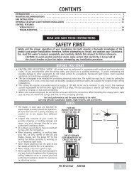
CONGRATULATIONS!<br />
Your new <strong>Hunter</strong> ceiling fan is an<br />
addition to your home or office that<br />
will provide comfort <strong>and</strong> performance<br />
for many years. This manual<br />
gives you complete instructions for<br />
installing <strong>and</strong> operating your fan.<br />
We are proud of our work. We appreciate<br />
the opportunity to supply<br />
you with the best ceiling fan available<br />
anywhere in the world.<br />
Before installing your fan, record the<br />
following information for your<br />
records <strong>and</strong> warranty assistance.<br />
Please refer to the carton <strong>and</strong> the<br />
<strong>Hunter</strong> nameplate (located on top<br />
outside fan motor housing) for the<br />
proper information.<br />
Model Name __________________<br />
Catalog No. ___________________<br />
Serial No. _____________________<br />
Date Purchased ________________<br />
Where Purchased ______________<br />
_____________________________<br />
Please attach your Hardware Sheet<br />
<strong>and</strong> Exploded View Sheet to this<br />
manual for future reference.<br />
Attach Your Receipt<br />
or a Copy of<br />
Your Receipt Here<br />
41457-01 7/2000<br />
© 2000 <strong>Hunter</strong> <strong>Fan</strong> Co.<br />
7/2000<br />
3
®<br />
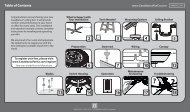
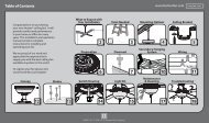
CONTENTS<br />
Important Information ....................................................................................................................................... 5<br />
Step 1 - Getting Ready ...................................................................................................................................... 6<br />
Step 2 - Installing the <strong>Ceiling</strong> Plate .................................................................................................................... 8<br />
Step 3 - Assembling Pipe/Ball Assembly ........................................................................................................... 10<br />
Step 4 - Assembling the <strong>Fan</strong> ............................................................................................................................ 12<br />
Step 5 - Hanging the <strong>Fan</strong> ................................................................................................................................ 14<br />
Step 6 - Installing the Remote ......................................................................................................................... 15<br />
Step 7 - Wiring the <strong>Fan</strong> ................................................................................................................................... 18<br />
Step 8 - Attaching the Canopy ........................................................................................................................ 20<br />
Step 9 - Assembling <strong>Fan</strong> Blades ....................................................................................................................... 21<br />
Step 10 - Attaching the Switch Housing .......................................................................................................... 23<br />
Step 11 - Installing Light Fixture ...................................................................................................................... 26<br />
Operating Your <strong>Hunter</strong> <strong>Fan</strong> <strong>and</strong> Remote ......................................................................................................... 30<br />
Cleaning <strong>and</strong> Maintenance ............................................................................................................................. 32<br />
Troubleshooting .............................................................................................................................................. 33<br />
4<br />
41457-01 7/2000
®<br />
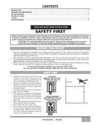
IMPORTANT INFORMATION<br />
CAUTIONS<br />
• Read entire booklet carefully<br />
before beginning installation<br />
<strong>and</strong> save these<br />
instructions.<br />
• To reduce the risk of personal<br />
injury, attach the fan<br />
directly to the support<br />
structure of the building according<br />
to these instructions,<br />
<strong>and</strong> use only the<br />
hardware supplied.<br />
WARNINGS<br />
• To avoid possible electrical<br />
shock, before installing<br />
your fan, disconnect the<br />
power by turning off the<br />
circuit breakers to the outlet<br />
box <strong>and</strong> associated wall<br />
switch location. If you can-<br />
not lock the circuit breakers<br />
in the off position, securely<br />
fasten a prominent<br />
warning device, such as a<br />
tag, to the service panel.<br />
• All wiring must be in accordance<br />
with national <strong>and</strong> local<br />
electrical codes <strong>and</strong><br />
ANSI/NFPA 70. If you are<br />
unfamiliar with wiring, you<br />
should use a qualified electrician.<br />
• To reduce the risk of personal<br />
injury, do not bend<br />
the blade attachment system<br />
when installing, balancing,<br />
or cleaning the fan.<br />
Never insert foreign objects<br />
between rotating fan<br />
blades.<br />
• To reduce the risk of fire,<br />
electrical shock, or motor<br />
damage, do not use a solidstate<br />
speed control with<br />
this fan. Use only <strong>Hunter</strong><br />
speed controls.<br />
DO YOU NEED HELP?<br />
To install a ceiling fan, be sure you<br />
can do the following:<br />
• Locate ceiling joist or other suitable<br />
support in ceiling.<br />
• Drill holes for <strong>and</strong> install wood<br />
screws.<br />
• Identify <strong>and</strong> connect electrical<br />
wires.<br />
• Lift 40 pounds.<br />
If you need help installing the fan,<br />
your <strong>Hunter</strong> fan dealer can direct you<br />
to a licensed installer or electrician.<br />
41457-01 7/2000<br />
5
®<br />
STEP 1 - GETTING READY<br />
GATHERING THE TOOLS<br />
You will need the following tools for<br />
installing the fan:<br />
• Electric drill with 9/64" bit<br />
• St<strong>and</strong>ard screwdriver<br />
• Phillips-head screwdriver<br />
• Wrench or pliers<br />
OPTIONAL ACCESSORIES<br />
Consider using <strong>Hunter</strong>’s optional accessories,<br />
including a wall-mounted<br />
or remote speed control. To install <strong>and</strong><br />
use the accessories, follow the instructions<br />
included with each product.<br />
<strong>For</strong> quiet <strong>and</strong> optimum performance<br />
of your <strong>Hunter</strong> fan, use only <strong>Hunter</strong><br />
speed controls.<br />
PREPARING THE FAN SITE<br />
The location of a ceiling fan <strong>and</strong> how<br />
the fan is attached to the building<br />
structure are essential for reliable<br />
operation, maximum efficiency, <strong>and</strong><br />
energy savings. <strong>For</strong> this reason, we<br />
have included a separate booklet —<br />
“Guide to Choosing <strong>and</strong> Preparing<br />
a <strong>Ceiling</strong> <strong>Fan</strong> Site” — to help you<br />
select the best location for your fan.<br />
The booklet also provides information<br />
to ensure your fan support <strong>and</strong><br />
electric outlet box meet UL-approved<br />
safety codes for ceiling fans.<br />
The instructions in this installation<br />
manual assume that you have used<br />
“Guide to Choosing <strong>and</strong> Preparing<br />
a <strong>Ceiling</strong> <strong>Fan</strong> Site” to pick the fan<br />
location <strong>and</strong> make certain the proper<br />
fan support <strong>and</strong> outlet box are installed.<br />
CHECKING YOUR FAN PARTS<br />
Carefully unpack your fan to avoid<br />
damage to the fan parts. Check for<br />
any shipping damage to the motor<br />
or fan blades. If one of the fan blades<br />
was damaged in shipment, return all<br />
the blades for replacement.<br />
Hint: If you are installing more than<br />
one fan, keep the fan blades<br />
in sets, as they were shipped.<br />
The fan includes a separate diagram<br />
of the screws <strong>and</strong> other small parts<br />
needed for the fan. Keep this diagram<br />
h<strong>and</strong>y for identifying parts during<br />
installation; the diagram indicates<br />
the step in which each part is used.<br />
If any parts are missing or damaged,<br />
contact your <strong>Hunter</strong> dealer or call<br />
<strong>Hunter</strong> Parts Department at<br />
901-248-2222.<br />
6<br />
41457-01 7/2000
®<br />
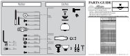
INSTALLER’S CHOICE®<br />
This patented 3-position mounting<br />
system provides you maximum installation<br />
flexibility <strong>and</strong> ease. You can<br />
install your <strong>Hunter</strong> fan in one of three<br />
ways. The steps in this manual include<br />
specific instructions for the fan<br />
mounting method of your choice. <strong>For</strong><br />
a ceiling 8 feet or higher, st<strong>and</strong>ard<br />
mounting is recommended.<br />
Flush Mounting (Figure 1a) fits<br />
close to the ceiling, for low ceilings<br />
less than 8 feet high.<br />
St<strong>and</strong>ard Mounting (Figure 1b)<br />
hangs from the ceiling by a connector<br />
pipe (included), for ceilings 8 feet<br />
or higher. <strong>For</strong> ceilings higher than<br />
eight feet, you can purchase <strong>Hunter</strong><br />
extension rods. All <strong>Hunter</strong> fans use<br />
sturdy 3/4" diameter pipe to assure<br />
stability <strong>and</strong> wobble-free performance.<br />
Angle Mounting (Figure 1c) hangs<br />
from a vaulted or angled ceiling.<br />
34° Max<br />
Pitch<br />
12<br />
8<br />
10"<br />
12"<br />
Figure 1a - Flush Mounting<br />
Figure 1b - St<strong>and</strong>ard Mounting<br />
Figure 1c - Angle Mounting<br />
41457-01 7/2000<br />
7
®<br />
STEP 2 - INSTALLING THE CEILING PLATE<br />
1. Drill two pilot holes into the wood<br />
support structure through the<br />
outermost holes on the outlet<br />
box. The pilot holes should be<br />
9/64" in diameter by 2 3/4" in<br />
depth.<br />
2. Bring the lead wires around the<br />
sides of the ceiling plate. Threading<br />
the lead wires through the<br />
hole in the middle may cause<br />
problems when installing the remote<br />
<strong>and</strong> trying to close the<br />
canopy.<br />
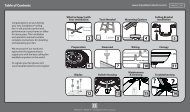
3. Your fan comes with two neoprene<br />
noise isolators. Position the<br />
isolators between the ceiling plate<br />
<strong>and</strong> ceiling by inserting the raised<br />
areas on each isolator into the<br />
holes in the ceiling plate. Refer to<br />
Figure 2a.<br />
4. Align the slotted holes in the ceiling<br />
plate with the pilot holes in<br />
the wood support structure.<br />
Note: The isolation pads should<br />
be flush against the ceiling.<br />
<strong>Ceiling</strong><br />
Plate<br />
Isolators<br />
Figure 2a - Adding Isolators to <strong>Ceiling</strong><br />
Plate<br />
<strong>For</strong> Angle Mounting Only: Be<br />
sure to orient the ceiling plate so<br />
that the two hooks point up towards<br />
the ceiling peak as shown<br />
in Figure 2b. Note: You will use<br />
the hooks to support the fan<br />
while wiring the fan.<br />
<strong>Ceiling</strong> Plate<br />
Hooks<br />
Figure 2b - Correct Position of <strong>Ceiling</strong><br />
Plate for Angle Mounting<br />
8<br />
41457-01 7/2000
®<br />
5. Place a flat washer on each of the<br />
two 3" screws <strong>and</strong> pass the<br />
screws through the slotted holes<br />
in the ceiling plate as shown in<br />
Figure 2c.<br />
6. Tighten the screws into the 9/64"<br />
pilot holes; do not use lubricants<br />
on the screws. Do not overtighten.<br />
<strong>Ceiling</strong> Joist<br />
2 x 4 Brace<br />
<strong>Ceiling</strong><br />
Plate<br />
Flat<br />
Washer<br />
<strong>Ceiling</strong><br />
Outlet Box<br />
3" Wood<br />
Screw<br />
Figure 2c - Attaching <strong>Ceiling</strong> Plate to<br />
2 x 4 Brace<br />
41457-01 7/2000<br />
9
®<br />
STEP 3 - ASSEMBLING PIPE/BALL ASSEMBLY<br />
As discussed in STEP 1 - GETTING<br />
READY, your <strong>Hunter</strong> fan can be installed<br />
in a st<strong>and</strong>ard mounting position.<br />
Included with the fan are two pipes:<br />
one 3" long pipe/ball assembly for<br />
st<strong>and</strong>ard mounting on 8' ceilings <strong>and</strong><br />
one 12" long pipe for 9' ceilings <strong>and</strong><br />
higher. See Figure 3a.<br />
If you are going to install the fan using<br />
the st<strong>and</strong>ard mounting, go to<br />
STEP 4 - ASSEMBLING THE FAN.<br />
If you are going to install the fan using<br />
the 12" long pipe for 9' ceilings<br />
or higher, complete the steps below.<br />
12" Pipe<br />
3" Pipe/Ball<br />
Assembly<br />
Figure 3a - Pipes<br />
REMOVING BALL ASSEMBLY<br />
<strong>For</strong> the following steps refer to<br />
Figures 3b <strong>and</strong> 3c.<br />
1. Locate the 3" pipe/ball assembly.<br />
2. Remove the positioning screw<br />
from the top of the ball.<br />
NOTE: The ball will become<br />
loose <strong>and</strong> should slide down the<br />
pipe.<br />
3. Remove the ball from the pipe.<br />
4. Remove the pin from the pipe.<br />
Leadwire<br />
Assembly<br />
Ground<br />
Screw<br />
Positioning Screw<br />
Pin<br />
Ball<br />
Figure 3b - Removing ball assembly<br />
continued<br />
10<br />
41457-01 7/2000
®<br />
5. Carefully loosen <strong>and</strong> remove the<br />
ground screw/leadwire assembly<br />
from the pipe.<br />
6. Locate the 12" pipe.<br />
7. Insert <strong>and</strong> tighten the ground<br />
screw/leadwire assembly into the<br />
small screw hole on one end of<br />
the 12" pipe.<br />
CAUTION<br />
Make sure that the leadwire<br />
assembly is pointing straight<br />
up <strong>and</strong> away from the pipe.<br />
WARNING<br />
• To avoid possible electrical<br />
shock, the ground screw<br />
must be tightened securely.<br />
8. Insert the pin into the two holes<br />
in the 12" pipe so that the pin is<br />
placed evenly in the hole.<br />
9. Insert the threaded end of the<br />
pipe into the flat side of the ball.<br />
10.Align the cutouts in the ball with<br />
the pin <strong>and</strong> the ground screw assembly.<br />
11.Slide the ball up the pipe until it<br />
hits the pin.<br />
12.Insert <strong>and</strong> tighten the positioning<br />
screw into the ball so that the<br />
head of the screw is tight on the<br />
end of the pipe.<br />
NOTE: Make sure that the ball<br />
is positioned so that it is level or<br />
straight.<br />
Figure 3c - 12" pipe assembly<br />
CAUTION<br />
Do not overtighten the positioning<br />
screw as it may cause<br />
the ball to seat improperly, resulting<br />
in fan wobble <strong>and</strong> the<br />
fan hanging crookedly.<br />
WARNING<br />
• Failure to complete the<br />
steps above properly could<br />
result in the fan falling.<br />
41457-01 7/2000<br />
11
®<br />
STEP 4 - ASSEMBLING THE FAN<br />
Use the Step 4 instructions for the<br />
type of mounting you have selected:<br />
st<strong>and</strong>ard, angle, or flush.<br />
STANDARD AND ANGLE<br />
MOUNTING<br />
<strong>For</strong> St<strong>and</strong>ard 8-foot <strong>Ceiling</strong>s <strong>and</strong><br />
Higher<br />
1. Insert the pipe through the<br />
canopy as shown in Figure 4a.<br />
Canopy<br />
Pipe<br />
Pipe<br />
Setscrew<br />
Figure 4a - Inserting Pipe through<br />
Canopy<br />
Feed wires from the fan through<br />
the canopy then through the<br />
pipe.<br />
2. Screw pipe into fan assembly until<br />
tight. IMPORTANT! Tighten<br />
pipe setscrew as shown in Figure<br />
4a.<br />
CAUTION<br />
The pipe has a special coating<br />
on the threads. Do not remove<br />
this coating; the coating prevents<br />
the pipe from unscrewing.<br />
Once assembled, do not<br />
remove the pipe.<br />
FLUSH MOUNTING<br />
<strong>For</strong> Low <strong>Ceiling</strong>s<br />
1. Tighten or remove pipe setscrew.<br />
Fit the canopy over the hanger<br />
adapter as shown in Figure 4b.<br />
Make sure the canopy fits snugly<br />
against the fan assembly with no<br />
space between the pieces.<br />
2. You will find a large assembly<br />
washer included with the fan.<br />
Place the washer over the adapter<br />
<strong>and</strong> canopy as shown in Figure<br />
4b.<br />
Assembly<br />
Washer<br />
Canopy<br />
Adapter<br />
Top of <strong>Fan</strong><br />
Figure 4b - Placing Canopy <strong>and</strong><br />
Washer Over Adapter<br />
12<br />
41457-01 7/2000
®<br />
3. Position the slots in the assembly<br />
washer over the threaded<br />
holes in the adapter as shown<br />
in Figure 4c.<br />
Adapter<br />
Threaded<br />
Hole<br />
4. Attach the canopy tightly to the<br />
fan assembly with three #8-32<br />
assembly screws <strong>and</strong> lockwashers<br />
as shown in Figure 4d.<br />
Assembly Screw<br />
<strong>and</strong> Lockwasher<br />
Assembly<br />
Washer<br />
Figure 4c - Positioning Assembly<br />
Washer Slots over Threaded Holes<br />
Figure 4d - Attaching Canopy to <strong>Fan</strong><br />
Assembly<br />
41457-01 7/2000<br />
13
®<br />
STEP 5 - HANGING THE FAN<br />
1. Disconnect the power by turning<br />
off the circuit breakers to the outlet<br />
box <strong>and</strong> associated wall switch<br />
location.<br />
2. Tilt <strong>and</strong> hang the assembled fan<br />
from the ceiling plate hooks. Slip<br />
two rectangular canopy slots over<br />
ceiling plate hooks as shown in<br />
Figures 5a <strong>and</strong> 5b.<br />
Note: To hang the fan you must<br />
tilt the canopy to an almost vertical<br />
position so the canopy slots<br />
come down over the ceiling plate<br />
hooks.<br />
If you are installing the remote<br />
continue to STEP 6, INSTALLING<br />
THE REMOTE, otherwise skip to<br />
STEP 7, WIRING THE FAN, on page<br />
18.<br />
<strong>Ceiling</strong><br />
Plate<br />
Figure 5a - Attaching Slots on Canopy<br />
to <strong>Ceiling</strong> Plate Hooks<br />
Figure 5b - Assembled <strong>Fan</strong> Hanging<br />
from <strong>Ceiling</strong> Plate Hooks<br />
14<br />
41457-01 7/2000
®<br />
STEP 6 - INSTALLING THE REMOTE<br />
Remote Model #: UC7067RC<br />
Ratings: 120 VAC, 60 Hz, 1.0 Amp <strong>Fan</strong><br />
250 Watts inc<strong>and</strong>escent light<br />
WARNINGS<br />
• To avoid possible electrical<br />
shock, before installing the<br />
remote, be sure that all<br />
power is disconnected by<br />
turning off the circuit<br />
breakers to the outlet box.<br />
• All wiring must be performed<br />
in accordance with<br />
national <strong>and</strong> local electrical<br />
codes. If you are unfamiliar<br />
with the wiring codes,<br />
you should use a qualified<br />
electrician.<br />
• To avoid overheating <strong>and</strong><br />
possible damage to other<br />
equipment, do not install<br />
to control a receptacle,<br />
fluorescent light fixture,<br />
motor operated appliance,<br />
or transformer-supplied<br />
appliance. Use only to control<br />
one paddle-blade ceiling<br />
fan <strong>and</strong> inc<strong>and</strong>escent<br />
light fixture.<br />
Note: This device complies<br />
with Part 15 of the FCC<br />
Rules. <strong>Operation</strong> is subject<br />
to the following two conditions:<br />
(1) this device may not<br />
cause harmful interference,<br />
<strong>and</strong> (2) this device must accept<br />
any interference received,<br />
including interference<br />
that may cause undesired<br />
operation.<br />
SETTING UP THE TRANSMITTER<br />
1. Remove the battery cover from<br />
the transmitter by pressing down<br />
on the arrow <strong>and</strong> sliding the cover<br />
off. Refer to Figure 6a.<br />
Dip Switches<br />
Battery Cover<br />
9 Volt Battery<br />
Figure 6a - Setting the Code on the<br />
Transmitter<br />
continued<br />
41457-01 7/2000<br />
15
®<br />
2. Slide the dip switches to the desired<br />
on/off position using a ballpoint<br />
pen or small-head screwdriver.<br />
Remember the on/off position<br />
of the switches for use<br />
when setting up the receiver.<br />
Note: Be sure to change the factory<br />
default switch settings to<br />
your own unique code.<br />
3. Install a 9 volt battery (not included).<br />
Refer to Figure 6a on<br />
page 15.<br />
Note: To prevent damage to the<br />
transmitter, remove the battery<br />
if it is not used for long periods<br />
of time.<br />
4. Replace the battery cover on the<br />
transmitter.<br />
5. Mount the remote holder using<br />
the two screws provided with the<br />
remote kit. Slide out center piece<br />
on the holder to see screw holes.<br />
Replace center piece after mounting<br />
to wall. Refer to Figure 6b.<br />
6. The transmitter can be placed on<br />
the remote holder for convenience<br />
or safe-keeping.<br />
Screw Hole<br />
Cover<br />
Screw Hole<br />
Screw Hole<br />
Figure 6b - Mounting the Remote<br />
Holder<br />
INSTALLING THE RECEIVER<br />
1. Slide the dip switches to the same<br />
on/off position as the transmitter<br />
using a ball-point pen or smallhead<br />
screwdriver. Refer to Figure<br />
6c.<br />
Dip Switches<br />
ON<br />
ON<br />
1 2 3 4<br />
Figure 6c - Setting the Code on the<br />
Receiver<br />
16<br />
41457-01 7/2000
®<br />
2. Make wiring connections using<br />
the wire nuts supplied. To connect<br />
the wires, place bare metal<br />
leads together. Place a wire nut<br />
over the intertwined length of<br />
wire <strong>and</strong> twist clockwise until<br />
tight as shown. Refer to Figure<br />
6d.<br />
Black/<br />
White<br />
Black/<br />
White<br />
White<br />
3. Place receiver inside the canopy<br />
under the ceiling plate. Refer to<br />
Figure 6e. Be sure to keep the<br />
antenna positioned securely on<br />
top of the receiver. Do not modify<br />
or damage the antenna wire, as<br />
control performance may be reduced.<br />
Black<br />
Black<br />
White<br />
Note: <strong>For</strong> optimal performance,<br />
the antenna should extend outside<br />
the canopy.<br />
4. Continue to STEP 8, HANGING<br />
THE FAN, on page 20.<br />
<strong>Ceiling</strong><br />
Plate<br />
Antenna<br />
Receiver<br />
Antenna<br />
White<br />
Black<br />
AC<br />
Power<br />
In<br />
Figure 6d - Wiring the Receiver<br />
Connect .............................................................................................................. To<br />
Green wire from fan .................................................................... Bare ground wire<br />
Black wire from receiver .............................................................. Black supply wire<br />
White wire from receiver ............................................................ White supply wire<br />
White wire from receiver ......................................................... White wire from fan<br />
Black wire from receiver ........................................................... Black wire from fan<br />
Black/White wire from receiver .................................... Black/White wire from light<br />
Canopy<br />
Figure 6e - Positioning the Receiver<br />
Inside of the Canopy<br />
WARNING<br />
Once receiver is installed <strong>and</strong><br />
power is turned back on, DO<br />
NOT pull the fan or light chains<br />
while power is connected.<br />
41457-01 7/2000<br />
17
®<br />
STEP 7 - WIRING THE FAN<br />
1. You can use either one or two<br />
wall switches to control the fan<br />
<strong>and</strong>/or lights separately. Use connection<br />
1 on page 19 to<br />
• control the light with a wall<br />
switch <strong>and</strong> the fan with a<br />
chain pull (one wall switch required)<br />
• control the light with a chain<br />
pull <strong>and</strong> the fan with a wall<br />
switch (one wall switch required)<br />
• control the light with one wall<br />
switch <strong>and</strong> the fan with another<br />
(two wall switches required)<br />
Use connection 2 on page 19 if<br />
there is no separate wall switch<br />
power wire for the light fixture.<br />
Note: Wall switches not included.<br />
2. Connect the wires as shown in<br />
Figure 7a. To connect the wires,<br />
place the bare metal leads together.<br />
Place a wire nut over the<br />
intertwined length of wire <strong>and</strong><br />
twist clockwise until tight as<br />
shown.<br />
3. Separate the connected wires by<br />
placing the green <strong>and</strong> white wires<br />
on one side of the outlet box <strong>and</strong><br />
the black <strong>and</strong> the black/white<br />
wires on the other side of the<br />
outlet box.<br />
4. Turn the connectors upward. Push<br />
the wires gently into the outlet<br />
box.<br />
CAUTION<br />
Be sure no bare wire or wire<br />
str<strong>and</strong>s are visible after making<br />
connections.<br />
continued<br />
18<br />
41457-01 7/2000
®<br />
Wall Switch Wire <strong>For</strong><br />
Separate Control of Light Fixture<br />
Power<br />
Wires<br />
In<br />
<strong>Ceiling</strong><br />
Black<br />
White<br />
Bare or Green<br />
(Note: Wall switch<br />
must be acceptable<br />
as a general-use<br />
switch.)<br />
2 x 4 Brace<br />
Outlet Box<br />
Approved<br />
Connectors<br />
Green<br />
Green Ground<br />
Wire from Hanger<br />
Pipe (not present<br />
with flush mounting<br />
option)<br />
White<br />
Black<br />
1<br />
2 Connections:<br />
Black/White<br />
3 Wires<br />
From <strong>Fan</strong><br />
<strong>Ceiling</strong><br />
Plate<br />
1 Connect Blk/Wht Wire from fan<br />
to Wall Switch Wire for separate<br />
control of light fixture, or<br />
2 Connect Blk/Wht Wire from fan<br />
to <strong>Ceiling</strong> Black Wire if there<br />
is no separate Wall Switch Wire<br />
for the light fixture.<br />
Figure 7a - Wiring The <strong>Fan</strong><br />
41457-01 7/2000<br />
19
®<br />
STEP 8 - ATTACHING THE CANOPY<br />
Sub-steps 1 <strong>and</strong> 2 apply to Flush,<br />
St<strong>and</strong>ard, <strong>and</strong> Angle mounting. Substep<br />
3 applies to St<strong>and</strong>ard <strong>and</strong> Angle<br />
mounting only.<br />
1. Swing the fan up so as to align<br />
the canopy screw holes with the<br />
mounting holes on the ceiling<br />
plate. Refer to Figure 8a.<br />
<strong>Ceiling</strong><br />
Plate<br />
Canopy<br />
2. Install <strong>and</strong> tighten the two #10-<br />
32 x 1/2" mounting screws.<br />
3. <strong>For</strong> St<strong>and</strong>ard <strong>and</strong> Angle<br />
Mounting Only: In addition to<br />
sub-steps 1 <strong>and</strong> 2, lift the fan<br />
housing towards the ceiling <strong>and</strong><br />
rotate the fan until each canopy<br />
tab engages a groove in the<br />
hanger ball as shown in Figure 8b.<br />
Note: If the tabs are already engaged,<br />
do not rotate.<br />
WARNING<br />
Failure to complete sub-steps<br />
1 through 3 could cause fan to<br />
fall. (Sub-step 3 not applicable<br />
for flush mounting.)<br />
Groove in<br />
Hanger<br />
Ball<br />
Canopy<br />
Tab<br />
Groove in<br />
Hanger Ball<br />
Figure 8b - Canopy Tabs <strong>and</strong> Grooves<br />
in Hanger Ball<br />
Figure 8a - Attaching Canopy to<br />
<strong>Ceiling</strong> Plate<br />
20<br />
41457-01 7/2000
®<br />
STEP 9 - ASSEMBLING FAN BLADES<br />
<strong>Hunter</strong> fans use several styles of fan<br />
blade irons (brackets that hold the<br />
blade to the fan).<br />
1. Your fan may include blade grommets<br />
(see Parts List). If your fan<br />
has grommets, insert them by<br />
h<strong>and</strong> into the holes as shown in<br />
Figure 9a.<br />
2. Attach each blade to blade iron<br />
using three blade assembly screws<br />
as shown in Figure 9b. Some fans<br />
Grommet<br />
feature a decorative medallion as<br />
well as a blade iron. Insert the<br />
assembly screws into the blade<br />
iron, through the blade <strong>and</strong> into<br />
the medallion, with the blade<br />
s<strong>and</strong>wiched between the blade<br />
iron <strong>and</strong> medallion as shown in<br />
Figure 9c.<br />
If you used grommets, the blades<br />
may appear slightly loose after<br />
screws are tightened. This is normal.<br />
3. Remove the blade mounting<br />
screws <strong>and</strong> rubber shipping<br />
bumpers from the motor.<br />
Blade<br />
Iron<br />
<strong>Fan</strong><br />
Blade<br />
Medallion<br />
Figure 9a - Inserting Grommet into<br />
<strong>Fan</strong> Blade<br />
Figure 9b - Attaching <strong>Fan</strong> Blade to<br />
Blade Iron<br />
Figure 9c - Attaching <strong>Fan</strong> Blade to<br />
Blade Iron using Decorative Medallion<br />
41457-01 7/2000<br />
21
®<br />
4. <strong>For</strong> each blade, insert one blade<br />
mounting screw through the<br />
blade iron as shown in Figure 9d,<br />
<strong>and</strong> attach lightly to the fan. Insert<br />
the second blade mounting<br />
screw, then securely tighten both<br />
mounting screws.<br />
Figure 9d - Attaching Blade Irons to<br />
Hub of <strong>Fan</strong> Assembly<br />
22<br />
41457-01 7/2000
®<br />
STEP 10 - ATTACHING THE SWITCH HOUSING<br />
The switch housing is made up of<br />
two sections: the upper switch housing,<br />
<strong>and</strong> the lower switch housing.<br />
ATTACHING THE UPPER SWITCH<br />
HOUSING<br />
1. Partially install two #6-32 x 3/8"<br />
housing assembly screws into the<br />
switch housing mounting plate as<br />
shown in Figure 10a.<br />
Switch<br />
Housing<br />
Mounting<br />
Plate<br />
Upper<br />
Switch<br />
Housing<br />
Housing<br />
Assembly<br />
Screw<br />
Upper Plug<br />
Connector<br />
Figure 10a - Attaching Upper Switch<br />
Housing to Switch Housing Mounting<br />
Plate<br />
2. Feed the upper plug connector<br />
through the center opening of the<br />
upper switch housing. See Figure<br />
10a.<br />
3. Align the keyhole slots in the upper<br />
switch housing with the housing<br />
assembly screws installed in<br />
sub-step 1.<br />
4. Turn the upper switch housing<br />
counterclockwise until the housing<br />
assembly screws are firmly<br />
situated in the narrow end of the<br />
keyhole slots as shown in Figure<br />
10b. Install the one remaining #6-<br />
32 x 3/8" housing assembly screw<br />
into the third hole in the upper<br />
switch housing. Tighten all three<br />
screws firmly.<br />
CAUTION<br />
Make sure the upper switch<br />
housing is securely attached to<br />
the switch housing mounting<br />
plate. Failure to properly attach<br />
<strong>and</strong> tighten all three housing<br />
assembly screws could result<br />
in the switch housing <strong>and</strong><br />
light fixture falling.<br />
Figure 10b - Mounting the Upper<br />
Switch Housing<br />
41457-01 7/2000<br />
23
®<br />
ATTACHING THE LOWER<br />
SWITCH HOUSING<br />
Your hunter fan includes one of two<br />
lower switch housings. Both lower<br />
switch housings are shown in Figures<br />
10c <strong>and</strong> 10d. The type of lower<br />
switch housing you have depends on<br />
whether your fan includes a light fixture,<br />
<strong>and</strong> if so, what type of light fixture<br />
it is. Use table 10-1 to assist you.<br />
If your fan has a lower switch housing<br />
as shown in Figure 10c, <strong>and</strong> you<br />
ARE installing an accessory light kit<br />
or single-globe light fixture included<br />
with your fan, go directly to STEP<br />
11 - INSTALLING LIGHT FIXTURE.<br />
Figure 10c - Lower Switch Housing<br />
Without Light Kit or Single-Globe<br />
Light Fixture<br />
Table 10-1<br />
<strong>Fan</strong> with no light<br />
fixture included<br />
<strong>Fan</strong> with accessory<br />
light kit included<br />
<strong>Fan</strong> with multilight<br />
light fixture<br />
included<br />
See Figure 10c<br />
See Figure 10c<br />
See Figure 10d<br />
Figure 10d - Lower Switch Housing<br />
With Multi-Light Fixture<br />
continued<br />
24<br />
41457-01 7/2000
®<br />
If your fan has a lower switch housing<br />
as shown in Figure 10c <strong>and</strong> you<br />
ARE NOT installing a light fixture, or<br />
if your fan has a lower switch housing<br />
as shown in Figure 10d, complete<br />
the following steps:<br />
1. Connect the upper plug connector<br />
from the motor to the lower<br />
plug connector in the lower<br />
switch housing assembly. See Figure<br />
10e.<br />
Note: Both plug connectors are<br />
polarized <strong>and</strong> will only fit together<br />
one way. Make sure that both<br />
connectors are properly aligned<br />
before connecting them together.<br />
Incorrect connection could cause<br />
improper operation <strong>and</strong> damage<br />
to the product.<br />
Lower Plug<br />
Connector<br />
Housing<br />
Assembly<br />
Screw<br />
Upper<br />
Switch<br />
Housing<br />
Upper Plug<br />
Connector<br />
Figure 10e - Plug Connection <strong>and</strong><br />
Lower Switch Housing <strong>Installation</strong><br />
Lower<br />
Switch<br />
Housing<br />
2. Place the lower switch housing<br />
assembly over the upper switch<br />
housing. Align the side screw<br />
holes in the upper <strong>and</strong> lower<br />
switch housings. Attach the lower<br />
switch housing to the upper<br />
switch housing with three #6-32<br />
x 3/8" housing assembly screws.<br />
See Figure 10e.<br />
Note: If your fan does not include<br />
a light fixture, you may purchase<br />
an accessory light kit separately.<br />
See STEP 11 - INSTALLING LIGHT<br />
FIXTURE.<br />
41457-01 7/2000<br />
25
®<br />
26<br />
STEP 11 - INSTALLING LIGHT FIXTURE<br />
Your fan may include a light fixture.<br />
Information for wiring <strong>and</strong> installing<br />
all included <strong>Hunter</strong> light fixtures follows.<br />
Note: If you purchased a fan without<br />
a light fixture, you may purchase<br />
an accessory light kit separately. <strong>For</strong><br />
best performance <strong>and</strong> beauty, use<br />
only <strong>Hunter</strong>-br<strong>and</strong> light kits, Type A-<br />
Z. <strong>Hunter</strong> light kits are designed,<br />
tested, <strong>and</strong> UL approved for all<br />
<strong>Hunter</strong> fans, <strong>and</strong> are available at<br />
most <strong>Hunter</strong> dealers. To install the<br />
light kit, follow the instructions included<br />
with the kit.<br />
If you are not installing a light fixture,<br />
turn to OPERATING YOUR<br />
HUNTER FAN for additional instructions.<br />
WARNING<br />
• To avoid possible electrical<br />
shock, before installing<br />
light fixtures, disconnect<br />
power by turning off the<br />
circuit breakers both to the<br />
outlet box <strong>and</strong> to its associated<br />
wall switch location.<br />
If you cannot lock the circuit<br />
breakers in the off position,<br />
securely fasten a<br />
prominent warning device,<br />
such as a tag, to the service<br />
panel.<br />
• Connect house wiring to<br />
the fan before attaching<br />
the light fixture to the fan.<br />
• All wiring must be in accordance<br />
with national <strong>and</strong> local<br />
electrical codes <strong>and</strong><br />
ANSI/NFPA 70. If you are<br />
unfamiliar with wiring, you<br />
should use a qualified electrician.<br />
INSTALLING INCLUDED ACCES-<br />
SORY LIGHT KIT<br />
1. Remove the plug <strong>and</strong> switch<br />
housing caps from the lower<br />
switch housing. Refer to Figure<br />
11a.<br />
Note: Do not discard the caps.<br />
You will need this if you remove<br />
the light fixture in the future.<br />
2. Locate the white wire <strong>and</strong> the<br />
black wire coming from the light<br />
fixture.<br />
3. Thread the two wires from the<br />
light fixture through the center<br />
hole in the lower switch housing.<br />
Be sure to thread the black wire<br />
with the larger connector head<br />
through first <strong>and</strong> then thread the<br />
white wire with the smaller connector<br />
head through.<br />
41457-01 7/2000
®<br />
Lower<br />
Switch<br />
Housing<br />
Switch<br />
Housing<br />
Cap<br />
Plug Button<br />
the wires. Making sure the light<br />
fixture mounting screw holes are<br />
aligned; hold the light fixture <strong>and</strong><br />
tighten the nut on the inside of<br />
the lower switch housing. Insert<br />
<strong>and</strong> tighten the two #6-32 sems<br />
light fixture mounting screws.<br />
5. Refer to Figure 11b. Locate the<br />
black/white wire <strong>and</strong> the white<br />
wire in the fan switch housing<br />
that have connectors attached.<br />
Pull the dummy terminals out of<br />
both connectors. Connect the<br />
black/white wire to the black wire<br />
of the light kit. Connect the white<br />
CAUTION<br />
Be sure no bare wire or wire<br />
str<strong>and</strong>s are visible after making<br />
connections.<br />
wire to the white wire of the light<br />
kit.<br />
6. Connect the upper plug connector<br />
from the motor to the lower<br />
plug connector in the lower<br />
switch housing assembly. See Figure<br />
10e on page 25.<br />
Dummy Terminals<br />
(to be removed when<br />
hooking up light kit)<br />
Figure 11a - Removing Plug Button<br />
<strong>and</strong> Switch Housing Cap<br />
4. Screw the fixture into the lower<br />
switch housing. Thread the<br />
lockwasher <strong>and</strong> nut provided over<br />
Wires From<br />
The <strong>Fan</strong><br />
Figure 11b - Wiring Connections for Light Kit<br />
Wires From<br />
The Light Kit<br />
continued<br />
41457-01 7/2000<br />
27
®<br />
Note: Both plug connectors are<br />
polarized <strong>and</strong> will only fit together<br />
one way. Make sure that both<br />
connectors are properly aligned<br />
before connecting them together.<br />
Incorrect connection could cause<br />
improper operation <strong>and</strong> damage<br />
to the product.<br />
7. Place the lower switch housing<br />
assembly over the upper switch<br />
housing. Align the side screw<br />
holes in the upper <strong>and</strong> lower<br />
switch housings. Attach the lower<br />
switch housing to the upper<br />
switch housing with three #6-32<br />
x 3/8" housing assembly screws.<br />
See Figure 10e on page 25.<br />
INSTALLING INCLUDED ACCES-<br />
SORY LIGHT FIXTURE GLOBES<br />
AND BULBS<br />
1. Place globe over threaded<br />
lampholder in cup. Install <strong>and</strong><br />
h<strong>and</strong> tighten threaded locking<br />
ring on lampholder as shown in<br />
Figures 11c <strong>and</strong> 11d.<br />
2. Install bulbs. Use 120V, 60W<br />
maximum medium base inc<strong>and</strong>escent<br />
bulbs. Turn power ON at<br />
main panel.<br />
Cup<br />
Threaded<br />
Lamp Holder<br />
Note: As shown in Figure 11d,<br />
line up the beginning of the first<br />
thread on the lampholder <strong>and</strong><br />
notch on the locking ring to<br />
avoid cross threading the ring.<br />
If the ring becomes hard to turn,<br />
rotate the ring counter clockwise<br />
to loosen <strong>and</strong> reposition. Do not<br />
force the ring on.<br />
Notch in Ring<br />
Beginning of<br />
First Thread<br />
Threaded<br />
Locking Ring<br />
Figure 11d - Assembling the Locking<br />
Ring<br />
Globe<br />
Threaded<br />
Locking Ring<br />
Figure 11c - Installing the Globes<br />
28<br />
41457-01 7/2000
®<br />
INSTALLING SINGLE-GLOBE<br />
FIXTURE BULB AND GLOBE<br />
Refer to Figure 11e.<br />
1. Install light bulbs.<br />
2. Insert the globe around the bulb<br />
<strong>and</strong> into the fixture. Install <strong>and</strong><br />
tighten thumbscrews manually.<br />
Do not overtighten.<br />
Thumbscrew<br />
INSTALLING INTEGRATED MULTI-<br />
LIGHT FIXTURE BULBS AND<br />
GLOBES<br />
Refer to Figure 11f.<br />
1. Place silencer b<strong>and</strong> around the<br />
neck of each globe.<br />
2. Insert globe in cup.<br />
3. Install <strong>and</strong> tighten thumbscrews<br />
manually. Do not overtighten.<br />
4. Install bulbs.<br />
INSTALLING ACCESSORY LIGHT<br />
KITS<br />
To install the light kit, follow the instructions<br />
included with the kit for<br />
wiring, mounting, <strong>and</strong> assembly. After<br />
completing the light kit installation,<br />
follow sub-steps 1 <strong>and</strong> 2 on<br />
page 23 to reattach the lower switch<br />
housing.<br />
Globe<br />
Thumbscrew<br />
Bulb<br />
Figure 11e - Single-Globe Fixture<br />
Cup<br />
Globe<br />
Silencer<br />
B<strong>and</strong><br />
Figure 11f - Multi-Light Fixture<br />
41457-01 7/2000<br />
29
®<br />
OPERATING YOUR HUNTER FAN AND REMOTE<br />
Your <strong>Hunter</strong> <strong>Fan</strong> comes with an<br />
acessory pull chain pendant for both<br />
fan <strong>and</strong> light operation. To install the<br />
pull chain pendants, insert the loose<br />
end of the pull chain pendant into<br />
the breakaway connector on the fan<br />
<strong>and</strong> light pull chains.<br />
OPERATING YOUR HUNTER FAN<br />
WITHOUT REMOTE<br />
1. Turn on electrical power to the<br />
fan.<br />
2. The pull chain controls power to<br />
the fan. The chain has four settings<br />
in sequence: High, Medium,<br />
Low <strong>and</strong> Off.<br />
• Pull the chain slowly to change<br />
settings.<br />
• Release slowly to prevent the<br />
chain from recoiling into the<br />
blades.<br />
• The chain uses a breakaway<br />
connector that separates if the<br />
chain is jerked. If this happens,<br />
simply reinsert the chain into<br />
the connector.<br />
3. <strong>Ceiling</strong> fans work best by blowing<br />
air downward (counterclockwise<br />
blade rotation) in warm<br />
weather to cool the room with a<br />
Figure 12a - Air Flow Patterns<br />
direct breeze. In winter, having<br />
the fan draw air upward (clockwise<br />
blade rotation) will distribute<br />
the warmer air trapped at the<br />
ceiling around the room without<br />
causing a draft. Refer to Figure<br />
12a.<br />
To change the direction of air<br />
flow, turn the fan off <strong>and</strong> let it<br />
come to a complete stop. Slide<br />
the reversing switch on the fan<br />
to the opposite position as shown<br />
in Figure 12b. Restart fan.<br />
4. If your fan wobbles when operating,<br />
use the enclosed balancing<br />
kit <strong>and</strong> instructions to balance the<br />
fan.<br />
Pull<br />
Chain<br />
Reversing<br />
Switch<br />
Figure 12b - Pull Chain <strong>and</strong> Reversing<br />
Switch<br />
30<br />
41457-01 7/2000
®<br />
OPERATING YOUR HUNTER FAN<br />
WITH A REMOTE<br />
WARNING<br />
Once receiver is installed <strong>and</strong><br />
power is turned back on, DO<br />
NOT pull the fan or light chains<br />
while power is connected.<br />
Refer to steps 1, 3, <strong>and</strong> 4 in the OP-<br />
ERATING YOUR HUNTER FAN<br />
WITHOUT A REMOTE. Use the<br />
following steps to operate your<br />
remote.<br />
1. Turn ON the wall switch. The light<br />
will turn ON at maximum brightness.<br />
2. Light <strong>Operation</strong>:<br />
Press <strong>and</strong> quickly release the light<br />
button on the h<strong>and</strong> held remote<br />
to turn the light OFF or ON.<br />
Press <strong>and</strong> hold the light button for<br />
more than 0.7 second to dim or<br />
brighten the light. Release the<br />
light button when the desired<br />
light level is reached. The light<br />
dimmer range is 20% to 100%.<br />
The Light key has auto resume,<br />
so the brightness will stay the<br />
same as the last time it was turned<br />
OFF. Refer to Figure 12c.<br />
3. <strong>Fan</strong> <strong>Operation</strong>:<br />
Press the fan button to turn ON<br />
the ceiling fan at High speed.<br />
Press again to change the speed<br />
to Medium, then again to Low,<br />
<strong>and</strong> then again to turn the fan<br />
OFF. Refer to Figure 12c.<br />
Note: If fan is not reaching desired<br />
speed or light does not<br />
come on, refer to the TROUBLE-<br />
SHOOTING section.<br />
LOW MED HIGH<br />
Display<br />
Light Button<br />
<strong>Fan</strong> Button<br />
Figure 12c - Remote Transmitter<br />
41457-01 7/2000<br />
31
®<br />
CLEANING AND MAINTENANCE<br />
Caring for finishes: <strong>For</strong> cleaning, a<br />
soft brush or lint-free cloth should<br />
be used to prevent scratching the finish.<br />
A vaccuum cleaner brush nozzle<br />
can remove heavier dust. Surface<br />
smudges or an accumulation of dirt<br />
<strong>and</strong> dust can easily be removed by<br />
using a mild detergent <strong>and</strong> a slightly<br />
dampened cloth. An artistic agent<br />
may be used, but never use abrasive<br />
cleaning agents as they will damage<br />
the finish.<br />
Caring for blades: Wood finish<br />
blades should be cleaned with a furniture<br />
polishing cloth. Occasionally,<br />
a light coat of furniture polish may<br />
be applied for added protection <strong>and</strong><br />
beauty. Painted <strong>and</strong> high-gloss<br />
blades may be cleaned in the same<br />
manner as the fan finish.<br />
MANUFACTURER'S<br />
PHONE NUMBER<br />
If you need parts or service<br />
asssitance, please call 901-248-2222<br />
or visit us at our WEB site at:<br />
http://www.hunterfan.com<br />
32<br />
41457-01 7/2000
TROUBLESHOOTING<br />
PROBLEM PROBABLE CAUSE SOLUTION<br />
Nothing happens; fan does not move.<br />
Without Remote (refer to page 35 for<br />
troubleshooting With Remote).<br />
1. Power turned off, fuse blown, or<br />
circuit breaker tripped.<br />
2. Loose wire connections or wrong<br />
connections.<br />
3. Motor reversing switch not engaged.<br />
4. Pull chain switch not “on.”<br />
5. Shipping bumpers still in place.<br />
1. Turn power on, replace fuse, or reset<br />
breaker.<br />
2a. Loosen canopy, check all connections<br />
according to STEP 7 - WIRING THE<br />
FAN (turn power off before<br />
checking).<br />
2b.Check the plug connection in the<br />
switch housing according to STEP<br />
10 - ATTACHING THE SWITCH<br />
HOUSING.<br />
3. Push switch firmly up or down.<br />
4. Pull switch chain.<br />
5. Remove shipping bumpers.<br />
®<br />
Noisy operation.<br />
1. Blade brackets screwed loosely to<br />
motor.<br />
2. Blade screwed loosely to blade iron.<br />
3. Blade cracked.<br />
1. Tighten screws until snug.<br />
2. Tighten screws until snug.<br />
3. Replace all blades.<br />
continued<br />
41457-01 7/2000<br />
33
®<br />
PROBLEM PROBABLE CAUSE SOLUTION<br />
Noisy operation (continued).<br />
4. Using non-approved speed control. 4. Change to approved speed control.<br />
5. Glass screwed loosely to fixture. 5. H<strong>and</strong>-tighten the light fixture<br />
screws. Ensure that rubber noise<br />
isolators are installed.<br />
6. Switch housing is loose.<br />
6. Check <strong>and</strong> tighten screws to the<br />
switch housing mounting plate <strong>and</strong><br />
to the upper <strong>and</strong> lower switch<br />
housing.<br />
Excessive wobbling.<br />
Note: When switching from medium<br />
to low speed, you may notice some fan<br />
wobble. When the fan stabilizes at low<br />
speed, wobble will disappear.<br />
1. Unbalanced blades.<br />
2. Loose blades or blade irons.<br />
3. <strong>Fan</strong> not secure on hanger assembly.<br />
4. <strong>Fan</strong> hanger ball not seated in<br />
canopy tabs.<br />
1. Use balancing kit included with fan.<br />
2. Tighten all screws.<br />
3. Turn power off, support fan very<br />
carefully, loosen canopy <strong>and</strong> hang<br />
correctly.<br />
4. Turn power off, support the fan<br />
very carefully, <strong>and</strong> check that the<br />
hanger ball is properly seated.<br />
If you have tried these troubleshooting solutions <strong>and</strong> still have trouble, call 901-248-2222 or visit our<br />
Web site at http://www.hunterfan.com.<br />
continued<br />
34<br />
41457-01 7/2000
®<br />
PROBLEM PROBABLE CAUSE SOLUTION<br />
No functions operate or do not operate 1. Main Power not restored. 1. Replace fuse. Turn ON circuit<br />
correctly. (With Remote)<br />
breaker. Turn ON wall switch.<br />
2. <strong>Fan</strong> pull chain not set to High. 2. Turn OFF power at wall switch<br />
or main electric panel. Set fan<br />
to High speed.<br />
3. Light pull chain not set to ON.<br />
4. Receiver wiring incorrect.<br />
3. Set light kit to ON.<br />
4. Verify wiring connections.<br />
Operates only at close range. (With Remote)<br />
5. Transmitter <strong>and</strong> receiver dip<br />
switches do not match.<br />
6. Battery too weak.<br />
1. Signal blocked from reaching<br />
receiver.<br />
2. Battery too weak.<br />
5. Set transmitter <strong>and</strong> receiver to<br />
same dip switch setting.<br />
6. Replace with new battery.<br />
1. Extend antenna into ceiling box,<br />
or move it for better reception.<br />
2. Replace with new battery.<br />
Inconsistent operation. (With Remote)<br />
1. Signal partially blocked from<br />
reaching receiver.<br />
2. RF interference.<br />
3. Continuing RF interference.<br />
1. Extend antenna into ceiling box,<br />
or move it for better reception.<br />
2. Turn OFF wall switch for 5<br />
seconds, then turn back ON.<br />
3. Change dip switch settings to a<br />
different code in both Transmitter<br />
<strong>and</strong> Receiver.<br />
41457-01 7/2000<br />
35