CN1303-4 Gas Predator Manual 2nd Edition
CN1303-4 Gas Predator Manual 2nd Edition
CN1303-4 Gas Predator Manual 2nd Edition

Create successful ePaper yourself
Turn your PDF publications into a flip-book with our unique Google optimized e-Paper software.
M3x8 Socket Cap<br />
Screws x 4 & M3<br />
Flat Washers x 4<br />
(No threadlock!)<br />
#HW6110A<br />
Upper Side<br />
Frames (Left &<br />
Right)<br />
#HI6032 Rear<br />
CCPM Lever<br />
R<br />
L<br />
M3x8 Socket<br />
Cap Screws x 4<br />
(No threadlock!)<br />
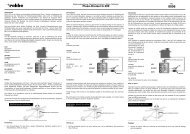
Step 35 Upper Frame Assembly<br />
Start by installing the elevator bell crank<br />
assembly, note that the left side ball<br />
bearing is flush with the pivot axle. On<br />
the right side frame, the axle extends<br />
outward from the frame to attach the<br />
elevator arm. Install four M3x8 socket<br />
cap screws into the upper main shaft<br />
bearing block, front hex spacer and<br />
forewardmost lower bearing block.<br />
Install four M3x8 socket cap screws into<br />
the clutchbell blocks with M3 flat<br />
washers. Do not use any threadlock at<br />
this time, these need to be loose until the<br />
main shaft is installed and after the gear<br />
mesh has been set.<br />
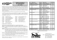
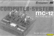
Step 36 Front CCPM Bellcranks<br />
Starting on the right side, insert one M3x30 socket cap screw through the right bellcrank (look at the left photo carefully)<br />
on the side with the molded elevator plastic arm. Slide one stepped spacer with the step towards the ball bearing and<br />
position the 26mm threaded spacer between the upper side frames in the rearmost hole (120 0 CCPM setup) and secure the<br />
right bellcrank assembly. Assemble the left side bellcrank in the same way, do not apply the threadlock until after the gear<br />
mesh has been set and tighten into the left side of the upper frames.<br />
#HI6031<br />
CCPM<br />
Cyclic<br />
Bellcrank<br />
Set<br />
#CNLR1014<br />
Short Ball x 2<br />
26mm Threaded<br />
Spacer<br />
#CNLR1020<br />
Medium Ball x 4<br />
M3x30 Socket<br />
Cap Screw x 2<br />
Stepped<br />
Spacer x 2<br />
R<br />
#CNBB37<br />
M3x7 Ball<br />
Bearing x 4<br />
Right Side<br />
Bellcrank<br />
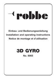
The technique to remove the two M3x30 socket cap<br />
screws without damaging the 26mm spacer is to<br />
slowly loosen each screw 1/8 turn at a time, changing<br />
from side to side to evenly unload the threaded<br />
spacer. If you notice one side spinning the spacer,<br />
tighten the opposite side again and repeat.<br />
16<br />
L