CN1303-4 Gas Predator Manual 2nd Edition
CN1303-4 Gas Predator Manual 2nd Edition
CN1303-4 Gas Predator Manual 2nd Edition

Create successful ePaper yourself
Turn your PDF publications into a flip-book with our unique Google optimized e-Paper software.
Step 1 Rotor Head Block<br />
The entire rotor head comes pre-assembled with<br />
the standard HI6181A (red) head dampers<br />
installed. 3D and aerobatic pilots should<br />
disassemble the rotorhead and install the hard<br />
HI6181B (black) head dampers. Press in the<br />
head dampers into the rotor head block. Lubricate<br />
the inside surface of each damper with<br />
light oil. Leave the M2.5 screws loose.<br />
#HI6181A<br />
Head Dampers<br />
Standard (Red) x 2<br />
Sport & Scale Flying<br />
#HI6181B<br />
Head Dampers<br />
Hard (Black) x 2<br />
3D Flying<br />
#HI6160<br />
Rotor Head Block<br />
& M2.5x8 Socket Screw x 2<br />
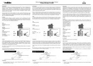
Step 2 Seesaw Assembly<br />
Insert one ball bearing into each<br />
bearing cup and insert into the offset<br />
plate. Apply one small drop of slow<br />
cyanoacrylate glue (Slow CA) to the<br />
joint between the backside of the<br />
bearing cup and the offset plate.<br />
Insert one ball bearing into each tie<br />
bar, using an available M3 socket<br />
cap screw form threads into both<br />
ends of the tie bars. Insert one M3x6<br />
button head screw through the right<br />
side hole of the offset plate (see<br />
photo) and thread into one tie bar.<br />
Make two identical sub-assemblies.<br />
Note that the bearing cups face<br />
outwards from the head block. Insert<br />
one M3x15 button head screw<br />
through the tie bar bearing, slide one<br />
steel spacer and carefully apply<br />
L242 Blue threadlock to the exposed<br />
threads and insert into the right side<br />
of the head block. Do not overtighten.<br />
Repeat for the second subassembly.<br />
Once complete apply a<br />
small amout of slow cyanoacrylate<br />
glue and insert one HI6167 special<br />
long thread ball into each offset<br />
plate to complete the assembly.<br />
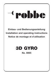
Step 3 Head Button - <strong>Gas</strong> SE<br />
#HI3167F<br />
Bearing Cups x 2<br />
#HI3167B<br />
Offset Plates x 2<br />
#HI3167G<br />
Tie Bars &<br />
Spacers<br />
M3x15 Button<br />
Head Screw<br />
#HW6001<br />
Completed rotor head.<br />
Bond bearing cup<br />
holder to metal<br />
offset plate.<br />
<strong>Gas</strong> SE only<br />
#CNBB37<br />
M3x7 Ball<br />
Bearing x 2<br />
M3 Threaded Stud<br />
#CNBB48<br />
M4x8 Ball<br />
Bearing x 2<br />
#HI6167<br />
Special Ball x 2<br />
Steel Ball on Left side.<br />
#HW6001<br />
M3x6 Button<br />
Head Screw x 2<br />
Bond the M3 threaded stud into the head button using<br />
L262 Red threadlock then apply more threadlock to the<br />
exposed threads and thread into the top of the rotor head<br />
block. Remove any extra threadlock compound.<br />
4<br />
#CN2215A<br />
Machined Head<br />
Button