CN1303-4 Gas Predator Manual 2nd Edition
CN1303-4 Gas Predator Manual 2nd Edition
CN1303-4 Gas Predator Manual 2nd Edition

Create successful ePaper yourself
Turn your PDF publications into a flip-book with our unique Google optimized e-Paper software.
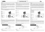
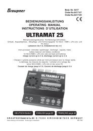
Step 7 Feathering Spindle & Blade Grip<br />
#HW6182<br />
Stiffness<br />
Shims<br />
Large<br />
#HW6180A<br />
Feathering<br />
Spindle<br />
thin<br />
race<br />
(inside)<br />
larger ID<br />
Round Recess<br />
on Top<br />
#CNBB715T<br />
M7x15 Thrust<br />
Ball Bearing<br />
#HW6180A M5x10<br />
Socket Screw & M5<br />
Flat Washer<br />
thick race<br />
(outside)<br />
smaller ID<br />
Hobby Grease<br />
Generally, grease is<br />
needed for thrust<br />
bearings and the tail<br />
rotor gears. A light<br />
Lithium or Silicon<br />
grease should be<br />
used, commonly<br />
found at hobbyshops<br />
for RC cars.<br />
Remove one damper and press the feathering spindle to seat the ball near the center of the rotor hub. Reposition the<br />
rubber damper in the rotor hub and slide one large shim against the damper followed by three regular stiffness shims and<br />
one blade grip assembly onto the feathering spindle. The bell mixer and pitch arm of the blade grip is mounted on the<br />
leading edge when as the head rotates clockwise. Install the M7x15 thrust bearing and lubricate the bearings with light<br />
grease. Looking at the two steel races of the thrust bearing, note that the innermost surfaces have different widths because<br />
the inside diameters are different. Slide the first larger diameter steel washer (thin race, larger ID) followed by the<br />
greased ball race, followed by the second steel washer (thick race, smaller ID). Remove any grease that may have<br />
transfered to the threads using a cotton swab dipped in alcohol. Apply L242 Blue threadlock to the inside threads on the<br />
feathering spindle using a pin and install the M5x10 socket cap screw with washer. Do not overtighten this bolt because<br />
it will flair the end of the spindle making removal of the blade grip nearly impossible. Repeat for the other blade grip.<br />
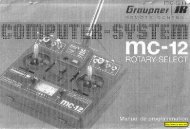
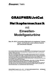
Step 8 Flybar Control Yoke<br />
M3x12 Button<br />
Cap Screw<br />
#HI3176C<br />
Flybar<br />
Control Arm<br />
M4x5 Set<br />
Screw<br />
Circle Mark<br />
presses over<br />
steel ball.<br />
#CNLR1006<br />
M4x6 Micro Washer<br />
#HW3176C Double<br />
Studded Steel Ball<br />
#HI3176C<br />
Tapered<br />
Standoff<br />
Ball Link Direction<br />
All ball links are molded to be installed in only<br />
one direction. Look carefully at the hole for the<br />
ball, one side is clean while the other side has a<br />
circular mark, 1mm larger than the hole. The<br />
marked side presses over the steel control balls.<br />
Pushrod A is already assembled but check that the<br />
length is actually 47mm (center to center). As the<br />
pushrods are build and installed they should be checked<br />
for tightness. Press one ball link onto each double<br />
studded steel ball, making sure that pressure is applied<br />
from the side of the ball link with circle mark. While<br />
holding one flybar control arm, apply a small amount of<br />
slow cyanoacrylate glue and thread one end of the<br />
double studded steel ball into each standoff. When it<br />
becomes difficult to turn with fingers, apply slow CA to<br />
the threads and start screwing in the tapered control arm<br />
stand-off on the other end of the ball.<br />
6<br />
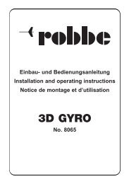
Pushrod A 47mm<br />
(center to center)<br />
#HI6145 Ball Link x 2<br />
#HW6192 25mm Pushrod x 2<br />
A correctly installed the ball link should rotate with<br />
some resistance when the metal pushrod is rotated in<br />
your fingers. If the ball link to too tight the preferred<br />
solution is to purchase Century’s ball link sizing tool<br />
[CN2055] to custom fit each ball link to its steel ball.