CN1303-4 Gas Predator Manual 2nd Edition
CN1303-4 Gas Predator Manual 2nd Edition
CN1303-4 Gas Predator Manual 2nd Edition

Create successful ePaper yourself
Turn your PDF publications into a flip-book with our unique Google optimized e-Paper software.
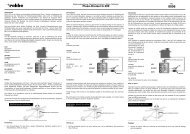
Step 56 Idle Adjustment Screw & Carburetor Spring<br />
The idle adjustment screw is used to limit the travel of the throttle<br />
valve inside the carburetor. Turn the adjustment screw until the<br />
point is flush to the bottom of the rotary lever, this will be the<br />
throttle stop position. The spring is already installed on the carburetor<br />
and should be left in place. The spring provides the necessary<br />
tension along the length of the throttle lever axle to prevent wearing<br />
of the shaft prematurely. Install the carburetor to the engine crankcase<br />
using the screws and gaskets included with the engine with the<br />
primer bubble facing rearward and the fuel fittings on top.<br />
Idle Screw, position flush to<br />
bottom of throttle lever.<br />
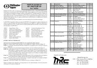
Step 57 Throttle Pushrod & Carburetor Arm<br />
Before the carburetor arm is tightened to the to the carburetor throttle shaft, the pushrod will be attached and adjusted to<br />
achieve a linear geometry that will result in a 90 0 degree angle between the pushrod and both the servo horn and the<br />
machined carburetor arm. Install one steel ball into the carburetor arm positioned in the center hole (13.5mm from the<br />
center of the arm) and the servo horn at 13.5mm, using L242 Blue threadlock. If you have not already done so, shorten the<br />
throttle pushrod from 104mm to 94mm by cutting 5mm off each end. Install the ball links and set pushrod F to 112mm<br />
center to center. Move the collective stick to the center and press the servo horn onto the servo close to the final angle.<br />
Slide the carburetor arm over the throttle lever shaft and attach Pushrod F. Using the subtrim on the throttle channel, fine<br />
tune the servo horn to achieve the 90 0 degree setting. Looking through the venturi, move the valve to the 45 0 position and<br />
lightly tighten the M3x4 set screw on the side of the carburetor arm. Check the end points and continue to adjust the set<br />
screw postion until the carburetor will move through the entire throttle range with out binding. Once complete, firmly<br />
hold the external throttle lever, remove and apply L242 Blue threadlock to the M3x4 set screw and tighten in place.<br />
90 0 Degrees<br />
90 0 Degrees<br />
Optional<br />
#CN2288 Metal<br />
Servo Arm Pack<br />
#CNLR1018 Ultra<br />
Short Steel Ball &<br />
M2 Hex Nut<br />
#HW6192C<br />
Pushrod F 112mm<br />
(center to center)<br />
#CNLR1018 Ultra<br />
Short Steel Ball &<br />
M2 Hex Nut<br />
#HW6192B<br />
Carburetor Arm &<br />
M3x4 Set Screw<br />
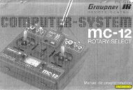
Step 58 Fuel Lines<br />
Of the three lines to the fuel tank, both the primer<br />
return line and the atmosphere line can use the 1/8”<br />
ID fuel line. The fuel pickup line on the Z231H<br />
engine should use the same 1/8” ID fuel line but use<br />
the larger 3/16” ID fuel line on the Z260H engine.<br />
The atmosphere line should run from the top of the<br />
fuel tank, upward and looped near the top of the<br />
vertical frame and then routed and tied to one of the<br />
landing gear spacers, making sure that the fuel line<br />
extends 1/4” past the plastic struts.<br />
24<br />
Tygon fuel line<br />
not included.<br />
Primer Return Line<br />
Fuel Pickup Line<br />
Atmosphere<br />
Line