Residential Design Criteria & Checklist - Elko County
Residential Design Criteria & Checklist - Elko County
Residential Design Criteria & Checklist - Elko County

Create successful ePaper yourself
Turn your PDF publications into a flip-book with our unique Google optimized e-Paper software.
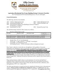
<strong>Elko</strong> <strong>County</strong><br />
Building & Safety Division<br />
540 Court St., Suite 104, <strong>Elko</strong>, Nevada 89801<br />
(775) 738-6816, Fax (775) 738-4581<br />
www.elkocountynv.net<br />
<strong>Residential</strong> <strong>Design</strong> <strong>Criteria</strong> & <strong>Checklist</strong><br />
One & Two Family Dwellings<br />
General Information:<br />
The following codes have been adopted:<br />
1997 Uniform Administrative Code 2003 Uniform Mechanical Code<br />
2003 International <strong>Residential</strong> Code (Building & Electrical Chapters) 2003 Uniform Plumbing Code<br />
2003 International Building Code (as referred by IRC) 2002 National Electrical Code (as referenced)<br />
The minimum design criteria for <strong>Elko</strong> <strong>County</strong> are as follows:<br />
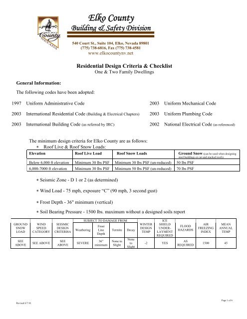
∗ Roof Live & Roof Snow Loads:<br />
Elevation Roof Live Load Roof Snow Loads Ground Snow (can be used when designing<br />
steel buildings or cut and stacked roofs)<br />
Below 6,000 ft elevation Minimum 30 lbs PSF Minimum 30 lbs PSF (un-reduced) 50 lbs PSF<br />
6,000-7000 ft elevation Minimum 30 lbs PSF Minimum 50 lbs PSF (un-reduced) 70 lbs PSF<br />
∗ Seismic Zone - D 1 or 2 (as determined)<br />
∗ Wind Load - 75 mph, exposure “C” (90 mph, 3 second gust)<br />
∗ Frost Depth - 36" minimum (vertical)<br />
∗ Soil Bearing Pressure - 1500 lbs. maximum without a designed soils report<br />
GROUND<br />
SNOW<br />
LOAD<br />
SEE<br />
ABOVE<br />
WIND<br />
SPEED<br />
CATEGORY<br />
SEE ABOVE<br />
SEISMIC<br />
DESIGN<br />
CRITERI8A<br />
SEE<br />
ABOVE<br />
Weathering<br />
SEVERE<br />
SUBJECT TO DAMAGE FROM<br />
Frost<br />
Line<br />
Depth<br />
36”<br />
minimum<br />
Termite<br />
None to<br />
Slight<br />
Decay<br />
None<br />
to<br />
Slight<br />
WINTER<br />
DESIGN<br />
TEMP<br />
ICE<br />
SHIELD<br />
UNDER-<br />
LAYMENT<br />
REQUIRED<br />
-2 YES<br />
FLOOD<br />
HAZARDS<br />
AS<br />
REQUIRED<br />
AIR<br />
FREEZING<br />
INDEX<br />
MEAN<br />
ANNUAL<br />
TEMP<br />
1500 45<br />
Revised 6/7/10<br />
Page 1 of 6
<strong>Elko</strong> <strong>County</strong>’s objective is to provide you, the applicant, with a guideline of necessary<br />
information to be submitted in order to ensure that your application is processed in a timely and<br />
professional manner. It is the responsibility of the contractor or owner-builder to become<br />
familiar and comply with the adopted codes, ordinances and the manufacturer’s requirements<br />
for the specific product and processes as approved by the ICC Evaluation Service as adopted<br />
by <strong>Elko</strong> <strong>County</strong>. This checklist is specific to the actual construction requirements to the structure<br />
itself. Other requirements for Zoning, FEMA or State Health are to be addressed also at the time<br />
of permit application. Additional construction information will be required when located within a<br />
flood zone.<br />
Plans and Specifications shall be drawn to scale (minimum 1/4" per foot) and shall be of<br />
sufficient clarity to indicate the location, nature and extent of the work proposed and show in<br />
detail that it will conform to the provisions of this code and all relevant laws, ordinances, rules<br />
and regulations, 1997 U.A.C., section 302.3<br />
The following information is required and must be submitted for the plan review of the proposed<br />
structure. Please provide two identical sets of plans for review. An “APPROVED” job copy<br />
will be returned to the applicant as required by U.A.C., section 303.1. The applicant must check<br />
each area below to indicate the documentation is provided as set forth in this checklist. When<br />
not applicable please indicate so by “N/A”.<br />
OR<br />
OR<br />
OR<br />
<strong>Design</strong> plans and supporting documents must be prepared, signed and stamped by a<br />
Nevada Registered Architect or Professional Engineer.<br />
<strong>Residential</strong> <strong>Design</strong>ers may submit design plans for single family or multifamily<br />
structures as authorized by NRS 623.330.<br />
Licensed Contractors may submit their own plans provided they are signed by the<br />
contractor and meet the conditions specified in NRS 623.330.<br />
Owner/Builders may prepare and submit their own plans for their own private residential<br />
use. Plans must be titled without reference to being prepared by a party other than the<br />
property owner who is building or overseeing the building activity. The plans must have<br />
the owner/builder’s original signature.<br />
The building construction plans prepared by a Nevada licensed design professional must be wet<br />
stamped with an original signature that states conditions are met.<br />
Plot Plan: (separate from the building plans)<br />
____ Accurate representation of the legal description - including property dimensions or<br />
acreage for large parcels over 40 acres<br />
____ Location all buildings and attached structures<br />
____ Show all setback distances to property lines from the proposed building and to other<br />
buildings within 20'<br />
____ Location of the main electrical service and electrical line, including wire size to the<br />
building with distances for possible voltage drop calculations for new electrical<br />
installations over 400 feet<br />
____ Location of applicable utilities: well, water lines, septic tank & lines, gas tank & lines,<br />
etc.<br />
____ Original signature of preparer<br />
Revised 6/7/10<br />
Page 2 of 6
Building Construction Plans:<br />
Cover Sheet<br />
____ <strong>Design</strong> <strong>Criteria</strong> list:<br />
a. Occupancy group<br />
b. Type construction of<br />
c. Seismic zone<br />
d. Square footage, total of all floors and accessory areas<br />
e. Height and number of stories<br />
f. Roof Snow/Live Load<br />
g. Wind Load<br />
h. Occupant load (Duplexes or Multi-Family)<br />
i. Code editions used<br />
____<br />
____<br />
____<br />
____<br />
____<br />
____<br />
Floor Plan:<br />
Building dimensions, including all room dimensions<br />
Room designation - (i.e.: living room, kitchen, bedroom, etc.)<br />
Light and ventilation per section R303, 2003 IRC<br />
Door and window sizes, designation of required egress windows, and required safety<br />
glazing<br />
Fire wall construction, fire rated door type (i.e.: metal or wood) and penetration rated<br />
materials - (for attached garages)<br />
Show crawlspace and attic access size and locations<br />
Footing Plan:<br />
____ Show Dimensions for continuous footings or pier pad footings (Table R403.1) including<br />
decks/porches<br />
____ Footing elevations that are stepped down due to changes in grade shall be shown on<br />
foundation plan<br />
____ Show depth below outside finished grade<br />
____ Show reinforcement iron size and spacing<br />
____ Show the Ufer ground size and location (if applicable)<br />
Foundation Wall Plan:<br />
____ Foundation wall height and thickness and PSI rating (Tables R404.1.1 & 402.2)<br />
____ Show reinforcement iron size and spacing (both vertical & horizontal), including any<br />
additional reinforcement iron as required by code at top of wall and around all window<br />
and door openings<br />
____ Anchor bolt & washer size, spacing and the embedded depth to comply with section<br />
____ Show underfloor ventilation method (in wall or rim) to comply with section R408, 2003<br />
IRC<br />
____ Show underfloor access size and location including access through any supporting walls<br />
Monolithic Foundation (if designed)<br />
Revised 6/7/10<br />
Page 3 of 6
____<br />
____<br />
____<br />
____<br />
____<br />
Show dimensions for the continuous footings (typically located at the top of the<br />
foundation)<br />
Show dimensions for the frost wall below the footings<br />
Show the depth below grade and foundation height above grade (6" minimum)<br />
Show reinforcement iron size and spacing (both vertical & horizontal)<br />
Foundation hold down devices shown when used with the alternate braced wall panels for<br />
the shear wall requirements as allowed by section R602.10.6, 2003 IRC or R602.10.6.2,<br />
2004 IRC Supplement<br />
____<br />
____<br />
Cross Sectional Plan:<br />
A complete cross sectional drawing detailing construction methods from the footing and<br />
foundation wall through the floor(s) and wall(s) to the roof structure shall be provided<br />
with full detail, including anchorage and all connections from foundation through roof<br />
structure and all changes in floor elevations. This applies to both the dwelling and<br />
garage; this will require two cross section plans.<br />
A complete stairway construction detail - (showing type of material, rise and run,<br />
headroom height, handrail, guardrail and direction of travel)<br />
Framing Plan:<br />
____ Conventional floor framing showing size of joists used, spans, spacing, bearing locations<br />
and hangers<br />
____ Engineered floor framing showing manufacturer’s series and size of joists used, spans,<br />
spacing, bearing locations, and hangers<br />
____ Exterior and interior shear wall bracing locations shown with method of shear panel, stud<br />
wall size and spacing<br />
____ Header sizes, spans and bearing to foundation for all specific locations (i.e.: doorways,<br />
windows, arch ways, overhead doors and covered porches/decks)<br />
____ Stairway construction details; rise and tread dimensions, vertical head clearance<br />
dimension, guard and handrail details<br />
____ Manufactured roof truss layout, spacing and slope(s) - showing uplift protection, bearing<br />
locations & girder truss placement and type of hangers Note: Must provide a separate<br />
roof sectional for multiple roof layouts.<br />
____ Engineered designed truss plans may be a deferred submittal; must be submitted at least<br />
one week prior to rough (four-way) inspection; original signature of design engineer<br />
required.<br />
____ Roof rafter framing layout - showing size, spacing, spans of members and roof slope(s).<br />
Show ridge beam size, bearing locations with method of connections and provide a<br />
separate roof sectional in multiple roof layouts, or when used on a truss roof for over<br />
framing. NOTE: Cut and stacked roofs shall be designed by a registered architect,<br />
residential designer or engineer prior to the plan submittal unless approved otherwise by<br />
the building official.<br />
____ Provide an analysis for bearing stud wall height greater than 10' and non-bearing stud<br />
wall greater than height listed in Table R602.3(5), 2003 I.R.C.<br />
____<br />
____<br />
Plumbing Plan: (shown on separate plan)<br />
Water heater location(s) and type of fuel source and BTU rating(s)<br />
Plumbing fixture locations and types - (sinks, toilets, lavs, tubs, showers, floor drains,<br />
water softeners)<br />
____ Plumbing diagrams for water, drain/waste and venting, gas piping and list the type of<br />
materials used and pipe size.<br />
Revised 6/7/10<br />
Page 4 of 6
Mechanical Plan: (shown on separate plan)<br />
____ FAU location(s) and size(s) (BTU rating) of furnace, boiler or equivalent and type of fuel<br />
source<br />
____ Fireplace location(s) - type of fuel source and BTU rating(s) (gas, oil, pellet, or wood)<br />
____ BTU rating for all fuel fired appliances, i.e.: ranges, ovens, clothes dryers, etc.<br />
____ Show combustion air complying with the requirements of Chapter 7 of the U.M.C.<br />
____ Exhaust fans<br />
____ Duct diagram showing size and type of materials used, ie: supply air, return air,<br />
combustion air and duct sizes.<br />
____ Flue sizes for all fuel fired appliances<br />
Electrical Plan: (shown on separate plan)<br />
____ Location of lights, fans, switches, receptacles and fixed appliances<br />
____ Location and amp ratings of all panels - (outside disconnect and load centers)<br />
____ List of all branch circuit schedule including circuit amperage size, wire size and type of<br />
materials.<br />
____ Location of smoke detectors (indicate wall or ceiling mount)<br />
____ Baseboard heating<br />
Elevation/Architectural Views:<br />
____ Exterior final grading elevations shown around the building (including finished floor<br />
elevations from grade for multiple stories - unless located in a flood zone)<br />
____ Exterior landings & steps showing type of material (concrete or wood), rise and run,<br />
handrail, guardrail<br />
____ Exterior deck (including roof covering) construction showing type of material, bearing<br />
location, with attachment connections, handrail and guardrails (if applicable)<br />
____ Exterior porch construction showing type of material, bearing location, with attachment<br />
connections<br />
____ Roof material type<br />
____ Exterior siding material - provide evaluation report for the types of exterior wall covering<br />
and supply all certificates of installation (if applicable)<br />
When the building official issues the permit where plans are required, the building official shall<br />
endorse in writing or stamp the plans and specifications APPROVED. Such approved plans and<br />
specifications shall not be changed, modified or altered without authorization from the building<br />
official, and all work regulated by this code shall be done in accordance with the approved plans.<br />
- Section 303.1, 1997 U.A.C. Additional plan review fees will apply to changed, modified or<br />
altered plans.<br />
All construction or work for which a permit is required shall be subject to inspection by the<br />
building official and all such construction or work shall remain accessible and exposed. - Section<br />
305.1, 1997 U.A.C.<br />
Work requiring a permit shall not be commenced until the permit holder or an agent of the<br />
permit holder shall have posted or otherwise made available an inspection record card as to allow<br />
the building official to conveniently make the required entries thereon regarding inspections of<br />
the work - Section 305.2, 1997 U.A.C. (NOTE: Failure to post permit documents shall be<br />
subject to re-inspection fees.)<br />
Revised 6/7/10<br />
Page 5 of 6
It shall be the duty of the person doing the work authorized by a permit to notify the building<br />
official that such work is ready for inspection - Section 305.3, 1997 U.A.C. <strong>Elko</strong> <strong>County</strong><br />
requires all inspection requests to be scheduled 24 hours in advance by 4:00 pm. Inspections will<br />
be done the following working day between 8:00 am - 5:00 pm.<br />
Applications for which no permit is issued within 180 days following the date of application<br />
shall expire by limitation, and plans and other data submitted for review may thereafter be<br />
returned to the applicant or destroyed by the building official – Section 304.4, 1997 U.A.C.<br />
Every permit issued by the building official under the provisions of this code shall expire by<br />
limitation and become null and void if the building or work authorized by such permit is not<br />
commenced within 180 days from the date of such permit, or if the building or work authorized<br />
by such permit is suspended or abandoned at any time after the work is commenced for a period<br />
of 180 days - Section 303.4, 1997 U.A.C.<br />
I, _________________________________ do hereby verify that all necessary and required<br />
information has been submitted for plan review on this date of ______________________,<br />
20___.<br />
Revised 6/7/10<br />
Page 6 of 6