Cylinders - Lifco Hydraulics USA
Cylinders - Lifco Hydraulics USA
Cylinders - Lifco Hydraulics USA
Create successful ePaper yourself
Turn your PDF publications into a flip-book with our unique Google optimized e-Paper software.
ZJ+Stroke<br />
G<br />
BB<br />
DD<br />
Thds.<br />
J<br />
ZJ+Stroke<br />
DD<br />
Thds.<br />
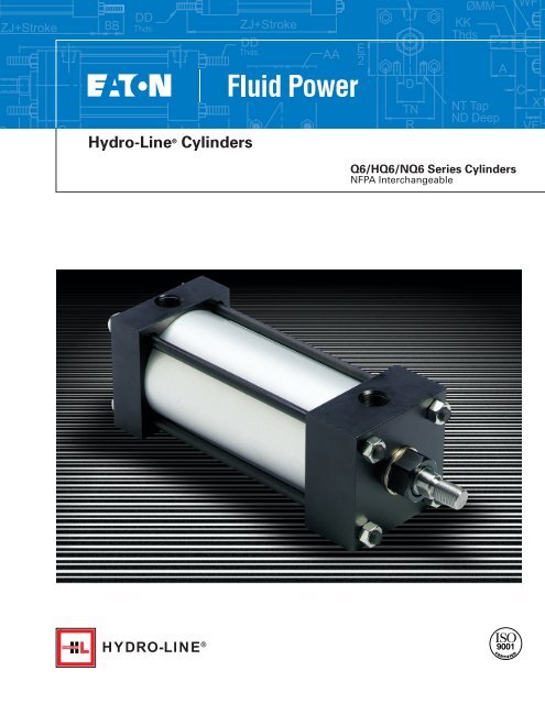
Hydro-Line ® <strong>Cylinders</strong><br />
AA<br />
E<br />
2<br />
D<br />
TN<br />
R<br />
ØMM<br />
KK<br />
Thds<br />
NT Tap<br />
ND Deep<br />
A<br />
WF<br />
C<br />
XT<br />
VF<br />
Q6/HQ6/NQ6 Series <strong>Cylinders</strong><br />
NFPA Interchangeable<br />
HYDRO-LINE ®
Q6 Design Features<br />
L<br />
E<br />
K<br />
F<br />
J<br />
D<br />
G<br />
H<br />
I<br />
C<br />
B<br />
A<br />
M<br />
A<br />
B<br />
C<br />
D<br />
E<br />
Rod Bearing.<br />
Externally removable threaded<br />
steel bearing cartridge with black<br />
oxide finish in Series Q6/HQ6, or<br />
stainless steel for Series NQ6<br />
option, both with an oil-impregnated<br />
sintered iron rod bearing.<br />
Rod Seal.<br />
Nitrile lip-type seal is pressure<br />
energized and wear compensating<br />
for durability and long life.<br />
Wiper Seal.<br />
Urethane wiper seal keeps<br />
contaminates from getting into<br />
cylinder by aggressively wiping<br />
foreign materials from the piston<br />
rod, enhancing the rod seal life.<br />
Tubing.<br />
High-strength aluminum tubing is<br />
clear anodized on the O.D. and<br />
hard anodic coated on the I.D.,<br />
resulting in a smooth, file hard<br />
(60RC), corrosion and score<br />
resistant surface finish for<br />
extended seal life in Series<br />
Q6/HQ6. Stainless steel tubing is<br />
used in Series NQ6 option.<br />
Piston Seals.<br />
Long-wearing nitrile cup seals.<br />
G<br />
H<br />
I<br />
Cushion Seals.<br />
Advanced design features a<br />
unique, one-piece, compound<br />
seal of nitrile* captured within<br />
a precision machined groove.<br />
Linear and radial "float" of<br />
the cushion seals eliminates<br />
misalignment. Super Cushions<br />
provide exceptionally fast "out of<br />
cushion" stroke reversal. (Head<br />
and Cap Cushions are optional on<br />
1-1/2 thru 8 inch bore cylinders.)<br />
*Nitrile seals on the 5/8" & 1" rod<br />
diameter. For rod sizes 1-3/8"<br />
and larger, urethane seals are<br />
standard.<br />
Adjustable Captive Cushion<br />
Adjusting Screw.<br />
One-piece stainless steel cushion<br />
screw with fine threads is held<br />
captive by a stainless steel press-in<br />
retaining washer. This allows for<br />
safe and precise adjustment of<br />
the cushion without inadvertent<br />
removal. (Optional - Not Shown)<br />
Head/ Cap.<br />
Precision machined from alloy<br />
aluminum, then black anodized<br />
for corrosion resistance in Series<br />
Q6/HQ6, and electroless nickel<br />
plated for Series NQ6 option.<br />
K<br />
L<br />
M<br />
Pistons.<br />
Machined solid aluminum alloy,<br />
light-weight for low inertia, yet<br />
strong. (Threaded and installed<br />
with high strength threadlocker<br />
adhesive.)<br />
Wear Ring.<br />
Reinforced Teflon® compounded<br />
with polyphenylene sulfide<br />
provides supreme wear and<br />
excellent bearing support.<br />
Piston Rod.<br />
Hard chrome plated high-tensile<br />
carbon steel, ground and polished<br />
in Series Q6/HQ6, and<br />
stainless steel for Series NQ6<br />
option.<br />
F<br />
O-Ring Body Seal.<br />
Nitrile material is standard, with<br />
Viton® optional.<br />
J<br />
Tie Rods.<br />
High-strength steel in Series<br />
Q6/HQ6, and stainless steel for<br />
Series NQ6 option, maintains<br />
uniform compression on body<br />
end seals.<br />
Teflon® and Viton® are registered trademarks<br />
of E.I. Dupont Company.<br />
2
Table Of Contents<br />
Q6 Design Features...........................................................page 2<br />
Q6 Options........................................................................ page 3<br />
Port and Cushion Adjustment Locations............................page 3<br />
Port Sizes ..........................................................................page 3<br />
How to Order a Q6 Cylinder ..............................................page 4<br />
Hydro-Line <strong>Cylinders</strong> Application Data Sheet....................page 5<br />
Q6 Mounting Dimension Drawings .................................page 6-8<br />
Q6 3/4˝ and 1-1/8˝ Mounting Dimension Drawings ......page 9-10<br />
Q6T Series Air/Oil Tanks ..................................................page 11<br />
Q6 Options<br />
• Cushions<br />
• Oversized rod<br />
• Oversized NPTF and<br />
SAE ports<br />
• Stainless steel rod<br />
• Stop tube<br />
• Rod scraper<br />
• Fiberglass Tube<br />
• High temperature seals<br />
• Air/oil piston<br />
Q6 Special Modifications<br />
• Special Seals<br />
• Nonstd. mount<br />
• Oversize ports<br />
• Bronze bushings<br />
• Stainless steel rod<br />
• Stop tube<br />
• Nonrotating rod<br />
• Rod boots<br />
• Indicator switches<br />
• Double rod end<br />
• Rod boots<br />
• Nonrotating rod<br />
• Electroless nickel plated<br />
• Spring extend/return<br />
• Piston with magnetic ring<br />
• Rod end couplers<br />
• Studded rod ends<br />
• Hardened rods<br />
• Adjustable Stroke<br />
• Studded rod<br />
• Port or cushion modifications<br />
• Double-end rod with different<br />
rod ends<br />
• Special paint/plating<br />
• Linear displacement transducer<br />
• Adjustable stroke<br />
• Spring extend/return<br />
• Hardened rod<br />
Cylinder Mounting Accessories ..................................page 12-14<br />
Accessories for 3/4˝ and 1-1/8˝ Bore <strong>Cylinders</strong> ...............page 15<br />
Technical Data .................................................................page 16<br />
Low Profile Reed and Hall Effect Switches.................page 17-18<br />
Switch Specifications .......................................................page 19<br />
Rod End Styles ................................................................page 20<br />
Oversized Rod Information ..............................................page 21<br />
3/4˝ and 1-1/8˝ Bore Cylinder Dimensions.......................page 21<br />
Cylinder Dimensions...................................................page 22-23<br />
Port and Cushion Adjustment Locations<br />
Standard port locations are at No. 1,<br />
with optional locations at No. 2, 3 or 4.<br />
Standard cushion adjustment location is<br />
in location No. 2 (code C), with optional<br />
locations at C1, C3 or C4.<br />
Port Sizes<br />
Bore Undersize Standard SAE<br />
1 1 ⁄2, 2, 2 1 ⁄2<br />
1<br />
⁄4 NPTF 3<br />
⁄8 NPTF #6<br />
3 1 ⁄4, 4, 5 3<br />
⁄8 NPTF 1<br />
⁄2 NPTF #10<br />
6, 7, 8 1<br />
⁄2 NPTF 3<br />
⁄4 NPTF #12<br />
EXCEPTIONS:<br />
• Ports at No. 3 not available on E mount cap on 1 1 ⁄2" through<br />
3 1 ⁄4" bores.<br />
• Ports at No. 3 on B mount head and cap not available on 1 1 ⁄2"<br />
and 2" bores.<br />
• Standard NPTF and SAE ports at No. 3 on B mount head and<br />
cap not available on 3 1 ⁄4" bores.<br />
• Head cushion not available on 1 1 ⁄2" bore with 1" diameter rod.<br />
Specifications<br />
Bore sizes: w˝ through 8˝<br />
Pressure rating: 250 PSI air, 400 PSI hydraulic<br />
Temperature: -20°F to 400°F optional<br />
NFPA interchangeable mountings<br />
Q6: Pneumatic cylinders incorporate internally lubricated<br />
nitrile lip type piston and rod seals, which are permanently<br />
lubricated at assembly by filling the “v” groove with<br />
molybdenum disulfide grease.<br />
O-Ring Tube End Seals<br />
O-ring tube end seals in nitrile material are<br />
pressure compensating and reusable.<br />
Cushion Seals<br />
INTO CUSHION<br />
OUT OF CUSHION<br />
As the cylinder enters cushion, the new<br />
floating elastomeric cushion seal aligns itself<br />
on the cushion spear or collar. Sealing takes<br />
place on the spear or collar diameter and the<br />
back of the cushion seal pocket. Air trapped<br />
between the cushion and piston seal is<br />
metered out past the cushion adjustment<br />
needle to create the desired cushioning<br />
effect, dependent upon cylinder speed and<br />
load. As the cylinder comes out of cushion the<br />
cushion seal is unseated from the back of the<br />
pocket. Molded feet on the front face of the<br />
seal do not allow it to seal on the front of the<br />
pocket. Depressions molded into the outer<br />
diameter allow air to escape around the seal<br />
and work on the entire piston face for a quick<br />
break-away and stroke reversal. Due to this<br />
“self-checking” design, there is no need for<br />
ball checks.<br />
3
4<br />
How to Order a Q6 Cylinder<br />
Feature Description Symbol<br />
Rod Diameter Specify in inches (2 position decimal) —<br />
Noncushioned<br />
N<br />
Cushioned cap end, location 1<br />
C1<br />
Cushioned cap end, location 2<br />
C<br />
Cushioned cap end, location 3<br />
C3<br />
Cushioned cap end, location 4<br />
C4<br />
Cushioned head end, location 1<br />
H1<br />
Cushioned head end, location 2<br />
H<br />
Cushioned head end, location 3<br />
H3<br />
Cushions Cushioned head end, location 4<br />
H4<br />
Cushioned both ends, location 1<br />
B1<br />
Cushioned both ends, location 2<br />
B<br />
Cushioned both ends, locations head 2, cap 3 H2C3<br />
Cushioned both ends, locations head 2, cap 4 H2C4<br />
Cushioned both ends, locations head 3, cap 2 H3C2<br />
Cushioned both ends, location 3<br />
B3<br />
Cushioned both ends, locations head 3, cap 4 H3C4<br />
Cushioned both ends, location 4<br />
B4<br />
Stroke Specify in inches (2 position decimal) —<br />
Bore Specify in inches (2 position decimal) —<br />
Double Rod Include ONLY for double-rod cylinder D<br />
Side lugs, MS2<br />
A<br />
Side tapped, MS4<br />
B<br />
Cap fixed clevis, MP1<br />
C<br />
Cap Mono clevis<br />
CM<br />
Cap detachable clevis, MP2<br />
DC<br />
Cap Mono detachable clevis, MP4<br />
DCM<br />
End lugs, MS7<br />
E<br />
Head rectangular flange, MF1<br />
F<br />
Head square, ME5<br />
G<br />
Head square flange, MF5<br />
J<br />
No mount<br />
K<br />
All tie rods extended, MX1<br />
L<br />
Mounting<br />
Head end tie rods extended, MX3<br />
M<br />
Style<br />
Cap end tie rods extended, MX2<br />
N<br />
Cap square, ME6<br />
P<br />
Cap rectangular flange, MF2<br />
R<br />
Cap square flange, MF6<br />
S<br />
Intermediate fixed trunnion, MT4<br />
TT<br />
Head trunnion, MT1<br />
U<br />
Cap trunnion, MT2<br />
W<br />
End angles, MS1<br />
Y<br />
Bolt through, MS8 ( 3 /4˝ - 1 1 /8˝ bores)<br />
A<br />
Tapped Face, MR1 ( 3 /4˝ - 1 1 /8˝ bores)<br />
FM<br />
Sleeve nut for tapped face (1 1 /2 - 8˝ bores) FM<br />
Threaded nose, MNR1<br />
TN<br />
Air prelubricated to 250 psi<br />
Q6<br />
Model/Series<br />
Hydraulic to 400 psi<br />
HQ6<br />
Air/oil tank (aluminum caps/fiberglass tube) Q6T<br />
Corrosion Resistant Air to 250 psi<br />
NQ6<br />
Male, large 1<br />
Male, large, extended<br />
1X<br />
Male, small (standard) 2<br />
Male, small, extended<br />
2X<br />
◆ Male modified<br />
2M<br />
Rod End<br />
Female 4<br />
Style<br />
◆ Female modified<br />
4M<br />
Plain end 5<br />
Male, full rod diameter 6<br />
Male, for rod end coupling 10<br />
Modified<br />
M<br />
NPTF<br />
N<br />
Ports NPTF, 1st size over standard<br />
L<br />
SAE<br />
S<br />
Nitrile lip type<br />
N<br />
Nitrile ELF rounded lip type<br />
L<br />
Polypak<br />
P<br />
Rod Seals<br />
Urethane Ultra Seal<br />
H<br />
Viton lip type<br />
V<br />
Nitrile lip type with scraper<br />
S<br />
Viton lip type with scraper<br />
U<br />
Special<br />
X<br />
Nitrile lip-type & Teflon wear ring<br />
N<br />
Nitrile lip type & Teflon wear ring with:<br />
- Magnetic piston (2 switches) Hall Effect F<br />
- Magnetic piston (1 switch) Hall Effect G<br />
Piston Seals - Magnetic piston (2 switches) Reed M<br />
- Magnetic piston (1 switch) Reed O<br />
- Magnetic piston (no switch) H<br />
Viton lip-type<br />
V<br />
Special<br />
X<br />
Head End 1 thru 4<br />
Port Special<br />
X<br />
Locations Cap End 1 thru 5<br />
Special<br />
X<br />
Special Include ONLY if special modifications<br />
X<br />
Modifications are required. (SEE PAGE 3 FOR LIST)<br />
◆ Include drawing or description<br />
Q6KD - 3.25 X 8 - N - 1.38<br />
- 2 - N - N - N - 1 - 1 - X<br />
Hydro-Line standard<br />
cylinders can be<br />
completely and<br />
accurately identified<br />
with a model number<br />
that encodes construction<br />
specifications. To<br />
develop the model<br />
number for ordering<br />
a cylinder, see the<br />
example on this page.<br />
HOW TO ORDER<br />
1. Quantity<br />
2. Model Number<br />
3. Special<br />
modifications<br />
if required<br />
4. Operating<br />
temperature<br />
if below -40°F<br />
or above 200°F<br />
5. Required<br />
ship date<br />
HYDRO-LINE ®<br />
Q6KD-3.25X8-N-1.38-<br />
2-N-N-N-1-1-X<br />
194011234-1<br />
A1579-375<br />
Customer Number<br />
(if desired)<br />
Hydro-Line Serial Number<br />
PORT LOCATIONS<br />
Port location 5 is on the<br />
center of the back face<br />
of the cap end.
Hydro-Line <strong>Cylinders</strong> Application Data Sheet<br />
Company Name:<br />
Distributor Name:<br />
Contact:<br />
Contact:<br />
Phone Number:<br />
Fax Number:<br />
Phone Number:<br />
Fax Number: ______________<br />
QUANTITY<br />
Model Numbering System<br />
SEALS PORT LOC<br />
MODEL/SERIES MOUNT BORE STROKE CUSHION ROD DIA ROD STY PORTS ROD PSTN H C MODEL<br />
• • •<br />
DOUBLE END ADDITIONAL NEEDLE BRONZE DRAIN- IND. MODEL<br />
ROD STYLE ROD LENGTH LOCATION KEYPLATE 4-FLAT BLEEDERS BUSHING BACK SWITCH PREFIX<br />
C<br />
C<br />
HEAD CAP HEAD CAP HEAD CAP<br />
Stop Tube Length Trunnion XI Dimension Stainless Steel Rod Type<br />
Please fill in all available information above. Refer to the Hydro-Line Model Numbering System on Pages 2.<br />
WHAT IS THE OPERATING ENVIRONMENT?<br />
Fluid Media Operating Pressure Temperature at Cylinder<br />
Air Minimum psi Minimum °F<br />
Oil Typical psi Typical °F<br />
Other Maximum psi Maximum °F<br />
Fluid Type<br />
WHAT IS THE WORK BEING PERFORMED?<br />
Load Rod Speed Cycles per Minute<br />
Push lbs. Extend in./sec.<br />
Pull lbs. Retract in./sec. (in and out)<br />
WHAT IS THE MOUNTING?<br />
Attitude Rod End Connection Known Side Load<br />
Vertical Angle Horizontal Firmly Guided<br />
Degrees From Vertical Supported lbs.<br />
Rod Up Rod Up Unsupported<br />
Rod Down<br />
Rod Down<br />
WHAT ENVIRONMENTAL CONDITIONS IS THE CYLINDER SUBJECTED TO?<br />
Standard Factory Corrosive Washdown Chemical? Outdoors Other<br />
WHAT IS THE PRESENT CYLINDER TYPE AND MODEL NUMBER?<br />
WHAT IS THE PRESENT PROBLEM?<br />
WHAT INDUSTRY IS THE CYLINDER WHAT TYPE OF MACHINE IS THE WHAT IS THE APPLICATION?<br />
USED IN?<br />
CYLINDER USED ON?<br />
APPLICATION SKETCH:<br />
DESCRIPTION OF APPLICATION<br />
OR SPECIAL REQUIREMENT:<br />
PREPARED BY: DATE: REVIEWED BY: DATE:<br />
CUSTOMER DRAWING NUMBER: REVISION DATES: HYDRO-LINE QUOTE NUMBER:<br />
FRM-24-011, 8/01<br />
5
Q6 Mounting Dimensions<br />
See Cylinder Dimensions on Page 22-23<br />
EE<br />
NPT (2)<br />
ØSB<br />
E<br />
R<br />
ØB<br />
Bushing<br />
ØMM<br />
KK<br />
Thds<br />
WF<br />
Y<br />
P+Stroke<br />
EE<br />
NPT (2)<br />
ØB<br />
Bushing<br />
ØMM<br />
KK<br />
Thds<br />
Y<br />
WF<br />
P+Stroke<br />
SH ST<br />
D<br />
(Flats)<br />
TS<br />
US<br />
E<br />
2 A<br />
C<br />
SW<br />
VF<br />
XS<br />
G<br />
SU<br />
J<br />
LB+Stroke SJ<br />
SS+Stroke<br />
ZB+Stroke<br />
K<br />
SW<br />
E<br />
2<br />
D<br />
TN<br />
R<br />
E<br />
A<br />
NT Tap<br />
ND Deep<br />
C<br />
G<br />
XT<br />
VF<br />
SN+Stroke<br />
LB+Stroke<br />
ZB+Stroke<br />
J<br />
K<br />
Q6A – Side Lugs Mount (NFPA Style MS2)<br />
Q6B – Side Tapped Mount (NFPA Style MS4)<br />
EE<br />
NPT (2)<br />
ØEB<br />
Hole (4)<br />
E<br />
2 ET<br />
D<br />
(Flats)<br />
R<br />
E<br />
ØB<br />
Bushing<br />
ØMM<br />
KK<br />
Thds<br />
C<br />
Y<br />
WF<br />
VF<br />
EF<br />
XE+STROKE<br />
P+Stroke<br />
G<br />
LB+Stroke<br />
ZE+Stroke<br />
SE+Stroke<br />
J<br />
EL<br />
EO<br />
AH<br />
EE<br />
NPT (2)<br />
E<br />
R<br />
D<br />
(Flats)<br />
S<br />
ØB<br />
Bushing<br />
ØMM<br />
KK<br />
Thds<br />
ØAB<br />
Y<br />
WF<br />
A<br />
C<br />
VF<br />
NF<br />
G<br />
XA+STROKE<br />
P+Stroke<br />
LB+Stroke<br />
SA+Stroke<br />
J<br />
K<br />
AL<br />
AT<br />
AO<br />
For double rod end cylinder (Mount ED), add 1/2˝ plus FH dimension to<br />
mounting dimensions SE, ZE and XE.<br />
Note: Bottoms of heads and caps are mounting surfaces.<br />
Lugs hold cylinders against mounting surface.<br />
Note: 8˝ bore does not use full front plate.<br />
Use F in place of FH. Use V in place of VB.<br />
Q6E – End Lugs Mount (NFPA Style MS7)<br />
For double rod end cylinder (Mount YD), add 1/2˝ plus FH dimension to<br />
mounting dimensions SA and XA.<br />
Note: 8˝ bore does not use full front plate. Use F in place of FH.<br />
Use V in place of VB. AL measured from head.<br />
Q6Y – End Angles Mount (NFPA Style MS1)<br />
EE<br />
NPT (2)<br />
ØB<br />
Bushing<br />
ØMM<br />
KK<br />
Thds<br />
Y<br />
WF<br />
P+Stroke<br />
ØB<br />
Bushing<br />
EE<br />
NPT (2) ØMM<br />
KK<br />
Thds<br />
Y<br />
WF<br />
P+Stroke<br />
Y+Stroke<br />
ØB<br />
Bushing<br />
ØMM<br />
KK<br />
Thds<br />
D<br />
(Flats)<br />
R<br />
E<br />
A<br />
C<br />
VF<br />
G<br />
LB+Stroke<br />
ZB+Stroke<br />
J<br />
K<br />
D<br />
(Flats)<br />
R<br />
E<br />
A<br />
C<br />
VF<br />
G<br />
LD+Stroke<br />
G<br />
ZL+Stroke<br />
ZM + 2x Stroke<br />
C+Stroke<br />
K<br />
A<br />
Add D for double end after the desired series and mounting style.<br />
Example: Q6KD.<br />
Q6K – No Mount<br />
Q6D – Double Rod<br />
6
Q6 Mounting Dimensions<br />
See Cylinder Dimensions on Page 22-23<br />
Supplied with<br />
ØB<br />
Standard Pin<br />
Bushing<br />
Y P+Stroke<br />
EE NPT (2)<br />
ØMM<br />
WF<br />
LR<br />
KK<br />
ØCD<br />
Thds<br />
MR<br />
A<br />
G<br />
J<br />
C CW CW<br />
VF LB+Stroke K M CB<br />
L<br />
XC+Stroke<br />
E<br />
ØB<br />
Bushing<br />
ØMM<br />
KK<br />
Thds<br />
A<br />
C<br />
Y<br />
WF<br />
G<br />
VF<br />
P+Stroke<br />
XD+Stroke<br />
J<br />
EE NPT (2)<br />
LR<br />
ØCD<br />
L<br />
FL M<br />
MR<br />
CW<br />
Supplied with<br />
Standard Pin<br />
CB<br />
E<br />
CW<br />
Q6C – Cap Clevis Mount (NFPA Style MP1)<br />
Q6DC – Cap Detachable Clevis Mount (NFPA Style MP2)<br />
UV øTD<br />
EE<br />
NPT (2)<br />
TL<br />
E<br />
R<br />
D<br />
(Flats)<br />
TM<br />
UM<br />
TL<br />
øB<br />
Bushing<br />
øMM<br />
KK<br />
Thds<br />
A<br />
Customer<br />
Must<br />
Specify<br />
XI<br />
WF<br />
C<br />
VF<br />
Y P + Stroke<br />
G<br />
XI (Min.)<br />
BD J<br />
LB + Stroke<br />
ZB + Stroke<br />
K<br />
ØB<br />
Bushing<br />
ØMM<br />
KK<br />
Thds<br />
A<br />
C<br />
WF<br />
Y<br />
VF<br />
G<br />
P+Stroke<br />
XD+Stroke<br />
J<br />
LR<br />
ØCD<br />
MR<br />
L<br />
FL M<br />
CB<br />
E<br />
Q6TT – Intermediate Fixed Trunnion Mount (NFPA Style MT4)<br />
Q6DCM – Cap Detachable Mono Clevis Mount<br />
(NFPA Style MP4)<br />
EE NPT (2)<br />
ØTD<br />
TL<br />
D<br />
(Flats)<br />
R<br />
E<br />
UT<br />
ØB<br />
Bushing<br />
ØMM<br />
KK<br />
Thds<br />
TL<br />
A<br />
C<br />
Y<br />
WF<br />
G<br />
VF<br />
XG<br />
P+Stroke<br />
LB+Stroke<br />
ZB+Stroke<br />
J<br />
K<br />
ØB<br />
Bushing<br />
ØMM<br />
KK<br />
Thds<br />
A<br />
C<br />
Y<br />
WF<br />
G<br />
VF<br />
P+Stroke<br />
LB+Stroke<br />
XJ+Stroke<br />
ZB+Stroke<br />
J<br />
EE NPT (2)<br />
K<br />
TL<br />
R<br />
E<br />
UT<br />
TL<br />
ØTD<br />
Q6U – Head Trunnion Mount (NFPA Style MT1)<br />
Q6W – Cap Trunnion Mount (NFPA Style MT2)<br />
7
Q6 Mounting Dimensions<br />
See Cylinder Dimensions on Page 22-23<br />
ØB<br />
Bushing<br />
ØMM<br />
KK<br />
Thds<br />
A<br />
Y<br />
WF<br />
C<br />
VF<br />
G<br />
P+Stroke<br />
LB+Stroke<br />
ZF+Stroke<br />
J<br />
F<br />
FB<br />
Holes (4)<br />
E R<br />
EE NPT (2)<br />
TF<br />
UF<br />
EE NPT (2)<br />
FB Holes (8)<br />
UF TF<br />
D<br />
(Flats)<br />
R<br />
E<br />
øB<br />
Bushing<br />
øMM<br />
KK<br />
Thds<br />
A<br />
Y<br />
WF<br />
C G<br />
V<br />
W<br />
F<br />
P + Stroke<br />
LB + Stroke<br />
ZB + Stroke<br />
Note: Tie rod nuts will extend past the head or cap.<br />
K thickness on the end opposite flange mounting.<br />
J<br />
K<br />
Q6J – Head Square Flange Mount (NFPA Style MF5) (1 1 ⁄2˝-6˝ Bores)<br />
Q6R – Cap Rectangular Flange Mount (NFPA Style MF2)<br />
MX2<br />
BB<br />
FH<br />
MX3<br />
( 3 ⁄4˝-6˝ Bores)<br />
øB<br />
Bushing<br />
øMM<br />
KK<br />
Thds<br />
Y<br />
WF<br />
XF + Stroke<br />
P + Stroke<br />
EE NPT (2)<br />
FB Holes (8)<br />
TF UF<br />
EE<br />
NPT (2)<br />
ZJ+Stroke<br />
BB<br />
Y<br />
DD<br />
Thds.<br />
BB DD<br />
Thds.<br />
P+Stroke MX1<br />
ZJ+Stroke<br />
DD<br />
Thds.<br />
AA<br />
A<br />
C<br />
VF<br />
G<br />
LB + Stroke<br />
ZF + Stroke<br />
J<br />
F<br />
R<br />
E<br />
Q6S – Cap Square Flange Mount (NFPA Style MF6)<br />
(1 1 ⁄2˝-6˝ Bores)<br />
D<br />
(Flats)<br />
RE<br />
Esq<br />
C<br />
G<br />
V<br />
FH<br />
LB+Stroke<br />
ZJ+Stroke<br />
(MX1) L – Both tie rods extended<br />
(MX2) N – Cap end tie rods extended)<br />
(MX3) M – Head end tie rods extended<br />
J<br />
BB<br />
RE<br />
ØB<br />
Bushing<br />
ØMM<br />
KK<br />
Thds<br />
Y<br />
P+Stroke<br />
EE NPT (2)<br />
EB<br />
Holes (4)<br />
Q6L, M, N – Tie Rods Extended Mount<br />
(NFPA Style MX1, MX2, MX3)<br />
A<br />
C<br />
VF<br />
G<br />
LB+Stroke<br />
ZJ+Stroke<br />
J<br />
R<br />
TE<br />
E<br />
EE NPT (2)<br />
EB<br />
Holes (4)<br />
E<br />
2<br />
D<br />
(Flats)<br />
R<br />
TE<br />
E<br />
ØB<br />
Bushing<br />
ØMM<br />
KK<br />
Thds<br />
A<br />
C<br />
Y<br />
VF<br />
G<br />
P+Stroke<br />
LB+Stroke<br />
ZB+Stroke<br />
J<br />
K<br />
Q6P – Cap Square Mount (NFPA Style ME4)<br />
EE NPT (2)<br />
DD Thds.<br />
4 Places<br />
Both Ends<br />
D<br />
(Flats)<br />
TN<br />
R<br />
E<br />
ØB<br />
Bushing<br />
ØMM<br />
KK<br />
Thds<br />
AA<br />
NT Tap<br />
ND Depth<br />
A<br />
Y<br />
WF<br />
C<br />
G<br />
VF<br />
XT<br />
(7˝ & 8˝ Bores only)<br />
P+Stroke<br />
LB+Stroke<br />
SN+Stroke<br />
ZJ+Stroke<br />
J<br />
Q6G – Head Square Mount (NFPA Style ME3)<br />
(7˝ & 8˝ Bores only)<br />
Q6FM – Sleeve Nut for Tapped Face Mounts<br />
(1 1 ⁄2˝-6˝ Bores)<br />
8
Q6 3 ⁄4˝ - 1 1 ⁄8˝ Mounting Dimensions<br />
See Cylinder Dimensions on Page 21<br />
ØDB Hole Thru<br />
ØTB C'Bore for<br />
SB Screws 3 Places<br />
CC<br />
Thds.<br />
ØMM<br />
XB<br />
H<br />
P+Stroke<br />
K<br />
EE<br />
NPT (2)<br />
ØMM<br />
CC<br />
Thds.<br />
Y<br />
P+Stroke<br />
D<br />
(Flats)<br />
ØRM<br />
E sq<br />
DN<br />
A<br />
C<br />
V<br />
G<br />
LB+Stroke<br />
ZB+Stroke<br />
J<br />
D<br />
(Flats)<br />
TN<br />
ØRM<br />
E sq<br />
NT Tap<br />
TK Depth<br />
A<br />
XT<br />
V<br />
C<br />
G<br />
SN+Stroke<br />
LB+Stroke<br />
ZB+Stroke<br />
Note: Two mounting holes in head,<br />
one hole in cap.<br />
J<br />
Q6A – Bolt Through Mounts (ANSI MS8) Q6B – Tapped Mounts<br />
(ANSI MS9)<br />
EE<br />
NPT (2)<br />
FB<br />
Holes (4)<br />
E R<br />
ØMM<br />
CC<br />
Thds.<br />
P+Stroke<br />
ØMM<br />
CC<br />
Thds.<br />
Y<br />
P+Stroke<br />
EE<br />
NPT (2)<br />
FB<br />
Holes (4)<br />
E R<br />
D<br />
(Flats)<br />
TF<br />
UF<br />
A<br />
W<br />
G<br />
FH<br />
LB+Stroke<br />
ZB+Stroke<br />
J<br />
A<br />
C<br />
V<br />
G<br />
LB+Stroke<br />
ZF+Stroke<br />
J<br />
FH<br />
TF<br />
UF<br />
Q6F – Head Rectangular Flange Mounts<br />
(ANSI MF1)<br />
Q6R – Cap Rectangular Flange Mounts<br />
(ANSI MF2)<br />
E sq<br />
EE<br />
NPT (2)<br />
ØMM<br />
CC<br />
Thds.<br />
Y<br />
P+Stroke<br />
EE<br />
NPT (2)<br />
KM Thds.<br />
ØMM<br />
CC<br />
Thds.<br />
P+Stroke<br />
D<br />
(Flats)<br />
ØRM<br />
RE<br />
RT Thds.<br />
on BC Bolts<br />
Circle<br />
4 Places<br />
A<br />
C<br />
V<br />
G<br />
LB+Stroke<br />
ZB+Stroke<br />
J<br />
D<br />
(Flats)<br />
E sq<br />
A<br />
V<br />
C<br />
TL<br />
XN<br />
F<br />
ZB+Stroke<br />
J<br />
Q6FM – Head Tapped Face Mounts<br />
(ANSI MR1)<br />
Q6TN – Threaded Nose Mounts<br />
(ANSI MNR1)<br />
9
Q6 3 ⁄4˝ - 1 1 ⁄8˝ Mounting Dimensions<br />
See Cylinder Dimensions on Page 21<br />
EE<br />
NPT (2)<br />
ØMM<br />
CC<br />
Thds.<br />
Y<br />
P+Stroke<br />
ØMM<br />
CC<br />
Thds.<br />
Y<br />
P+Stroke<br />
EE NPT (2)<br />
ØDB Hole Thru<br />
ØTB C'Bore<br />
DN for SB<br />
Screws<br />
4 Places<br />
D<br />
(Flats)<br />
ØRM<br />
E sq<br />
A<br />
C<br />
V<br />
G<br />
LB+Stroke<br />
ZB+Stroke<br />
J<br />
A<br />
C<br />
V<br />
XG<br />
G<br />
H<br />
J<br />
G<br />
SN+Stroke<br />
LB+Stroke<br />
ZB+Stroke<br />
K<br />
D<br />
(Flats)<br />
ØRM<br />
E sq<br />
TS<br />
US<br />
ST<br />
Q6K– No Mounts<br />
(ANSI MX6)<br />
Q6AD – Double Rod Bolt Through Mounts<br />
ØMM<br />
CC<br />
Thds.<br />
Y<br />
P+Stroke<br />
ØCD<br />
EE<br />
NPT (2)<br />
ØMM<br />
CC<br />
Thds.<br />
Y<br />
P+Stroke<br />
ØCD<br />
EE<br />
NPT (2)<br />
A<br />
C<br />
V<br />
G<br />
J L<br />
M<br />
CB<br />
LB+Stroke<br />
E<br />
XC+Stroke<br />
sq<br />
A<br />
C<br />
V<br />
G<br />
M<br />
J L<br />
LB+Stroke FL CW<br />
CB<br />
XD+Stroke<br />
E sq<br />
CW<br />
Q6CM – Fixed Eye Mounts<br />
(ANSI MP3)<br />
Q6DC – Detachable Clevis Mounts<br />
(ANSI MP2)<br />
ØMM<br />
CC<br />
Thds.<br />
Y<br />
P+Stroke<br />
ØCD<br />
EE<br />
NPT (2)<br />
A<br />
C<br />
V<br />
G<br />
LB+Stroke<br />
XD+Stroke<br />
J L<br />
M<br />
CB<br />
FL<br />
E sq<br />
Q6DCM – Detachable Eye Mounts<br />
(ANSI MP4)<br />
10
Q6T Series Air/Oil Tanks<br />
Pressures to 200 psi maximum<br />
Air/oil systems combine the speed and low cost of air operation with the smooth, even actuator<br />
control of oil from a standard air line source.<br />
• Anodized aluminum caps are lightweight and corrosion resistant.<br />
• O-ring tube-end seals provide positive sealing.<br />
• Translucent filament-wound fiberglass tubing has a high strengthto-weight<br />
ratio and a dent resistance much higher than brass or<br />
aluminum.<br />
• Translucent tube property also provides visual oil-level indication<br />
without the need for separate costly, easily damaged sight glasses.<br />
• Unique Hydro-Line designed oil baffle system eliminates<br />
whirlpooling and oil foaming.<br />
• End angles provide mounting flexibility.<br />
Work Cylinder<br />
Piston Area<br />
Cyl. Bore Piston Area<br />
(inch) (sq. inch)<br />
1 1 ⁄2 1.77<br />
2 3.14<br />
2 1 ⁄2 4.91<br />
3 1 ⁄4 8.30<br />
4 12.57<br />
5 19.64<br />
6 28.27<br />
8 50.27<br />
11
Cylinder Mounting Accessories<br />
NFPA Rod Clevis<br />
ER Radius<br />
CW<br />
CB<br />
CW<br />
C-700-13 C-700-16 C-700-18 C-700-19 C-700-20<br />
L<br />
CE<br />
ØCD<br />
KK<br />
Thds<br />
CH Across<br />
Hex Flats<br />
All dimensions in inches (mm)<br />
Small Rod Clevis & Jam Nut<br />
CW CW<br />
CB<br />
C-700-15<br />
C-700-17<br />
N<br />
L<br />
CE<br />
ØCD<br />
KK Thds<br />
CH sq<br />
All dimensions in inches (mm)<br />
NFPA Rod Eye<br />
CD<br />
CD<br />
ER Radius<br />
CB<br />
A<br />
CD<br />
CE<br />
ØCD<br />
C-700-03 C-700-06 C-700-07 C-700-08 C-700-09<br />
2.062 (52.37) 2.812 (71.42) 3.437 (87.30)<br />
.562 (14.27) .562 (14.27) .937 (23.80) 1.125 (28.58) 1.562 (38.67)<br />
KK 7/16 - 20 1/2- 20 3/4- 16 1 - 14 1 1 /4 - 12<br />
All dimensions in inches (mm)<br />
KK Thds<br />
Spherical Rod Eye<br />
ØD<br />
H<br />
C-700-36 C-700-38 C-700-39<br />
ØB<br />
Clevis a˚ Mounted<br />
Zerk<br />
Fitting<br />
A<br />
C<br />
K<br />
KK Thds<br />
J<br />
12<br />
All dimensions in inches (mm)
Cylinder Mounting Accessories<br />
NFPA Eye Bracket<br />
LR Radius<br />
ØCD<br />
ØDD<br />
4 Places<br />
C-700-82<br />
C-700-86<br />
M<br />
Radius<br />
E<br />
BA<br />
F<br />
FL<br />
CB<br />
BA<br />
All dimensions in inches (mm)<br />
E<br />
*Dimensions F and FL reflect revised NFPA standards.<br />
Alternate Eye Bracket<br />
LR Radius<br />
ØCD<br />
M<br />
Radius<br />
E<br />
BA<br />
ØDD<br />
4 Places<br />
C-700-83 C-700-84 C-700-92 C-700-87 C-700-88<br />
F<br />
FL<br />
CB<br />
BA<br />
E<br />
All dimensions in inches (mm)<br />
NFPA Clevis Bracket<br />
F<br />
FL<br />
LR Radius<br />
ØCD<br />
M<br />
Radius<br />
E<br />
BA<br />
CW<br />
ØDD<br />
Threads<br />
4 Places<br />
CB<br />
BA<br />
E<br />
CW<br />
BA<br />
CB<br />
CD<br />
CW<br />
DD<br />
E<br />
F<br />
FL<br />
LR<br />
M<br />
C-700-81<br />
1.625 (41.28)<br />
.750 (19.05)<br />
.500 (12.70)<br />
.500 (12.70)<br />
3/8 - 24<br />
2.500 (63.50)<br />
.375 (9.53)<br />
1.125 (28.58)<br />
.750 (19.05)<br />
.500 (12.70)<br />
All dimensions in inches (mm)<br />
C-700-85<br />
2.562 (65.07)<br />
1.250 (31.75)<br />
.750 (19.05)<br />
.625 (15.88)<br />
1/2 - 20<br />
3.500 (88.90)<br />
.625 (15.88)<br />
1.875 (47.63)<br />
1.250 (31.75)<br />
.812 (20.62)<br />
C-700-89<br />
3.250 (82.55)<br />
1.500 (38.10)<br />
1.000 (25.40)<br />
.750 (19.05)<br />
5/8 - 18<br />
4.50 (114.30)<br />
.750 (19.05)<br />
2.250 (57.15)<br />
1.500 (38.10)<br />
1.000 (25.40)<br />
NFPA Pin<br />
ØCD<br />
LP<br />
C-700-66 C-700-85 C-700-74<br />
LH<br />
1. Pivot pins are furnished with clevis mounted cylinders.<br />
2. Pivot pins must be ordered as a separate item if to be<br />
used with female eye, female clevis, NFPA eye bracket<br />
and NFPA clevis bracket.<br />
All dimensions in inches (mm)<br />
13
Cylinder Mounting Accessories<br />
Standard Pin<br />
HP<br />
C-700-63 C-700-68 C-700-71 C-700-72 C-700-75 C-700-76<br />
LP<br />
LH<br />
ØCD<br />
All dimensions in inches (mm)<br />
Self-Aligning Coupler<br />
• Increases cylinder life by reducing component<br />
wear caused by misalignment.<br />
• Allows greater tolerance between cylinder<br />
centerline and mating component<br />
• Prevents binding and erratic movement<br />
produced by misalignment.<br />
• Allows 1 /16˝ of radial float and 2˚ of spherical<br />
movement<br />
A Thds.<br />
.062<br />
Radial Float<br />
2˚ Spherical<br />
Motion<br />
E<br />
ØF Shank<br />
G Across Flats<br />
A Thds.<br />
E<br />
D<br />
C<br />
ØB<br />
H<br />
Across<br />
Flats<br />
C-700-50 C-700-51 C-700-52 C-700-53 C-700-54 C-700-55 C-700-56 C-700-57 C-700-58 C-700-59 C-700-60 C-700-61<br />
All dimensions in inches (mm)<br />
14
Accessories for 3/4˝ and 1-1/8˝ Bore <strong>Cylinders</strong><br />
Rod Clevis<br />
ER<br />
Radius<br />
CW<br />
CB<br />
CW<br />
C-700-10 C-700-11 C-700-12 C-700-14<br />
ØCD<br />
L<br />
CE<br />
N<br />
KK Thds<br />
H sq<br />
All dimensions in inches (mm)<br />
Rod Eye<br />
ER Radius<br />
CB<br />
C-700-00 C-700-01 C-700-02 C-700-04<br />
ØCD<br />
CA<br />
A<br />
N<br />
KK Thds<br />
A Deep<br />
H sq<br />
All dimensions in inches (mm)<br />
Clevis Bracket<br />
ØCD<br />
ØDD Drill Thru<br />
ØDB C'Bore<br />
TB Deep (4)<br />
C-700-77<br />
C-700-79<br />
M Radius<br />
E<br />
BA<br />
F<br />
FL<br />
LR Radius<br />
CB<br />
CW CW<br />
E<br />
All dimensions in inches (mm)<br />
Eye Bracket<br />
ØCD<br />
ØDD Drill Thru<br />
ØDB C'Bore<br />
TB Deep (4)<br />
C-700-78<br />
C-700-80<br />
M Radius<br />
E<br />
BA<br />
FL<br />
F<br />
LR Radius<br />
CB<br />
BA<br />
E<br />
All dimensions in inches (mm)<br />
Clevis Pin<br />
HP<br />
C-700-62 C-700-63 C-700-64 C-700-65<br />
LP<br />
ØCD<br />
LH<br />
All dimensions in inches (mm)<br />
15
Hydro-Line Technical Data<br />
Rod Size and Stop Tube Selection<br />
S<br />
S<br />
T<br />
T<br />
S<br />
S<br />
T<br />
T<br />
S<br />
S<br />
S S<br />
S<br />
T<br />
T<br />
T T<br />
T<br />
S<br />
S<br />
S<br />
S<br />
T<br />
T<br />
T<br />
T<br />
D = 4S<br />
UNSUPPORTED ROD END<br />
D = S<br />
SUPPORTED ROD END<br />
D = 1/2S<br />
FIRMLY GUIDED ROD END<br />
D = 4S<br />
UNSUPPORTED ROD END<br />
T<br />
T<br />
T T<br />
T<br />
S<br />
S<br />
S S<br />
S<br />
D = S<br />
SUPPORTED ROD END<br />
D<br />
D<br />
D<br />
D<br />
D<br />
D<br />
D D<br />
D<br />
T<br />
T<br />
S<br />
S<br />
CAP CLEVIS<br />
OR TRUNNION<br />
INTERMEDIATE<br />
TRUNNION<br />
HEAD<br />
TRUNNION<br />
D = 1/2S<br />
FIRMLY GUIDED ROD END<br />
Rod Size Selection<br />
Standard rod sizes are normally suitable for all applications except for<br />
long stroke or high thrust applications. Proper selection of minimum rod<br />
size may be determined by the following steps:<br />
1. With knowledge of bore size and stroke, thrust may be determined.<br />
Refer to graph in next column.<br />
2. Select from illustrations above the type of mounting to be used and<br />
determine the length of D with the piston rod in the fully extended position.<br />
3. Find the value of D at the bottom of the graph and follow its line<br />
vertically until it intercepts the horizontal line representing the maximum<br />
push thrust that will be applied to your cylinder. The intersection of<br />
these two lines will fall within a stripe representing the minimum<br />
recommended piston rod diameter for your application.<br />
Stop Tubes<br />
Stop tubes are located between the piston and the rod shoulder on the<br />
head end of the cylinder. Bearing loading is reduced by separating the<br />
piston and the rod bushing. Bearing wear and tendency to buckle is<br />
reduced.<br />
To determine if a stop tube is required and the length of stop tube needed,<br />
use the following procedure:<br />
Determine the value of D with the piston rod in the fully extended<br />
position. If the value of D is under 40", no stop tube is needed. If D is<br />
greater than 40", one inch of stop tube is recommended for each 10"<br />
or fraction thereof beyond 40".<br />
Special note: When specifying stroke and stop tube lengths, please<br />
include net working stroke plus stop tube length.<br />
Cushions<br />
Cushions are recommended when piston speed is in excess of 20-25<br />
feet per minute. Cushions decelerate the piston and rod assembly at the<br />
end of the stroke, lessening the noise and shock and increasing cylinder<br />
life. Heavy loads that are attached to piston and rod assembly should be<br />
stopped by external means such as shock absorbers, springs, decelerating<br />
valves, etc. Note: 250 PSI maximum for cushioned HQ6 cylinders.<br />
16
Low Profile Reed and Hall Effect Switches<br />
Benefits<br />
• Low profile design is considerably smaller than<br />
conventional switches, saving space and providing<br />
additional mounting flexibility. (See mounting<br />
dimensions.)<br />
• Low profile bracket attaches securely to one tie rod<br />
and is easily adjusted over the entire piston travel.<br />
• Several switches may be mounted to control or<br />
initiate any sequence or function.<br />
• LED indicator provides convenient means for<br />
positioning and troubleshooting circuits.<br />
• Optional quick-connect versions allow electrical<br />
disconnection without changing the adjustment of the<br />
switch on the cylinder.<br />
Hydro-Line Low Profile Reed and Hall effect switches are available for all bore size Q6, A5 and E-Line Series cylinders.<br />
These switches are activated by a magnetic band fitted around the cylinder piston. Signals from these switches are<br />
used as input to programmable controllers, sequencers, relays, and in some cases, to drive valve solenoids.<br />
Low Profile Switch Selection<br />
Use the requirements in the chart at the right to<br />
determine which switch fits the application. By<br />
using the process of elimination, you should be<br />
able to choose the proper switch. See the specifications<br />
for each switch to confirm your choice.<br />
Part No.<br />
PS8-2-32 PS8-2-31 PS8-2-04 PS7-24<br />
& PS7-32 & PS7-31 & PS7-04<br />
Requirements Hall Hall DC AC<br />
(Sink) (Source) Reed Reed<br />
AC<br />
X<br />
DC X X X<br />
Mechanical Switch X X<br />
Solid State Switch X X<br />
(zero bounce)<br />
Input for<br />
Programmable X X X X<br />
Controller<br />
Longest Life X X<br />
17
Low Profile Hall<br />
Effect Switches<br />
Hydro-Line Low Profile Hall Effect Switches are solidstate<br />
devices designed specifically to provide an input<br />
signal to various types of programmable controllers or logic<br />
systems. Since Hall Effect Switches are solid-state, there<br />
are no moving parts to wear out. Due to this, the switches<br />
offer an infinite number of trouble-free operations. Hall<br />
Effect Switches operate on DC current only.<br />
Hall Effect Working Principle<br />
Hydro-Line Low Profile Hall Effect Switches contain a Hall<br />
generator (or semi-conductor) which has a current flowing<br />
through it (Fig. 18-1). Voltage at the edges of the Hall<br />
generator equals 0. When influenced by a magnet,<br />
negatively charged electrons “pile up” on one edge of the<br />
Hall generator and positive charges on the other, creating<br />
a Hall Voltage (V≠0, Fig. 18-2). This voltage provides the<br />
input to the controlling system.<br />
Sink vs. Source<br />
Hall Effect Switches are available in either a Sink or<br />
Source model. The Sink Output connects the load<br />
(controller or logic system) to ground (Fig. 18-3). The<br />
Source Output connects the load (controller or logic<br />
system) to positive (Fig. 18-4). These two outputs are<br />
supplied because different logic systems require either<br />
current sinking or current sourcing inputs.<br />
Fig. 18-1 Fig. 18-2<br />
Fig. 18-3 Fig. 18-4<br />
Low Profile Reed Switches<br />
Hydro-Line Low Profile Reed Switches are available in<br />
either an AC or DC model. They are ideal for use as<br />
inputs for many types of sequencers and programmable<br />
controllers. In some cases they can be used to drive<br />
relays or valve solenoids. However, electrical transients<br />
(inrush currents or line spikes) associated with inductive<br />
or capacitive loads can cause damage and shorten the<br />
life of the switch.<br />
Reed Working Principle<br />
Hydro-Line Low Profile Reed Switches contain hermetically<br />
sealed reeds (mechanical contacts) which are open in<br />
their normal state (Fig. 18-5). When the piston with an<br />
axial magnetic band moves within proximity of the switch,<br />
magnetism is induced into the reeds. Since magnetic<br />
poles attract each other, the ends of the reeds are drawn<br />
together making electrical contact (Fig. 18-6). As the<br />
piston (with the magnet) moves away, the reeds assume<br />
their original open position.<br />
Fig. 18-5 Fig. 18-6<br />
S<br />
S<br />
N<br />
N<br />
S<br />
Magnetic Piston<br />
N<br />
18
Switch Specifications<br />
3/4˝ thru 2-1/2˝ Bores<br />
2˝ thru 8˝ Bores<br />
19
Rod End Styles<br />
Choose from eight<br />
Rod End Style No.<br />
2<br />
STD<br />
★<br />
2X<br />
1<br />
1X<br />
4<br />
5<br />
6<br />
10<br />
Dimensions<br />
★ Male Rod End Style No.2 is standard<br />
and will be furnished unless otherwise specified.<br />
Eaton Fluid Power<br />
Limited Warranty<br />
Eaton Fluid Power ("Eaton") warrants to the<br />
original purchaser that products sold shall be free<br />
from defects in material and workmanship on the<br />
date of manufacture by Eaton.<br />
This Limited Warranty shall remain in effect for<br />
thirty-six (36) months from the date of manufacture<br />
by Eaton; with the exception of electric or electronic<br />
components where the warranty shall remain in effect<br />
for twelve (12) months from the date of shipment.<br />
If buyer claims that a product violates such warranty,<br />
Eaton, upon notice promptly given, will either examine<br />
the product at buyer's site, or issue shipping<br />
instructions for return to Eaton at buyer's expense,<br />
transportation charges prepaid.<br />
Eaton's sole obligation under its warranty shall be,<br />
at its option, to repair, replace or refund the price of<br />
any product thereof which is proved to violate such<br />
warranty.<br />
In no event, whether based on contract, indemnity,<br />
warranty, tort (including negligence), strict liability<br />
or otherwise, shall Eaton be liable to the Buyer for<br />
special, indirect, incidental or consequential damages<br />
whatsoever including, without limitation, loss of<br />
profit or revenue. The above warranty is Buyer's<br />
exclusive remedy and Eaton hereby expressly<br />
disclaims all other warranties, express or implied,<br />
including the implied warranty of merchantability or<br />
implied warranty of fitness for a particular purpose.<br />
The foregoing shall constitute the sole remedy of the<br />
buyer and the sole liability of Eaton.<br />
This Limited Warranty shall not apply to any product<br />
that has been subject to alteration, accident, misuse,<br />
abuse, neglect, or failure to follow Eaton's instructions<br />
for operation and maintenance.<br />
Any technical assistance provided by Eaton's<br />
personnel, or representatives, in system design<br />
is construed to be a proposal and not a<br />
recommendation. The responsibility for determining<br />
feasibility rests with the user and should be subject to<br />
test.<br />
Only the terms expressed in this Limited Warranty<br />
shall apply and no distributor, corporation, or<br />
individual is authorized to amend, modify or extend<br />
this warranty in any way on resale.<br />
For additional information contact:<br />
Eaton Fluid Power<br />
Warranty Department<br />
14615 Lone Oak Road<br />
Eden Prairie, MN 55344-2287<br />
Telephone 952/937-7168<br />
Fax 952/294-2020<br />
11-02-0001<br />
EN 1000<br />
(Replaces 132-1056)<br />
20
Oversize Rod Information<br />
The dimensions listed are those which change when oversize rods are used.<br />
BORE 1 1 /2˝ (38.10) 2˝ (50.80) 2 1 /2˝ (63.50) 3 1 /4˝ (82.55) 4˝ (101.60) 5˝ (127.00) 6˝ (152.40) 7˝ (177.80) 8˝ (203.20)<br />
ø Rod 1.000 (25.40) 1.000 ( 25.40) 1.000 ( 25.40) 1.375 (34.93) 1.375 (34.93) 1.375 (34.93) 1.750 (44.45) 1.750 (44.45) 1.750 (44.45)<br />
A 1.125 (28.58) 1.125 (28.58) 1.125 (28.58) 1.625 (41.28) 1.625 (41.28) 1.625 (41.28) 2.000 (50.80) 2.000 (50.80) 2.000 (50.80)<br />
+.000<br />
B –.002 1.499 (38.08) 1.499 (38.08) 1.499 (38.08) 1.999 (50.78) 1.999 (50.78) 1.999 (50.78) 2.374 (60.30) 2.374 (60.30) 2.374 (60.30)<br />
C .500 (12.70) .500 (12.70) .500 (12.70) .625 (15.88) .625 (15.88) .625 (15.88) .750 (19.05) .750 (19.05) .750 (19.05)<br />
CC 7<br />
/8-14 7<br />
/8-14 7<br />
/8-14 1 1 /4-12 1 1 /4-12 1 1 /4-12 1 1 /2-12 1 1 /2-12 1 1 /2-12<br />
D .813 (20.64) .813 (20.64) .813 (20.64) 1.125 (28.58) 1.125 ( 28.58) 1.125 ( 28.58) 1.500 (38.10) 1.500 (38.10) 1.500 (38.10)<br />
FF 1-14 1-14 1-14 1 3 /8-12 1 3 /8-12 1 3 /8-12 1 3 /4-12 1 3 /4-12 1 3 /4-12<br />
KK 3<br />
/4-16 3<br />
/4-16 3<br />
/4-16 1-14 1-14 1-14 1 1 /4-12 1 1 /4-12 1 1 /4-12<br />
MM 1.000 (25.40) 1.000 ( 25.40) 1.000 ( 25.40) 1.375 (34.93) 1.375 (34.93) 1.375 (34.93) 1.750 (44.45) 1.750 (44.45) 1.750 (44.45)<br />
V .500 (12.70) .500 (12.70) .500 (12.70) .375 (9.53) .375 (9.53) .375 (9.53) .375 (9.53) - -<br />
VF .875 (22.23) .875 (22.23) .875 (22.23) 1.000 (25.40) 1.000 (25.40) 1.000 (25.40) 1.125 (28.58) 1.125 (28.58) 1.125 (28.58)<br />
W 1.000 (25.40) 1.000 ( 25.40) 1.000 ( 25.40) 1.000 (25.40) 1.000 ( 25.40) 1.000 ( 25.40) 1.125 (28.58) - -<br />
WF 1.375 (34.93) 1.375 (34.93) 1.375 (34.93) 1.625 (41.28) 1.625 (41.28) 1.625 (41.28) 1.875 (47.63) 1.875 (47.63) 1.875 (47.63)<br />
XA 6.000 (152.40) 6.000 (152.40) 6.125 (155.58) 7.125 (180.98) 7.125 (180.98) 7.500 (190.50) 8.250 (209.55) 8.813 (223.84) 8.813 (223.84)<br />
XC 5.750 (146.05) 5.750 (146.05) 5.875 (149.23) 7.125 (180.98) 7.125 (180.98) 7.375 (187.33) 8.375 (212.73) 8.500 (215.90) 8.500 (215.90)<br />
XD 6.125 (155.58) 6.125 (155.58) 6.250 (158.75) 7.750 (196.85) 7.750 (196.85) 8.000 (203.20) 9.125 (231.78) 9.250 (234.95) 9.250 (234.95)<br />
XE 5.750 (146.05) 5.938 (150.81) 6.188 (157.16) 6.750 (171.45) 6.875 (174.63) 7.188 (182.56) 7.875 (200.03) 8.125 (206.38) 8.125 (206.38)<br />
XG 2.125 (53.98) 2.125 (53.98) 2.125 (53.98) 2.500 (63.50) 2.500 (63.50) 2.500 (63.50) 2.875 (73.03) 2.875 (73.03) 2.875 (73.03)<br />
XI 3.500 (88.90) 3.625 (92.08) 3.625 (92.08) 4.375 (111.13) 4.375 (111.13) 4.375 (111.13) 4.875 (123.83) 5.125 (130.18) 5.125 (130.18)<br />
XJ 4.500 (114.30) 4.500 (114.30) 4.625 (117.48) 5.250 (133.35) 5.250 (133.35) 5.500 (139.70) 6.125 (155.58) 6.250 (158.75) 6.250 (158.75)<br />
XS 1.750 (44.45) 1.750 (44.45) 1.750 (44.45) 2.125 (53.98) 2.125 (53.98) 2.313 (58.74) 2.562 (65.07) 2.562 (65.07) 2.562 (65.07)<br />
XT 2.313 (58.74) 2.313 (58.74) 2.313 (58.74) 2.688 (68.26) 2.688 (68.26) 2.688 (68.26) 3.063 (77.79) 3.063 (77.79) 3.063 (77.79)<br />
Y 2.250 (57.15) 2.250 (57.15) 2.250 (57.15) 2.688 (68.26) 2.688 (68.26) 2.688 (68.26) 3.063 (77.79) 3.063 (77.79) 3.063 (77.79)<br />
ZB 5.250 (133.35) 5.313 (134.94) 5.438 (138.11) 6.250 (158.75) 6.250 (158.75) 6.563 (166.69) 7.313 (185.74) 7.563 (192.09) 7.563 (192.09)<br />
ZE 6.000 (152.40) 6.250 (158.75) 6.500 (165.10) 7.125 (180.98) 7.250 (184.15) 7.688 (195.26) 8.375 (212.73) 8.750 (222.25) 8.750 (222.25)<br />
ZF 5.375 (136.53) 5.375 (136.53) 5.500 (139.70) 6.500 (165.10) 6.500 (165.10) 6.750 (171.45) 7.625 (193.68) - -<br />
ZJ 5.000 (127.00) 5.000 (127.00) 5.125 (130.18) 5.875 (149.23) 5.875 (149.23) 5.875 (149.23) 6.875 (174.63) - -<br />
ZL 5.750 (146.05) 5.813 (147.64) 5.938 (150.81) 6.750 (171.45) 6.750 (171.45) 7.063 (178.47) 7.813 (198.44) 8.125 (206.38) 8.125 (206.38)<br />
ZM 6.875 (174.63) 6.875 (174.63) 7.000 (177.80) 8.000 (203.20) 8.000 (203.20) 8.000 (203.20) 9.250 (234.95) 9.375 (238.13) 9.375 (238.13)<br />
3/4˝ and 1-1/8˝ Bore Cylinder Dimensions<br />
BORE 3<br />
/4˝ (19.05) 1 1 /8˝ (28.58)<br />
ø Rod .312 (7.92) .375 (9.53)<br />
A .625 (15.88) .625 (15.88)<br />
C .250 (6.35) .250 (6.35)<br />
CB .250 (6.35) .375 (9.53)<br />
CC 3<br />
/4 - 28 3<br />
/8 - 24<br />
CD .250 (6.35) .375 (9.53)<br />
D .250 (6.35) .312 (7.92)<br />
DB .172 (4.37) .203 (5.16)<br />
DN .625 (15.88) 1.000 (25.40)<br />
E 1.000 (25.40) 1.500 (38.10)<br />
EE .125 (3.18) .125 (3.18)<br />
F .250 (6.35) .250 (6.35)<br />
FB .219 (5.56) .219 (5.56)<br />
FH .250 (6.35) .250 (6.35)<br />
FL .937 (23.80) 1.125 (28.58)<br />
G .875 (22.23) .875 (22.23)<br />
H .687 (17.45) .625 (15.88)<br />
J .625 (15.88) .625 (15.88)<br />
BORE 3<br />
/4˝ (19.05) 1 1 /8˝ (28.58)<br />
K .375 (9.53) .375 (9.53)<br />
KM 5<br />
/8 - 18 1-14<br />
L .437 (11.10) .437 (11.10)<br />
LB 2.250 (57.15) 2.250 (57.15)<br />
M .250 (6.35) .375 (9.53)<br />
MM .307 (7.80) .370 (9.40)<br />
NT 8 - 32 10 - 32<br />
P 1.375 (34.93) 1.375 (34.93)<br />
R .500 (12.70) 1.000 (25.40)<br />
RE .750 (19.05) 1.125 (28.58)<br />
RM .625 (15.88) .750 (19.05)<br />
RT 8 - 32 10 - 32<br />
SB #8 #10<br />
SD 2.562 (65.07) 2.500 (63.50)<br />
SN 1.812 (46.02) 1.750 (44.45)<br />
ST .375 (9.53) .375 (9.53)<br />
TB .281 (7.14) .328 (8.33)<br />
TF 1.500 (38.10) 2.000 (56.80)<br />
BORE 3<br />
/4˝ (19.05) 1 1 /8˝ (28.58)<br />
TK .187 (4.87) .250 (6.35)<br />
TL .625 (15.88) .875 (22.23)<br />
TN .625 (15.88) 1.000 (25.40)<br />
TS 1.375 (34.93) 1.875 (47.63)<br />
UF 2.000 (56.80) 2.500 (63.50)<br />
US 1.750 (44.45) 2.250 (57.15)<br />
V .125 (3.18) .125 (3.18)<br />
W .125 (3.18) .125 (3.18)<br />
XB .562 (14.27) .625 (15.88)<br />
XC 3.062 (77.77) 3.062 (77.77)<br />
XD 3.562 (90.47) 3.750 (95.25)<br />
XG .562 (14.27) .625 (15.88)<br />
XN .875 (22.23) 1.125 (28.58)<br />
XT .562 (14.27) .625 (15.88)<br />
Y .938 (23.83) .938 (23.83)<br />
ZB 2.625 (66.68) 2.625 (66.68)<br />
ZF 2.875 (73.03) 2.875 (73.03)<br />
All dimensions in inches (mm)<br />
All dimensions in inches (mm)<br />
Oversize Rod<br />
Information<br />
for 1 1 /8˝ Bore<br />
<strong>Cylinders</strong><br />
(None available for<br />
3/4˝ bore cylinders)<br />
BORE 1 1 /8˝ (28.58)<br />
ø Rod .500 (12.70)<br />
A .750 (19.05)<br />
CC 1<br />
/2 - 20<br />
D .437 (11.10)<br />
KK 7<br />
/16 - 20<br />
XX 3<br />
/8 - 24<br />
21
Cylinder Dimensions<br />
BORE 1 1 /2˝ (38.10) 2˝ (50.80) 2 1 /2˝ (63.50) 3 1 /4˝ (82.55) 4˝ (101.60) 5˝ (127.00) 6˝ (152.40) 7˝ (177.80) 8˝ (203.20)<br />
ø Rod .625 (15.88) .625 (15.88) .625 (15.88) 1.000 (25.40) 1.000 (25.40) 1.000(25.40) 1.375 (34.93) 1.375 (34.93) 1.375 (34.93)<br />
A .750 (19.05) .750 (19.05) .750 (19.05) 1.125 (28.58) 1.125 (28.58) 1.125(28.58) 1.625 (41.28) 1.625 (41.28) 1.625 (41.28)<br />
AA 2.020 (51.31) 2.600 (66.04) 3.100 (78.74) 3.900 (99.06) 4.700 (119.38) 5.800(147.32) 6.900 (175.26) - -<br />
AB .438 (11.11) .438 (11.11) .438 (11.11) .563 (14.29) .563 (14.29) .688(17.46) .813 (20.64) .813 (20.64) .813 (20.64)<br />
AH 1.188 (30.16) 1.438 (36.51) 1.625 (41.28) 1.938 (49.21) 2.250 (57.15) 2.750(69.85) 3.250 (82.55) 3.750 (95.25) 4.250 (107.95)<br />
AL 1.000 (25.40) 1.000 (25.40) 1.000 (25.40) 1.250 (31.75) 1.250 (31.75) 1.375(34.93) 1.375 (34.93) 1.813 (46.04) 1.813 (46.04)<br />
AO .375 (9.53) .375 (9.53) .375 (9.53) .500 (12.70) .500 (12.70) .625(15.88) .625 (15.88) .688 (17.46) .688 (17.46)<br />
AT .125 (3.18) .125 (3.18) .125 (3.18) .125 (3.18) .125 (3.18) .187(4.75) .187 (4.75) .250 (6.35) .250 (6.35)<br />
+.000<br />
B –.002 1.124 (28.55) 1.124 (28.55) 1.124 (28.55) 1.499 (38.08) 1.499 (38.08) 1.499(38.08) 1.999 (50.78) 1.999 (50.78) 1.999 (50.78)<br />
BB 1.000 (25.40) 1.125 (28.58) 1.125 (28.58) 1.375 (34.93) 1.375 (34.93) 1.813(46.04) 1.813 (46.04) 2.313 (58.74) 2.313 (58.74)<br />
BD 1.250 (31.75) 1.500 (38.10) 1.500 (38.10) 2.000 (50.80) 2.000 (50.80) 2.000(50.80) 2.500 (63.50) 2.500 (63.50) 2.500 (63.50)<br />
C .375 (9.53) .375 (9.53) .375 (9.53) .500 (12.70) .500 (12.70) .500(12.70) .625 (15.88) .625 (15.88) .625 (15.88)<br />
CB .750 (19.05) .750 (19.05) .750 (19.05) 1.250 (31.75) 1.250 (31.75) 1.250(31.75) 1.500 (38.10) 1.500 (38.10) 1.500 (38.10)<br />
CC 1<br />
/2-20 1<br />
/2-20 1<br />
/2-20 7<br />
/8-14 7<br />
/8-14 7<br />
/8-14 1 1 /4-12 1 1 /4-12 1 1 /4-12<br />
CD .500 (12.70) .500 (12.70) .500 (12.70) .750 (19.05) .750 (19.05) .750(19.05) 1.000 (25.40) 1.000 (25.40) 1.000 (25.40)<br />
CW .500 (12.70) .500 (12.70) .500 (12.70) .625 (15.88) .625 (15.88) .625(15.88) .750 (19.05) .750 (19.05) .750 (19.05)<br />
D .500 (12.70) .500 (12.70) .500 (12.70) .813 (20.65) .813 (20.65) .813(20.65) 1.125 (28.58) 1.125 ( 28.58) 1.125 ( 28.58)<br />
DD 1<br />
/4-28 5<br />
/16-24 5<br />
/16-24 3<br />
/8-24 3<br />
/8-24 1<br />
/2-20 1<br />
/2-20 5<br />
/8-18 5<br />
/8-18<br />
E 2.000 (50.80) 2.500 (63.50) 3.000 (76.20) 3.750 (95.25) 4.500 (114.30) 5.500(139.70) 6.500 (165.10) 7.500 (190.50) 8.500 (215.90)<br />
EB .313 (7.94) .375 (9.53) .375 (9.53) .438 (11.11) .438 (11.11) .563(14.29) .563 (14.29) .563 (14.30) .688 (17.46)<br />
EE (N) .250 (6.35) .250 (6.35) .250 (6.35) .375 (9.53) .375 (9.53) .375(9.53) .500 (12.70) .500 (12.70) .500 (12.70)<br />
EE (L) .375 (9.53) .375 (9.53) .375 (9.53) .500 (12.70) .500 (12.70) .500(12.70) .750 (19.05) .750 (19.05) .750 (19.05)<br />
EE (S) 6.000 (152.40) 6.000 (152.40) 6.000 (152.40) 10.000 (254.00) 10.000 (254.00) 10.000(254.00)12.000 (304.80) 12.000 (304.80) 12.000 (304.80)<br />
EF 1.125 (28.58) 1.313 (33.34) 1.438 (36.51) 1.500 (38.10) 1.625 (41.28) 1.688(42.88) 1.750 (44.45) 1.750 (44.45) 1.750 (44.45)<br />
EL .750 (19.05) .938 (23.81) 1.063 (26.99) .875 (22.23) 1.000 (25.40) 1.063(26.99) 1.000 (25.40) 1.125 (28.58) 1.125 (28.58)<br />
EO .250 (6.35) .313 (7.94) .313 (7.94) .375 (9.53) .375 (9.53) .500(12.70) .500 (12.70) .625 (15.88) .625 (15.88)<br />
ET .500 (12.70) .750 (19.05) .750 (19.05) 1.000 (25.40) 1.250 (31.75) 1.500(38.10) 1.500 (38.10) 1.750 (44.45) 2.063 (52.39)<br />
F .375 (9.53) .375 (9.53) .375 (9.53) .625 (15.88) .625 (15.88) .625(15.88) .750 (19.05) .750 (19.05) .750 (19.05)<br />
FB .313 (7.94) .375 (9.53) .375 (9.53) .438 (11.11) .438 (11.11) .563(14.29) .563 (14.29) - -<br />
FF 5<br />
/8-18 5<br />
/8-18 5<br />
/8-18 1-14 1-14 1-14 1 3 /8-12 1 3 /8-12 1 3 /8-12<br />
FL 1.125 (28.58) 1.125 (28.58) 1.125 (28.58) 1.875 (47.63) 1.875 (47.63) 1.875(47.63) 2.250 (57.15) 2.250 (57.15) 2.250 (57.15)<br />
G 1.500 (38.10) 1.500 (38.10) 1.500 (38.10) 1.750 (44.45) 1.750 (44.45) 1.750(44.45) 2.000 (50.80) 2.000 (50.80) 2.000 (50.80)<br />
J 1.000 (25.40) 1.000 (25.40) 1.000 (25.40) 1.250 (31.75) 1.250 (31.75) 1.250(31.75) 1.500 (38.10) 1.500 (38.10) 1.500 (38.10)<br />
K .250 (6.35) .313 (7.94) .313 (7.94) .375 (9.53) .375 (9.53) .438(11.11) .438 (11.11) .563 (14.29) .563 (14.29)<br />
KK 7<br />
/16-20 7<br />
/16-20 7<br />
/16-20 3<br />
/4-16 3<br />
/4-16 3<br />
/4-16 1-14 1-14 1-14<br />
L .750 (19.05) .750 (19.05) .750 (19.05) 1.250 (31.75) 1.250 (31.75) 1.250(31.75) 1.500 (38.10) 1.500 (38.10) 1.500 (38.10)<br />
LB 3.625 (92.08) 3.625 (92.08) 3.750 (95.25) 4.250 (107.95) 4.250 (107.95) 4.500(114.30) 5.000 (127.00) 5.125 (130.18) 5.125 (130.18)<br />
LR .750 (19.05) .750 (19.05) .750 (19.05) 1.250 (31.75) 1.250 (31.75) 1.250(31.75) 1.500 (38.10) 1.500 (38.10) 1.500 (38.10)<br />
M .500 (12.70) .500 (12.70) .500 (12.70) .750 (19.05) .750 (19.05) .750(19.05) 1.000 (25.40) 1.000 (25.40) 1.000 (25.40)<br />
MM .625 (15.88) .625 (15.88) .625 (15.88) 1.000 (25.40) 1.000 (25.40) 1.000(25.40) 1.375 (34.93) 1.375 (34.93) 1.375 (34.93)<br />
MR .625 (15.88) .625 (15.88) .625 (15.88) .938 (23.81) .938 (23.81) .938(23.81) 1.188 (30.16) 1.188 (30.16) 1.188 (30.16)<br />
ND .375 (9.53) .375 (9.53) .500 (12.70) .750 (19.05) .750 (19.05) .938(23.81) 1.125 (28.58) 1.125 (28.58) 1.125 (28.58)<br />
NF 1.375 (34.93) 1.375 (34.93) 1.375 (34.93) 1.875 (47.63) 1.875 (47.63) 2.000(50.80) 2.125 (53.98) 1.813 (46.06) 1.813 (46.04)<br />
All dimensions in inches (mm)<br />
22
BORE 1 1 /2˝ (38.10) 2˝ (50.80) 2 1 /2˝ (63.50) 3 1 /4˝ (82.55) 4˝ (101.60) 5˝ (127.00) 6˝ (152.40) 7˝ (177.80) 8˝ (203.20)<br />
NT 1<br />
/4-20 5<br />
/16-18 3<br />
/8-16 1<br />
/2-13 1<br />
/2-13 5<br />
/8-11 3<br />
/4-10 3<br />
/4-10 3<br />
/4-10<br />
P 2.313 (58.74) 2.313 (58.74) 2.438 (61.91) 2.625 (66.68) 2.625 (66.68) 2.875(73.03) 3.125 (79.38) 3.250 (82.55) 3.250 (82.55)<br />
R 1.428 (36.27) 1.838 (46.68) 2.192 (55.67) 2.758 (70.05) 3.323 (84.40) 4.101(104.16) 4.879 (123.92) 5.730 (145.54) 6.442 (163.63)<br />
SB .438 (11.11) .438 (11.11) .438 (11.11) .563 (14.29) .563 (14.29) .813(20.64) .813 (20.64) .813 (20.64) .813 (20.64)<br />
SE 5.500 (139.70) 5.875 (149.23) 6.250 (158.75) 6.625 (168.28) 6.875 (174.63) 7.250(184.15) 7.750 (196.85) 8.000 (203.20) 8.000 (203.20)<br />
SH 1.000 (25.40) 1.250 (31.75) 1.500 (38.10) 1.875 (47.63) 2.250 (57.15) 2.750(69.85) 3.250 (82.55) 3.750 (95.25) 4.250 (107.95)<br />
SJ .625 (15.88) .625 (15.88) .625 (15.88) .750 (19.05) .750 (19.05) .813(20.64) .813 (20.64) .813 (20.64) .813 (20.64)<br />
SN 2.250 (57.15) 2.250 (57.15) 2.375 (60.33) 2.625 (66.68) 2.625 (66.68) 2.875(73.03) 3.125 (79.38) 3.250 (82.55) 3.250 (82.55)<br />
ST .500 (12.70) .500 (12.70) .500 (12.70) .750 (19.05) .750 (19.05) 1.000(25.40) 1.000 (25.40) 1.000 (25.40) 1.000 (25.40)<br />
+.000<br />
SU –.001 1.125 (28.58) 1.125 (28.58) 1.125 (28.58) 1.250 (31.75) 1.250 (31.75) 1.063(26.99) 1.313 (33.34) 1.313 (33.34) 1.313 (33.34)<br />
SW .375 (9.53) .375 (9.53) .375 (9.53) .500 (12.70) .500 (12.70) .688(17.46) .688 (17.46) .688 (17.46) .688 (17.46)<br />
TD 1.000 (25.40) 1.000 (25.40) 1.000 (25.40) 1.000 (25.40) 1.000 (25.40) 1.000(25.40) 1.375 (34.93) 1.375 (34.93) 1.375 (34.93)<br />
TE - - - - - - - 6.75 (171.45) 7.570 (192.27)<br />
TF 2.750 (69.85) 3.375 (85.73) 3.875 (98.43) 4.688 (119.06) 5.438 (138.11) 6.625(168.28) 7.625 (193.68) - -<br />
TL 1.000 (25.40) 1.000 (25.40) 1.000 (25.40) 1.000 (25.40) 1.000 (25.40) 1.000(25.40) 1.375 (34.93) 1.375 (34.93) 1.375 (34.93)<br />
TM 2.500 (63.50) 3.000 (76.20) 3.500 (88.90) 4.500 (114.30) 5.250 (133.35) 6.250(158.75) 7.625 (193.68) 8.750 (222.25) 9.750 (247.65)<br />
TN .625 (15.88) .875 (22.23) 1.250 (31.75) 1.500 (38.10) 2.063 (52.37) 2.688(68.28) 3.250 (82.55) 3.500 (88.90) 4.500 (114.30)<br />
TS 2.750 (69.85) 3.25 (82.55) 3.750 (95.25) 4.750 (120.65) 5.500 (139.70) 6.875(174.63) 7.875 (200.03) 8.875 (225.43) 9.875 (250.83)<br />
UF 3.375 (85.73) 4.125 (104.78) 4.625 (117.48) 5.500 (139.70) 6.250 (158.75) 7.625(193.68) 8.625 (219.08) - -<br />
UM 4.500 (114.3) 5.000 (127.00) 5.500 (139.70) 6.500 (165.10) 7.250 (184.15) 8.250(209.55)10.375 (263.53) 11.500 (292.10) 12.500 (317.50)<br />
US 3.500 (88.90) 4.000 (101.60) 4.500 (114.30) 5.750 (146.05) 6.500 (165.10) 8.250(209.55) 9.250 (234.95) 10.250 (260.35) 11.250 (285.75)<br />
UT 4.000 (101.60) 4.500 (114.30) 5.000 (127.00) 5.750 (146.05) 6.500 (165.10) 7.500(190.50) 9.250 (234.95) 10.250 (260.35) 11.250 (285.75)<br />
UV 2.500 (63.50) 3.000 (76.20) 3.500 (88.90) 4.250 (107.95) 5.000 (127.00) 6.000(152.40) 7.000 (177.80) 8.500 (215.90) 9.500 (241.30)<br />
V .250 (6.35) .250 (6.35) .250 (6.35) .250 (6.35) .250 (6.35) .250(6.35) .250 (6.35) - -<br />
VF .625 (15.88) .625 (15.88) .625 (15.88) .875 (22.23) .875 (22.23) .875(22.23) 1.000 (25.40) 1.000 (25.40) 1.000 (25.40)<br />
W .625 (15.88) .625 (15.88) .625 (15.88) .750 (19.05) .750 (19.05) .750(19.05) .875 (22.23) - -<br />
WF 1.000 (25.40) 1.000 (25.40) 1.000 (25.40) 1.375 (34.93) 1.375 (34.93) 1.375(34.93) 1.625 (41.28) 1.625 (41.28) 1.625 (41.28)<br />
XA 5.625 (142.88) 5.625 (142.88) 5.750 (146.05) 6.875 (174.63) 6.875 (174.63) 7.250(184.15) 8.000 (203.20) 8.562 (217.47) 8.562 (217.47)<br />
XC 5.375 (136.53) 5.375 (136.53) 5.500 (139.70) 6.875 (174.63) 6.875 (174.63) 7.125(180.98) 8.125 (206.38) 8.250 (209.55) 8.250 (209.55)<br />
XD 5.750 (146.05) 5.750 (146.05) 5.875 (149.23) 7.500 (190.50) 7.500 (190.50) 7.750(196.85) 8.875 (225.43) 9.000 (228.60) 9.000 (228.60)<br />
XE 5.375 (136.53) 5.563 (141.29) 5.813 (147.64) 6.500 (165.10) 6.625 (168.28) 6.938(176.21) 7.625 (193.68) 7.875 (200.03) 7.875 (200.03)<br />
XG 1.750 (44.45) 1.750 (44.45) 1.750 (44.45) 2.250 (57.15) 2.250 (57.15) 2.250(57.15) 2.625 (66.68) 2.625 (66.68) 2.625 (66.68)<br />
XI min. 3.125 (79.38) 3.250 (82.55) 3.250 (82.55) 4.125 (104.78) 4.125 (104.78) 4.125(104.78) 4.625 (117.48) 4.875 (123.83) 4.875 (123.83)<br />
XJ 4.125 (104.78) 4.125 (104.78) 4.250 (107.95) 5.000 (127.00) 5.000 (127.00) 5.250(133.35) 5.875 (149.23) 6.000 (152.40) 6.000 (152.40)<br />
XS 1.375 (34.93) 1.375 (34.93) 1.375 (34.93) 1.875 (47.63) 1.875 (47.63) 2.062(52.37) 2.313 (58.74) 2.313 (58.74) 2.313 (58.74)<br />
XT 1.938 (49.21) 1.938 (49.21) 1.938 (49.21) 2.438 (61.91) 2.438 (61.91) 2.438(61.91) 2.813 (71.44) 2.813 (71.44) 2.813 (71.44)<br />
Y 1.875 (47.63) 1.875 (47.63) 1.875 (47.63) 2.438 (61.91) 2.438 (61.91) 2.438(61.91) 2.813 (71.44) 2.813 (71.44) 2.813 (71.44)<br />
ZB 4.875 (123.83) 4.938 (125.41) 5.063 (128.59) 6.000 (152.40) 6.000 (152.40) 6.313(160.34) 7.063 (179.39) 7.313 (185.74) 7.313 (185.74)<br />
ZE 5.625 (142.88) 5.875 (149.23) 6.125 (155.58) 6.875 (174.63) 7.000 (177.80) 7.438(188.91) 8.125 (206.38) 8.500 (215.90) 8.500 (215.90)<br />
ZF 5.000 (127.00) 5.000 (127.00) 5.125 (130.18) 6.250 (158.75) 6.250 (158.75) 6.500(165.10) 7.375 (187.33) - -<br />
ZJ 4.625 (117.48) 4.625 (117.48) 4.750 (120.65) 5.625 (142.88) 5.625 (142.88) 5.625(142.88) 6.625 (168.28) 6.750 (185.74) 6.750 (185.74)<br />
ZL 5.375 (136.53) 5.438 (138.11) 5.563 (141.29) 6.500 (165.10) 6.500 (165.10) 6.813(174.04) 7.563 (192.09) 7.813 (198.44) 7.813 (198.44)<br />
ZM 6.125 (155.58) 6.125 (155.58) 6.250 (158.75) 7.500 (190.50) 7.500 (190.50) 7.500(190.50) 8.750 (222.25) 8.875 (225.43) 8.875 (225.43)<br />
All dimensions in inches (mm)<br />
23
HYDRO-LINE ® Actuation Products<br />
N5 SERIES CYLINDERS<br />
• NFPA interchangeable<br />
• N5–3000 psi nominal hydraulic<br />
• AN5 – to 250 psi very heavyduty<br />
pneumatic<br />
• LAN5 – to 250 psi very heavyduty<br />
pneumatic – permanently<br />
lubricated<br />
• All steel construction<br />
R5 SERIES CYLINDERS<br />
• NFPA interchangeable<br />
• A5/R5 – to 250 psi pneumatic<br />
• LA5/LR5 – to 250 psi<br />
pneumatic – permanently<br />
lubricated<br />
• HA5 – to 400 psi hydraulic<br />
• HR5 – 1500 psi nominal<br />
hydraulic<br />
HM SERIES CYLINDERS<br />
• Conform to international<br />
metric specifications ISO<br />
6020/2 and DIN 24 554<br />
• 25 mm to 200 mm bore<br />
sizes<br />
• 210 BAR nominal hydraulic<br />
• All steel construction<br />
FIELDMATE SERIES<br />
CYLINDERS<br />
• ASAE interchangeable<br />
agricultural cylinders<br />
• Rockford 2500–2500 psi<br />
hydraulic<br />
• Rockford 3000–3000 psi<br />
hydraulic<br />
SERIES 20/30 BOOSTERS<br />
• Standard series to 5000 psi<br />
output<br />
• Custom designs to 20,000 psi<br />
T SERIES AIR/OIL TANKS<br />
All steel construction<br />
Q6T SERIES AIR/OIL TANKS<br />
Aluminum end caps and<br />
translucent tubing<br />
ELECTRONIC FEEDBACK<br />
CYLINDERS<br />
Hydraulic or pneumatic<br />
cylinders which incorporate<br />
cylinder position sensing and<br />
feedback throughout the<br />
stroke. Available in N5, R5,<br />
A5, Q6, HM, HW, SM or<br />
special cylinders.<br />
HW SERIES CYLINDERS<br />
• Welded construction<br />
• Heavy duty industrial grade<br />
• 3000 psi nominal hydraulic<br />
TSAVER CYLINDERS<br />
• Threaded body construction<br />
• To 250 psi pneumatic<br />
• To 1000 psi nominal<br />
hydraulic<br />
SM SERIES CYLINDERS<br />
• Steel mill type construction<br />
• MSM–2000 psi nominal<br />
hydraulic<br />
• HSM–3000 psi nominal<br />
hydraulic<br />
• ASM–Pneumatic<br />
Q6 SERIES CYLINDERS<br />
• NFPA Interchangeable<br />
• Q6–250 psi pneumatic -<br />
permanently lubricated<br />
• HQ6–400 psi hydraulic<br />
• 3/4˝ to 8˝ Bores<br />
CUSTOM CYLINDERS<br />
Custom cylinders to meet<br />
special requirements<br />
• Bores to 48˝<br />
• Strokes to 300˝<br />
• Pressures to 10,000 psi or<br />
higher<br />
1112 Brook Street S.E.<br />
P.O. Box 2068<br />
Decatur, AL 35601<br />
U.S.A.<br />
tel: (256) 350-2603<br />
fax: (256) 351-1264<br />
www.hydro-line.com<br />
4950 Marlin Drive<br />
P.O. Box 2045<br />
Rockford, IL 61130<br />
U.S.A.<br />
tel: (815) 654-9050<br />
fax: (815) 654-3393<br />
7638 Pacific Avenue<br />
White City, OR 97503<br />
U.S.A.<br />
tel: (541) 826-2131<br />
fax: (541) 826-3344<br />
2425 W. Michigan Avenue<br />
Jackson, MI 49202<br />
U.S.A.<br />
tel: (517) 787-7220<br />
fax: (517) 787-3450<br />
Hydro-Line s.r.1.<br />
Via Capretti 12/14<br />
1-25136 Stocchetta BS<br />
Italy<br />
tel: (39)-030-201-6211<br />
fax: (39)-030-209-1500<br />
© 2001 Eaton Corporation. All Rights Reserved. Printed in <strong>USA</strong>.<br />
Form No. 11-11-0001-EN-0601A. April 2002


