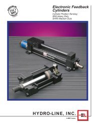
Cylinders - Lifco Hydraulics USA
Cylinders - Lifco Hydraulics USA
Cylinders - Lifco Hydraulics USA

You also want an ePaper? Increase the reach of your titles
YUMPU automatically turns print PDFs into web optimized ePapers that Google loves.
Hydro-Line Technical Data<br />
Rod Size and Stop Tube Selection<br />
S<br />
S<br />
T<br />
T<br />
S<br />
S<br />
T<br />
T<br />
S<br />
S<br />
S S<br />
S<br />
T<br />
T<br />
T T<br />
T<br />
S<br />
S<br />
S<br />
S<br />
T<br />
T<br />
T<br />
T<br />
D = 4S<br />
UNSUPPORTED ROD END<br />
D = S<br />
SUPPORTED ROD END<br />
D = 1/2S<br />
FIRMLY GUIDED ROD END<br />
D = 4S<br />
UNSUPPORTED ROD END<br />
T<br />
T<br />
T T<br />
T<br />
S<br />
S<br />
S S<br />
S<br />
D = S<br />
SUPPORTED ROD END<br />
D<br />
D<br />
D<br />
D<br />
D<br />
D<br />
D D<br />
D<br />
T<br />
T<br />
S<br />
S<br />
CAP CLEVIS<br />
OR TRUNNION<br />
INTERMEDIATE<br />
TRUNNION<br />
HEAD<br />
TRUNNION<br />
D = 1/2S<br />
FIRMLY GUIDED ROD END<br />
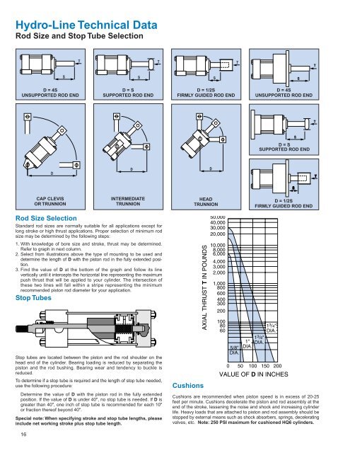
Rod Size Selection<br />
Standard rod sizes are normally suitable for all applications except for<br />
long stroke or high thrust applications. Proper selection of minimum rod<br />
size may be determined by the following steps:<br />
1. With knowledge of bore size and stroke, thrust may be determined.<br />
Refer to graph in next column.<br />
2. Select from illustrations above the type of mounting to be used and<br />
determine the length of D with the piston rod in the fully extended position.<br />
3. Find the value of D at the bottom of the graph and follow its line<br />
vertically until it intercepts the horizontal line representing the maximum<br />
push thrust that will be applied to your cylinder. The intersection of<br />
these two lines will fall within a stripe representing the minimum<br />
recommended piston rod diameter for your application.<br />
Stop Tubes<br />
Stop tubes are located between the piston and the rod shoulder on the<br />
head end of the cylinder. Bearing loading is reduced by separating the<br />
piston and the rod bushing. Bearing wear and tendency to buckle is<br />
reduced.<br />
To determine if a stop tube is required and the length of stop tube needed,<br />
use the following procedure:<br />
Determine the value of D with the piston rod in the fully extended<br />
position. If the value of D is under 40", no stop tube is needed. If D is<br />
greater than 40", one inch of stop tube is recommended for each 10"<br />
or fraction thereof beyond 40".<br />
Special note: When specifying stroke and stop tube lengths, please<br />
include net working stroke plus stop tube length.<br />
Cushions<br />
Cushions are recommended when piston speed is in excess of 20-25<br />
feet per minute. Cushions decelerate the piston and rod assembly at the<br />
end of the stroke, lessening the noise and shock and increasing cylinder<br />
life. Heavy loads that are attached to piston and rod assembly should be<br />
stopped by external means such as shock absorbers, springs, decelerating<br />
valves, etc. Note: 250 PSI maximum for cushioned HQ6 cylinders.<br />
16