Cylinders - Lifco Hydraulics USA
Cylinders - Lifco Hydraulics USA
Cylinders - Lifco Hydraulics USA

Create successful ePaper yourself
Turn your PDF publications into a flip-book with our unique Google optimized e-Paper software.
Table Of Contents<br />
Q6 Design Features...........................................................page 2<br />
Q6 Options........................................................................ page 3<br />
Port and Cushion Adjustment Locations............................page 3<br />
Port Sizes ..........................................................................page 3<br />
How to Order a Q6 Cylinder ..............................................page 4<br />
Hydro-Line <strong>Cylinders</strong> Application Data Sheet....................page 5<br />
Q6 Mounting Dimension Drawings .................................page 6-8<br />
Q6 3/4˝ and 1-1/8˝ Mounting Dimension Drawings ......page 9-10<br />
Q6T Series Air/Oil Tanks ..................................................page 11<br />
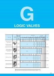
Q6 Options<br />
• Cushions<br />
• Oversized rod<br />
• Oversized NPTF and<br />
SAE ports<br />
• Stainless steel rod<br />
• Stop tube<br />
• Rod scraper<br />
• Fiberglass Tube<br />
• High temperature seals<br />
• Air/oil piston<br />
Q6 Special Modifications<br />
• Special Seals<br />
• Nonstd. mount<br />
• Oversize ports<br />
• Bronze bushings<br />
• Stainless steel rod<br />
• Stop tube<br />
• Nonrotating rod<br />
• Rod boots<br />
• Indicator switches<br />
• Double rod end<br />
• Rod boots<br />
• Nonrotating rod<br />
• Electroless nickel plated<br />
• Spring extend/return<br />
• Piston with magnetic ring<br />
• Rod end couplers<br />
• Studded rod ends<br />
• Hardened rods<br />
• Adjustable Stroke<br />
• Studded rod<br />
• Port or cushion modifications<br />
• Double-end rod with different<br />
rod ends<br />
• Special paint/plating<br />
• Linear displacement transducer<br />
• Adjustable stroke<br />
• Spring extend/return<br />
• Hardened rod<br />
Cylinder Mounting Accessories ..................................page 12-14<br />
Accessories for 3/4˝ and 1-1/8˝ Bore <strong>Cylinders</strong> ...............page 15<br />
Technical Data .................................................................page 16<br />
Low Profile Reed and Hall Effect Switches.................page 17-18<br />
Switch Specifications .......................................................page 19<br />
Rod End Styles ................................................................page 20<br />
Oversized Rod Information ..............................................page 21<br />
3/4˝ and 1-1/8˝ Bore Cylinder Dimensions.......................page 21<br />
Cylinder Dimensions...................................................page 22-23<br />
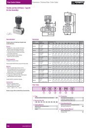
Port and Cushion Adjustment Locations<br />
Standard port locations are at No. 1,<br />
with optional locations at No. 2, 3 or 4.<br />
Standard cushion adjustment location is<br />
in location No. 2 (code C), with optional<br />
locations at C1, C3 or C4.<br />
Port Sizes<br />
Bore Undersize Standard SAE<br />
1 1 ⁄2, 2, 2 1 ⁄2<br />
1<br />
⁄4 NPTF 3<br />
⁄8 NPTF #6<br />
3 1 ⁄4, 4, 5 3<br />
⁄8 NPTF 1<br />
⁄2 NPTF #10<br />
6, 7, 8 1<br />
⁄2 NPTF 3<br />
⁄4 NPTF #12<br />
EXCEPTIONS:<br />
• Ports at No. 3 not available on E mount cap on 1 1 ⁄2" through<br />
3 1 ⁄4" bores.<br />
• Ports at No. 3 on B mount head and cap not available on 1 1 ⁄2"<br />
and 2" bores.<br />
• Standard NPTF and SAE ports at No. 3 on B mount head and<br />
cap not available on 3 1 ⁄4" bores.<br />
• Head cushion not available on 1 1 ⁄2" bore with 1" diameter rod.<br />
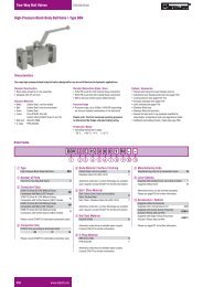
Specifications<br />
Bore sizes: w˝ through 8˝<br />
Pressure rating: 250 PSI air, 400 PSI hydraulic<br />
Temperature: -20°F to 400°F optional<br />
NFPA interchangeable mountings<br />
Q6: Pneumatic cylinders incorporate internally lubricated<br />
nitrile lip type piston and rod seals, which are permanently<br />
lubricated at assembly by filling the “v” groove with<br />
molybdenum disulfide grease.<br />
O-Ring Tube End Seals<br />
O-ring tube end seals in nitrile material are<br />
pressure compensating and reusable.<br />
Cushion Seals<br />
INTO CUSHION<br />
OUT OF CUSHION<br />
As the cylinder enters cushion, the new<br />
floating elastomeric cushion seal aligns itself<br />
on the cushion spear or collar. Sealing takes<br />
place on the spear or collar diameter and the<br />
back of the cushion seal pocket. Air trapped<br />
between the cushion and piston seal is<br />
metered out past the cushion adjustment<br />
needle to create the desired cushioning<br />
effect, dependent upon cylinder speed and<br />
load. As the cylinder comes out of cushion the<br />
cushion seal is unseated from the back of the<br />
pocket. Molded feet on the front face of the<br />
seal do not allow it to seal on the front of the<br />
pocket. Depressions molded into the outer<br />
diameter allow air to escape around the seal<br />
and work on the entire piston face for a quick<br />
break-away and stroke reversal. Due to this<br />
“self-checking” design, there is no need for<br />
ball checks.<br />
3