Cylinders - Lifco Hydraulics USA
Cylinders - Lifco Hydraulics USA
Cylinders - Lifco Hydraulics USA

Create successful ePaper yourself
Turn your PDF publications into a flip-book with our unique Google optimized e-Paper software.
4<br />
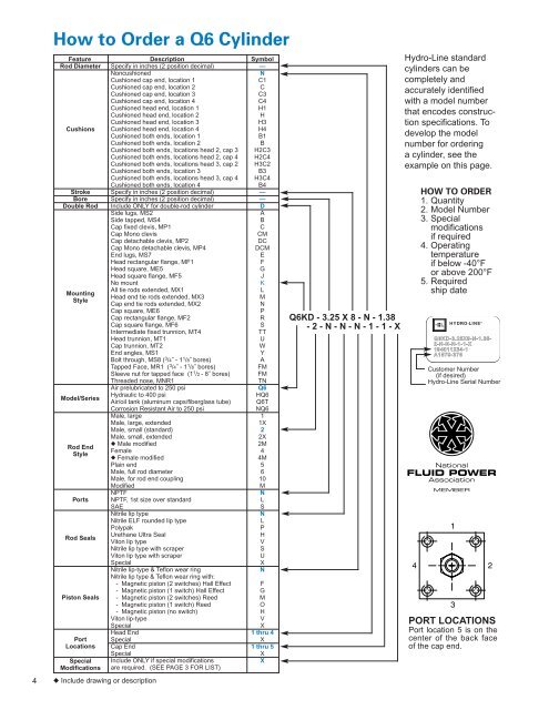
How to Order a Q6 Cylinder<br />
Feature Description Symbol<br />
Rod Diameter Specify in inches (2 position decimal) —<br />
Noncushioned<br />
N<br />
Cushioned cap end, location 1<br />
C1<br />
Cushioned cap end, location 2<br />
C<br />
Cushioned cap end, location 3<br />
C3<br />
Cushioned cap end, location 4<br />
C4<br />
Cushioned head end, location 1<br />
H1<br />
Cushioned head end, location 2<br />
H<br />
Cushioned head end, location 3<br />
H3<br />
Cushions Cushioned head end, location 4<br />
H4<br />
Cushioned both ends, location 1<br />
B1<br />
Cushioned both ends, location 2<br />
B<br />
Cushioned both ends, locations head 2, cap 3 H2C3<br />
Cushioned both ends, locations head 2, cap 4 H2C4<br />
Cushioned both ends, locations head 3, cap 2 H3C2<br />
Cushioned both ends, location 3<br />
B3<br />
Cushioned both ends, locations head 3, cap 4 H3C4<br />
Cushioned both ends, location 4<br />
B4<br />
Stroke Specify in inches (2 position decimal) —<br />
Bore Specify in inches (2 position decimal) —<br />
Double Rod Include ONLY for double-rod cylinder D<br />
Side lugs, MS2<br />
A<br />
Side tapped, MS4<br />
B<br />
Cap fixed clevis, MP1<br />
C<br />
Cap Mono clevis<br />
CM<br />
Cap detachable clevis, MP2<br />
DC<br />
Cap Mono detachable clevis, MP4<br />
DCM<br />
End lugs, MS7<br />
E<br />
Head rectangular flange, MF1<br />
F<br />
Head square, ME5<br />
G<br />
Head square flange, MF5<br />
J<br />
No mount<br />
K<br />
All tie rods extended, MX1<br />
L<br />
Mounting<br />
Head end tie rods extended, MX3<br />
M<br />
Style<br />
Cap end tie rods extended, MX2<br />
N<br />
Cap square, ME6<br />
P<br />
Cap rectangular flange, MF2<br />
R<br />
Cap square flange, MF6<br />
S<br />
Intermediate fixed trunnion, MT4<br />
TT<br />
Head trunnion, MT1<br />
U<br />
Cap trunnion, MT2<br />
W<br />
End angles, MS1<br />
Y<br />
Bolt through, MS8 ( 3 /4˝ - 1 1 /8˝ bores)<br />
A<br />
Tapped Face, MR1 ( 3 /4˝ - 1 1 /8˝ bores)<br />
FM<br />
Sleeve nut for tapped face (1 1 /2 - 8˝ bores) FM<br />
Threaded nose, MNR1<br />
TN<br />
Air prelubricated to 250 psi<br />
Q6<br />
Model/Series<br />
Hydraulic to 400 psi<br />
HQ6<br />
Air/oil tank (aluminum caps/fiberglass tube) Q6T<br />
Corrosion Resistant Air to 250 psi<br />
NQ6<br />
Male, large 1<br />
Male, large, extended<br />
1X<br />
Male, small (standard) 2<br />
Male, small, extended<br />
2X<br />
◆ Male modified<br />
2M<br />
Rod End<br />
Female 4<br />
Style<br />
◆ Female modified<br />
4M<br />
Plain end 5<br />
Male, full rod diameter 6<br />
Male, for rod end coupling 10<br />
Modified<br />
M<br />
NPTF<br />
N<br />
Ports NPTF, 1st size over standard<br />
L<br />
SAE<br />
S<br />
Nitrile lip type<br />
N<br />
Nitrile ELF rounded lip type<br />
L<br />
Polypak<br />
P<br />
Rod Seals<br />
Urethane Ultra Seal<br />
H<br />
Viton lip type<br />
V<br />
Nitrile lip type with scraper<br />
S<br />
Viton lip type with scraper<br />
U<br />
Special<br />
X<br />
Nitrile lip-type & Teflon wear ring<br />
N<br />
Nitrile lip type & Teflon wear ring with:<br />
- Magnetic piston (2 switches) Hall Effect F<br />
- Magnetic piston (1 switch) Hall Effect G<br />
Piston Seals - Magnetic piston (2 switches) Reed M<br />
- Magnetic piston (1 switch) Reed O<br />
- Magnetic piston (no switch) H<br />
Viton lip-type<br />
V<br />
Special<br />
X<br />
Head End 1 thru 4<br />
Port Special<br />
X<br />
Locations Cap End 1 thru 5<br />
Special<br />
X<br />
Special Include ONLY if special modifications<br />
X<br />
Modifications are required. (SEE PAGE 3 FOR LIST)<br />
◆ Include drawing or description<br />
Q6KD - 3.25 X 8 - N - 1.38<br />
- 2 - N - N - N - 1 - 1 - X<br />
Hydro-Line standard<br />
cylinders can be<br />
completely and<br />
accurately identified<br />
with a model number<br />
that encodes construction<br />
specifications. To<br />
develop the model<br />
number for ordering<br />
a cylinder, see the<br />
example on this page.<br />
HOW TO ORDER<br />
1. Quantity<br />
2. Model Number<br />
3. Special<br />
modifications<br />
if required<br />
4. Operating<br />
temperature<br />
if below -40°F<br />
or above 200°F<br />
5. Required<br />
ship date<br />
HYDRO-LINE ®<br />
Q6KD-3.25X8-N-1.38-<br />
2-N-N-N-1-1-X<br />
194011234-1<br />
A1579-375<br />
Customer Number<br />
(if desired)<br />
Hydro-Line Serial Number<br />
PORT LOCATIONS<br />
Port location 5 is on the<br />
center of the back face<br />
of the cap end.