Very High Speed Counter Module - Esco Drives & Automation
Very High Speed Counter Module - Esco Drives & Automation
Very High Speed Counter Module - Esco Drives & Automation
You also want an ePaper? Increase the reach of your titles
YUMPU automatically turns print PDFs into web optimized ePapers that Google loves.
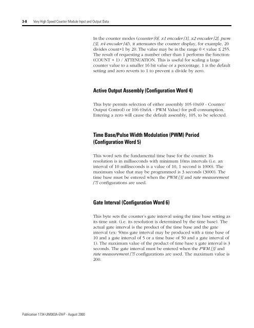
3-8 <strong>Very</strong> <strong>High</strong> <strong>Speed</strong> <strong>Counter</strong> <strong>Module</strong> Input and Output Data<br />
In the counter modes (counter [0], x1 encoder [1], x2 encoder [2], pwm<br />
[3], x4 encoder [4]), it attenuates the counter display, for example, 20<br />
divides count+1 by 20. The value may be in the range 0 < value ≤ 255.<br />
The result of requesting a number other than 1 performs the function:<br />
(COUNT + 1) / ATTENUATION. This is useful for scaling a large<br />
counter value to a smaller 16 bit value or a percentage. 1 is the default<br />
setting and zero reverts to 1 to prevent a divide by zero.<br />
Active Output Assembly (Configuration Word 4)<br />
This byte permits selection of either assembly 105 (0x69 - <strong>Counter</strong>/<br />
Output Control) or 106 (0x6A - PWM Value) for poll consumption.<br />
Entering a zero will cause the default assembly, 105, to be selected.<br />
Time Base/Pulse Width Modulation (PWM) Period<br />
(Configuration Word 5)<br />
This word sets the fundamental time base for the counter. Its<br />
resolution is in milliseconds with minimum 10ms intervals (i.e. an<br />
interval of 10 milliseconds is a value of 10, 1 second is 1000). The<br />
maximum value that may be programmed is 3 seconds (3000). The<br />
time base must be entered when the PWM [3] and rate measurement<br />
[7] configurations are used.<br />
Gate Interval (Configuration Word 6)<br />
This byte sets the counter’s gate interval using the time base setting as<br />
its time unit. (i.e. its resolution is determined by the time base). The<br />
actual gate interval is the product of the time base and the gate<br />
interval (ex: 50ms gate interval may be produced with a time base of<br />
10 and a gate interval of 5 or a time base of 50 and a gate interval of<br />
1). The maximum value of the product of time base x gate interval is 3<br />
seconds. The gate interval must be entered when the PWM [3] and<br />
rate measurement [7] configurations are used. The maximum value is<br />
200.<br />
Publication 1734-UM003A-EN-P - August 2000


