Very High Speed Counter Module - Esco Drives & Automation
Very High Speed Counter Module - Esco Drives & Automation
Very High Speed Counter Module - Esco Drives & Automation

You also want an ePaper? Increase the reach of your titles
YUMPU automatically turns print PDFs into web optimized ePapers that Google loves.
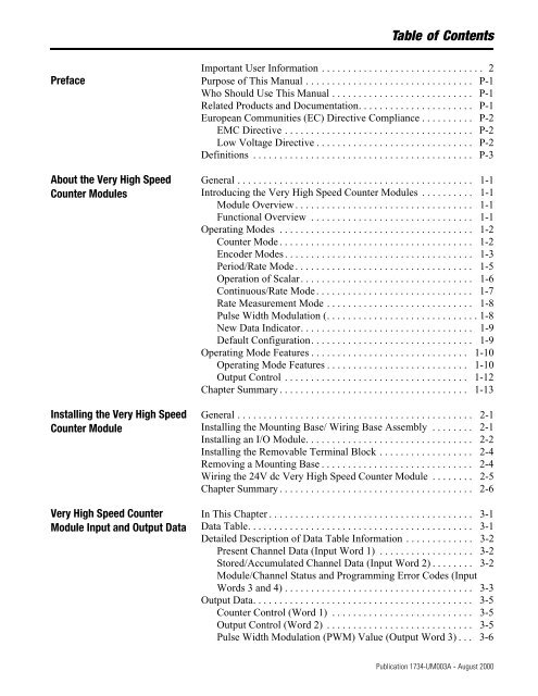
Table of Contents<br />
Important User Information . . . . . . . . . . . . . . . . . . . . . . . . . . . . . . . 2<br />
Preface Purpose of This Manual . . . . . . . . . . . . . . . . . . . . . . . . . . . . . . . . P-1<br />
Who Should Use This Manual . . . . . . . . . . . . . . . . . . . . . . . . . . . P-1<br />
Related Products and Documentation. . . . . . . . . . . . . . . . . . . . . . P-1<br />
European Communities (EC) Directive Compliance . . . . . . . . . . P-2<br />
EMC Directive . . . . . . . . . . . . . . . . . . . . . . . . . . . . . . . . . . . . P-2<br />
Low Voltage Directive . . . . . . . . . . . . . . . . . . . . . . . . . . . . . . P-2<br />
Definitions . . . . . . . . . . . . . . . . . . . . . . . . . . . . . . . . . . . . . . . . . . P-3<br />
About the <strong>Very</strong> <strong>High</strong> <strong>Speed</strong><br />
<strong>Counter</strong> <strong>Module</strong>s<br />
Installing the <strong>Very</strong> <strong>High</strong> <strong>Speed</strong><br />
<strong>Counter</strong> <strong>Module</strong><br />
<strong>Very</strong> <strong>High</strong> <strong>Speed</strong> <strong>Counter</strong><br />
<strong>Module</strong> Input and Output Data<br />
General . . . . . . . . . . . . . . . . . . . . . . . . . . . . . . . . . . . . . . . . . . . . . 1-1<br />
Introducing the <strong>Very</strong> <strong>High</strong> <strong>Speed</strong> <strong>Counter</strong> <strong>Module</strong>s . . . . . . . . . . 1-1<br />
<strong>Module</strong> Overview . . . . . . . . . . . . . . . . . . . . . . . . . . . . . . . . . . 1-1<br />
Functional Overview . . . . . . . . . . . . . . . . . . . . . . . . . . . . . . . 1-1<br />
Operating Modes . . . . . . . . . . . . . . . . . . . . . . . . . . . . . . . . . . . . . 1-2<br />
<strong>Counter</strong> Mode . . . . . . . . . . . . . . . . . . . . . . . . . . . . . . . . . . . . . 1-2<br />
Encoder Modes . . . . . . . . . . . . . . . . . . . . . . . . . . . . . . . . . . . . 1-3<br />
Period/Rate Mode . . . . . . . . . . . . . . . . . . . . . . . . . . . . . . . . . . 1-5<br />
Operation of Scalar. . . . . . . . . . . . . . . . . . . . . . . . . . . . . . . . . 1-6<br />
Continuous/Rate Mode . . . . . . . . . . . . . . . . . . . . . . . . . . . . . . 1-7<br />
Rate Measurement Mode . . . . . . . . . . . . . . . . . . . . . . . . . . . . 1-8<br />
Pulse Width Modulation (. . . . . . . . . . . . . . . . . . . . . . . . . . . . . 1-8<br />
New Data Indicator. . . . . . . . . . . . . . . . . . . . . . . . . . . . . . . . . 1-9<br />
Default Configuration. . . . . . . . . . . . . . . . . . . . . . . . . . . . . . . 1-9<br />
Operating Mode Features . . . . . . . . . . . . . . . . . . . . . . . . . . . . . . 1-10<br />
Operating Mode Features . . . . . . . . . . . . . . . . . . . . . . . . . . . 1-10<br />
Output Control . . . . . . . . . . . . . . . . . . . . . . . . . . . . . . . . . . . 1-12<br />
Chapter Summary . . . . . . . . . . . . . . . . . . . . . . . . . . . . . . . . . . . . 1-13<br />
General . . . . . . . . . . . . . . . . . . . . . . . . . . . . . . . . . . . . . . . . . . . . . 2-1<br />
Installing the Mounting Base/ Wiring Base Assembly . . . . . . . . 2-1<br />
Installing an I/O <strong>Module</strong>. . . . . . . . . . . . . . . . . . . . . . . . . . . . . . . . 2-2<br />
Installing the Removable Terminal Block . . . . . . . . . . . . . . . . . . 2-4<br />
Removing a Mounting Base . . . . . . . . . . . . . . . . . . . . . . . . . . . . . 2-4<br />
Wiring the 24V dc <strong>Very</strong> <strong>High</strong> <strong>Speed</strong> <strong>Counter</strong> <strong>Module</strong> . . . . . . . . 2-5<br />
Chapter Summary . . . . . . . . . . . . . . . . . . . . . . . . . . . . . . . . . . . . . 2-6<br />
In This Chapter . . . . . . . . . . . . . . . . . . . . . . . . . . . . . . . . . . . . . . . 3-1<br />
Data Table. . . . . . . . . . . . . . . . . . . . . . . . . . . . . . . . . . . . . . . . . . . 3-1<br />
Detailed Description of Data Table Information . . . . . . . . . . . . . 3-2<br />
Present Channel Data (Input Word 1) . . . . . . . . . . . . . . . . . . 3-2<br />
Stored/Accumulated Channel Data (Input Word 2) . . . . . . . . 3-2<br />
<strong>Module</strong>/Channel Status and Programming Error Codes (Input<br />
Words 3 and 4) . . . . . . . . . . . . . . . . . . . . . . . . . . . . . . . . . . . . 3-3<br />
Output Data. . . . . . . . . . . . . . . . . . . . . . . . . . . . . . . . . . . . . . . . . . 3-5<br />
<strong>Counter</strong> Control (Word 1) . . . . . . . . . . . . . . . . . . . . . . . . . . . 3-5<br />
Output Control (Word 2) . . . . . . . . . . . . . . . . . . . . . . . . . . . . 3-5<br />
Pulse Width Modulation (PWM) Value (Output Word 3) . . . 3-6<br />
Publication 1734-UM003A - August 2000