Very High Speed Counter Module - Esco Drives & Automation
Very High Speed Counter Module - Esco Drives & Automation
Very High Speed Counter Module - Esco Drives & Automation

Create successful ePaper yourself
Turn your PDF publications into a flip-book with our unique Google optimized e-Paper software.
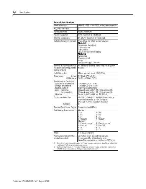
A-2 Specifications<br />
General Specifications<br />
<strong>Module</strong> Location<br />
1734-TB, -TBS, -TB3, -TB3S wiring base assembly<br />
Keyswitch Position 2<br />
Pointbus Current<br />
180mA maximum<br />
Power Dissipation<br />
1.9W maximum @ rated load<br />
Thermal Dissipation 6.5 BTU/hr maximum @ rated load<br />
Isolation Voltage (minimum) Prequalified for 1250V ac/rms between:<br />
<strong>Module</strong> 1<br />
System side (PointBus)<br />
Chassis ground<br />
A/B/Z inputs<br />
O0/O1 and user power supply<br />
<strong>Module</strong> 2<br />
System side<br />
Chassis ground<br />
Vaux +<br />
User power supply common<br />
External dc Power (does not<br />
represent power required to<br />
supply outputs)<br />
Field Power Bus<br />
Dimensions Inches<br />
(Millimeters)<br />
Environmental Conditions<br />
Operational Temperature<br />
Storage Temperature<br />
Relative Humidity<br />
Shock<br />
Operating<br />
Non-operating<br />
Vibration<br />
Conductors Wire Size<br />
Category<br />
Terminal Base Screw Torque<br />
No additional external power required to power<br />
module<br />
24V dc nominal; range 10-28.8V dc<br />
2.21H x 0.47W x 2.97L<br />
(56.0H x 12.0W x 75.5L)<br />
-20 to 55°C (-4 to 131°F)<br />
-40 to 85°C (-40 to 185°F)<br />
5 to 95% noncondensing<br />
30g peak acceleration, 11(±1)ms pulse width<br />
50g peak acceleration, 11(±1)ms pulse width<br />
Tested 5g @ 10-500Hz per IEC 68-2-6<br />
14 AWG (2.5mm 2 ) - 22 AWG (0.25mm 2 ) solid or<br />
stranded wire rated at 75°C or higher<br />
3/64 inch (1.2mm) insulation maximum<br />
2 2<br />
7 pound-inches (0.6Nm)<br />
Field Wiring Terminations <strong>Module</strong> 1<br />
0 - A 1 - Aret<br />
2 - B 3 - Bret<br />
4 - Z 5 - Zret<br />
6 - Output 0 7 - Output 1<br />
<strong>Module</strong> 2<br />
0 - Chassis ground 1 - Chassis ground<br />
2 - Return 0 3 - Return 1<br />
4 - -V 5 - -V<br />
6 - +V 7 - +V<br />
Mass<br />
1.15 oz/32.60 grams<br />
Agency Certification (when<br />
product is marked)<br />
CE marked for all applicable directives.<br />
C-Tick marked for all applicable acts.<br />
DeviceNet compatible as certified by ODVA, Inc.<br />
1 Off/on delay is time from a valid output “on” signal to output energization. On/off delay is time from<br />
a valid output “off” signal to output deenergization.<br />
2 Use this conductor category information for planning conductor routing as described in publication<br />
1770-4.1, “Industrial <strong>Automation</strong> Wiring and Grounding Guidelines.”.<br />
Publication 1734-UM003A-EN-P - August 2000