Lee's Gardens Redevelopment
Lee's Gardens Redevelopment
Lee's Gardens Redevelopment

You also want an ePaper? Increase the reach of your titles
YUMPU automatically turns print PDFs into web optimized ePapers that Google loves.
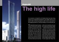
Construction of the Manulife Tower –<br />
<strong>Redevelopment</strong> of the previous<br />
Lee <strong>Gardens</strong> Hotel in Causeway Bay
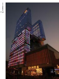
External view of Manulife Tower from various location
Block plan showing the building layout of the new Manulife Tower
Manulife Tower with a<br />
4-level retail podium
1/F and 3/F Layout Plan<br />
Circular-shaped atrium<br />
from 2 nd basement up to<br />
the podium on 5/F
Sky Garden<br />
aaa<br />
Entrance lobby<br />
with high<br />
headroom<br />
Typical floor plan and building section
Background Information about the <strong>Redevelopment</strong><br />
The project located in a 5,750 m2 site, which was abutted<br />
on 3 sides to small roads from 12 to 20m wide, and the<br />
remaining side adjoining a 17-storey residential building of<br />
28 years old. In addition to the congested environment,<br />
the project also required to demolish the 22-storey Lee<br />
Garden Hotel, with a 2-level basement structure in it.<br />
In the redevelopment, a new 50-storey office building, with<br />
total GFA of 83,860 m2, constructed in structural steel<br />
with a RC core, together with a 4-level basement, was to<br />
be built within a construction period of about 50 months,<br />
from demolition till final completion.
Contract arrangement<br />
The project was sub-divided into 3 parts:<br />
1. Demolition of the superstructure of the old Lee Garden<br />
Hotel<br />
2. Demolition of the old basement and the construction of<br />
the cut-off walling provision, foundation for the new<br />
building, and the core wall of the new building below<br />
ground level.<br />
3. Construction of the new building including the basement
Demolition of the old basement and Foundation<br />
Construction<br />
Though project of this kind is not exactly uncommon<br />
in Hong Kong, the following features, however, still<br />
make the redevelopment of the Lee Garden quite<br />
unique and thus imposed certain technical difficulties.<br />
1<br />
2<br />
A 2-level old basement structure covered the entire<br />
site area was to be demolished. Work was difficult for<br />
the old basement still took up the ground pressure.<br />
A 4-level basement of the same size was to be built to<br />
replace the old. Besides, a 5-level podium covering<br />
the entire site area was also built, that made the site<br />
extremely lack of working space during the<br />
construction.
3. Due to the old basement could not support those<br />
heavy plants which were required for the construction<br />
of the foundation using other mechanical means,<br />
hand-dug caissons were being used in this case.<br />
4. Temporary ground support and shoring were to be<br />
erected to take up the lateral pressure of soil while<br />
doing the demolition.<br />
5. Because of the inevitable sectioning and phasing<br />
arrangement involved in the demolition of the old<br />
basement, and, at the same time, to replace it with a<br />
new structure, complicated planning and construction<br />
jointing provisions were required.
6. While doing the major substructure and ground works,<br />
provisions to construct part of the future structure were<br />
carried out at the same time. These works include:<br />
- construction of the cut-off wall<br />
- foundation & cap for the core wall of the future<br />
tower,<br />
- erection of steel stanchions on top of the caisson<br />
as column support to facilitate the construction of<br />
the future basement using top-down method.<br />
7. The congested environment made storage and<br />
transportation arrangement within site very difficult. At a<br />
result of this, temporary loading platforms were provided<br />
at different locations to store the steel stanchions, to<br />
station mobile cranes or other excavating machines etc.
Works being done to facilitate the demolition of the<br />
old basement and the construction of substructure<br />
In order to have the old basement demolished and<br />
replaced by the construction of a new, as well as to<br />
make way and facilitate the construction of the new<br />
50-storey tower block, the following works were being<br />
carried out that comprised the whole contract.
1. Demolition support and ground stabilization<br />
• A series of temporary supporting system mainly in the<br />
form of steel shore and bracing were erected before<br />
various stages of basement demolition.<br />
• Form a grouted wall along the site perimeter down to<br />
3m below bedrock (average 25m deep) as a means of<br />
ground water control during excavation and construction<br />
of caissons.<br />
• Demolish part of the basement slab along the<br />
perimeter wall to give way for the construction of handdug<br />
caissons, which were used later as cut-off wall for<br />
the new basement structure. Totally 244 caissons of<br />
1.2m diameter were constructed for the purpose.
Early stages of basement<br />
demolition as seen in Early 1994
Later stages of basement demolition as seen in Early 1995
Erection of temporary shoring inside the<br />
basement at the same pace with demolition
Arrangement<br />
of temporary<br />
support<br />
during the<br />
basement<br />
demolition
Later stage of demolition at its peak
New steel columns for the new building<br />
was installed while the basement was<br />
under demolition at its later stage<br />
Demolition was carried out under very congested environment<br />
within the old basement with the temporary shore erected
Later stages of demolition<br />
Remaining portion of<br />
the old basement<br />
Portion where<br />
the ground<br />
floor slab for<br />
the new<br />
basement was<br />
under<br />
construction
2. Construction of new foundations<br />
•Excavate and construct the hand-dug caissons as<br />
foundation for the future building within the old<br />
basement. Totally 49 caissons with diameter<br />
ranging from 1.6m (for podium structure) to 5.0m<br />
(for main tower) were constructed.<br />
•Demolish the central part of the old basement to<br />
provide working space for the carrying out of the<br />
foundation and cap for the future building core.<br />
•Construct hand-dug caissons and the caisson cap<br />
that supported the central core of the new building.
• Excavation and construction of the 5m diameter<br />
caissons was done at the bottom of the pit that<br />
formed after the demolition of the centre part of the<br />
old basement.<br />
• After the completion of the caissons, another pit for<br />
the construction of the cap would start. The pit was<br />
supported by soldier piles and lagged with mild<br />
steel angles. The entire system was further strutted<br />
and braced by universal beam sections.<br />
• This cap sat on 7 caissons and was about 6m in<br />
depth. Due to the massive size and weight, it<br />
helped to hold down the entire basement from upheaving<br />
during demolition and excavation<br />
processes
Construction of caisson pile as<br />
cut-off and foundation to new building
Shoring and stud frame to<br />
stable the disrupted basement<br />
Sides of the old basement was<br />
disconnected to provide space for<br />
the working of the hand-dug caisson
Shoring support to stabilize<br />
the disturbed old basement<br />
Caisson as<br />
foundation for<br />
podium structure<br />
Caisson as<br />
cut-off provision<br />
Caissons that worked inside old basement
5m dia. Caisson worked inside<br />
the old basement as foundation<br />
for the Office Tower
Constructing the caisson foundation<br />
in the location of the future core wall
Forming the caisson cap for the<br />
support of the new tower core wall
3. Changing over and provisional works<br />
for the new building<br />
• Demolish the old basement structure along the<br />
perimeters and build the capping beam on top of the<br />
caisson wall.<br />
• Demolish part of the old basement structure for the<br />
erection of steel stanchions as column support to future<br />
building. These columns could enable the<br />
superstructure be constructed at the same time with the<br />
basement that was built using top-down method.<br />
• Rows of couplers were provided at basement floor<br />
levels to allow for necessary connection of the<br />
basement slab to the steel columns at a later stage.
• Construct the building core from the cap up to<br />
ground level. Since there was very limited working<br />
space within the central pit, traditional timber panel<br />
formwork was used in the construction of the core.<br />
• The core would act later as a lateral support for the<br />
ground floor slab which served also as a separating<br />
plate to facilitate the construction of the top-down<br />
basement.<br />
• At this moment, only half of the old basement was<br />
being demolished. The construction of the core was<br />
done in the central area with the remaining basement<br />
structure still under demolition at the same time. The<br />
problem of accessibility, clearing of debris formed by<br />
demolition and the assurance of safety etc. were the<br />
most headache part of the works at this stage.
• Demolish the remaining old basement, section by<br />
section, and covered the space immediately with the<br />
new ground floor slab. Phasing and junctioning<br />
arrangement was the most difficult part of work here.<br />
Finally the floor slab would infill the area between the<br />
central core and the capping beam.<br />
• Access provisions into the top-down basement and<br />
for removal of spoil were also provided on the ground<br />
slab. There were 3 of this access arrangement:<br />
- One was based on the permanent vehicular<br />
entrance,<br />
- the other one is a temporary opening formed on the<br />
Hysan Road side.<br />
- Using the atrium shaft as an access
Cut-off wall formed by secanttype<br />
hand-dug caisson<br />
Capping<br />
beam on top<br />
of the<br />
caisson cutoff<br />
Forming of the cut-off wall at the same time of<br />
demolition
Install steel columns<br />
into the partly<br />
demolished basement<br />
Crane<br />
supported on<br />
a temporary<br />
platform to<br />
assist in the<br />
placing of the<br />
steel columns
Column for<br />
office tower<br />
Close up detail of the<br />
steel columns inside the<br />
basement/caisson shaft<br />
Column for<br />
podium structure
Coupling arrangement to<br />
connect the steel column with<br />
the RC basement structure<br />
Bar coupler for<br />
connecting steel bar to<br />
floor beams or slab
Erection of floor formwork<br />
to construct the new<br />
ground floor slab<br />
Portion of old<br />
basement still<br />
under demolition<br />
Ground slab under<br />
construction<br />
Shifting over – majority of the old basement had been demolished,<br />
the vacated basement space was constructing the new ground<br />
floor slab as the first part of the top-down basement
Constructing the core wall at the later stage of<br />
demolition using manual timber form
Close up seeing the construction of the core wall<br />
inside the basement space
Gradual completion of the new ground slab<br />
and the replacement of the old basement
4. Works merging with the main contract<br />
• Erect the climb form system for the continual<br />
construction of the central core.<br />
• Construct the basement using top-down method.<br />
Excavation started from the ground downward until it<br />
reached a depth of 4 to 5 meter depending on the<br />
headroom of the basement, where it would be shored<br />
and strutted as an addition means of lateral support.<br />
• After that, basement slab would be constructed which<br />
was further connected to the central core, steel column<br />
and the caisson wall with couplers that were provided in<br />
advance.<br />
• The works repeated until it reached the bottom level<br />
of the basement where the caisson caps and other<br />
ground beams were then constructed.
Construction of the superstructure<br />
The podium<br />
The superstructure consists of a 5-level podium using<br />
for shopping/retail purpose and a 50-storey office tower.<br />
The podium was constructed in reinforced concrete with<br />
span max. up to 15m. There is an atrium space, circular<br />
in shape, than stretched from the 2 nd basement up to<br />
the 5 th Floor level. A 16m diameter skylight was erected<br />
on top of the atrium to provide natural lighting into the<br />
mall interior.<br />
The other side of the podium is the entrance lobby to<br />
the office tower. The headroom for this lobby is about<br />
18m and provided with a glazed skylight similar to the<br />
atrium area.
Construction of the superstructure<br />
The Office Tower<br />
The 50-storey office tower is a composite structure, that is,<br />
it is constructed with a RC core wall and the building frame<br />
embracing the core in structural steel.<br />
A climb-form using the VSL system was used to construct<br />
the core wall. The wall is trapezium-shaped with thickness<br />
ranging from 1.2m to 0.4m (thicker for lower floors).<br />
In order to make the core wall more rigid, projecting ribs<br />
were provided on the sides of the core. This made the<br />
forming of the core wall much difficult. The climb form thus<br />
had to erected with a lot of gantry type roller in order to<br />
make the formwork shutters more easy to open and close<br />
for steel fixing and other access purposes.
The steel frame was supported by steel columns starting<br />
from the 5m diameter caisson at the formation level of the<br />
basement.<br />
There were 15 steel columns of size 1.2m x 1.8m rising<br />
from the basement up to the 4/F where a transfer truss<br />
was located. From the transfer truss upward, the numbers<br />
of column increased due to the reduction of span in order<br />
to improve the structural efficacy.<br />
A second set of stiffening truss was located on 26/F. The<br />
purpose of this truss is to take up the loading imposed by<br />
the steel frame and transmit part of these loads onto the<br />
core wall. Instead of using a bracing-type outrigger, steel<br />
beams with larger section were used for the purpose.<br />
For the floor slab, typical composite slab with 150mm RC<br />
topping on steel floor beams were used.
Aa<br />
Construction of the<br />
structural steel frame
Structural steel frame before the erection of the transfer truss
Front elevation of the building seeing the re-aligning of the steel columns<br />
after the transfer truss on 4/F
Forming the transfer truss
Close-up view seeing the<br />
configuration of the<br />
stiffening truss on 26/F
Anchor frame embedded in core<br />
wall to allow welding connection<br />
for the steel floor beams
Connection of steel beams to the core wall
Temporary connecting<br />
clips to adjust alignment<br />
of members<br />
Join filled<br />
with weld<br />
Connection of steel columns
Connection of more<br />
complicated sections
Transformer for<br />
arc welding<br />
Cylinders for Oxyacetylene<br />
welding<br />
Equipment for welding
Replacing of welding wire<br />
into the auto feeding drum<br />
Semi-automatic welding using<br />
auto-feed welding wire and arc
Forming the composite floor slab<br />
Corrugated steel plank<br />
placed on top of the steel<br />
floor beams serving as a<br />
permanent formwork<br />
Welding of shear stud<br />
onto the steel beam<br />
stud
Placing concrete to form<br />
the composite floor slab
Construction of the core wall<br />
using the VSL Climb Form
Construction of the core wall started from<br />
the later stage of basement demolition.<br />
This part of the core wall was constructed<br />
using usual timber formwork
Erecting the Climb Form<br />
from the ground level<br />
Built-in anchor frame inside the<br />
core wall for connection of the<br />
steel beams to form the<br />
building frame at a later stage
Detail showing the gantry frame<br />
that support the climb form<br />
Hydraulic rod<br />
Work platform
Detail of hydraulic<br />
rod and support<br />
Guide rail<br />
Detail seeing the rails for<br />
the hanging of the panel<br />
shutters for the forming of<br />
the ribs on the core wall
Detail of the rail arrangement for<br />
the hanging of shutter panels
Stiffening<br />
ribs on sides<br />
of core wall<br />
Climb Form work to its typical cycle
Floor slab, internal<br />
walls and stairs etc.<br />
will be constructed<br />
later inside the interior<br />
space of the core wall
Construction of the<br />
Top-down Basement
Entrance to the basement<br />
making use of the<br />
permanent vehicular access<br />
Vehicular access to<br />
future basement carpark
Excavation inside<br />
the basement<br />
Floor slab completed<br />
in advance
Excavation inside the congested<br />
basement interior where the lateral<br />
support frame was still in place
Core wall<br />
Soldier pile wall for the cap was<br />
exposed (previously used for the<br />
excavation support for the cap)<br />
Excavation near the caisson<br />
cap for the core wall
Excavation down to the formation level<br />
where the caisson head was exposed
Forming the beam<br />
formwork using concrete<br />
block on blinded surface<br />
Trench formed by<br />
blockwork as<br />
beam formwork
Worker prepares for starter bar<br />
connection on the caisson cut-off<br />
to basement slab<br />
Secant caisson (cut-off)<br />
as the permanent<br />
basement wall<br />
Fixing of reinforcement<br />
for the ground beam at<br />
the formation level of<br />
the basement
A lifting crane was<br />
provided for the<br />
removal of spoil<br />
Temporary opening<br />
formed on basement<br />
floor for the operation<br />
of the grab
Opening making use of the atrium<br />
space on the retail podium for spoil<br />
removal purpose during the<br />
construction of the top-down basement
Bar coupler provided in<br />
the upper part of the<br />
encased column for<br />
onward bar connections<br />
Encasing the steel column<br />
with reinforced concrete
Erect formwork to the steel column before concreting
Placing of concrete in<br />
small quantity from<br />
the feeding hopper<br />
Gap later filled<br />
with cement grout<br />
Steel column finally encased and became a composite column
General construction difficulties encountered<br />
in this kind of projects<br />
Due to the complexity of the project, the followings are<br />
some of the difficulties that encountered during the<br />
construction processes.<br />
1. Works are sub-divided into a number of sections or<br />
phases (e.g. the demolition and basement advanced<br />
works)<br />
2. Various construction works were done at the same time<br />
using in close vicinity (e.g. core wall and structural steel<br />
frame, main building and podium)<br />
3. Material handling at the peak period, provision of<br />
transportation arrangement (e.g. steel members,<br />
concrete, excavated soil, curtain wall units)
4. Very complicated building services installation is often<br />
required<br />
5. Building finishes and internal fitting is also time<br />
consuming and required effective coordination
Curtain wall as the external<br />
envelop of a building
Installing the curtain –<br />
some difficult locations
The circular atrium<br />
space and the skylight
The atrium<br />
after finished
Finishing the<br />
office interior
Installation of the false ceiling<br />
with complicated interfacing<br />
works with the building services
Finishing the entrance lobby<br />
with very high headroom
End of Presentation