Wärtsilä 32 Product Guide
Wärtsilä 32 Product Guide
Wärtsilä 32 Product Guide
You also want an ePaper? Increase the reach of your titles
YUMPU automatically turns print PDFs into web optimized ePapers that Google loves.
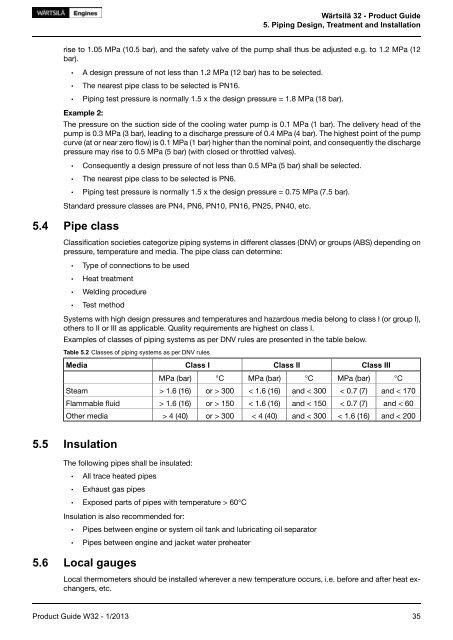
Wärtsilä <strong>32</strong> - <strong>Product</strong> <strong>Guide</strong><br />
5. Piping Design, Treatment and Installation<br />
rise to 1.05 MPa (10.5 bar), and the safety valve of the pump shall thus be adjusted e.g. to 1.2 MPa (12<br />
bar).<br />
• A design pressure of not less than 1.2 MPa (12 bar) has to be selected.<br />
• The nearest pipe class to be selected is PN16.<br />
• Piping test pressure is normally 1.5 x the design pressure = 1.8 MPa (18 bar).<br />
Example 2:<br />
The pressure on the suction side of the cooling water pump is 0.1 MPa (1 bar). The delivery head of the<br />
pump is 0.3 MPa (3 bar), leading to a discharge pressure of 0.4 MPa (4 bar). The highest point of the pump<br />
curve (at or near zero flow) is 0.1 MPa (1 bar) higher than the nominal point, and consequently the discharge<br />
pressure may rise to 0.5 MPa (5 bar) (with closed or throttled valves).<br />
• Consequently a design pressure of not less than 0.5 MPa (5 bar) shall be selected.<br />
• The nearest pipe class to be selected is PN6.<br />
• Piping test pressure is normally 1.5 x the design pressure = 0.75 MPa (7.5 bar).<br />
Standard pressure classes are PN4, PN6, PN10, PN16, PN25, PN40, etc.<br />
5.4 Pipe class<br />
Classification societies categorize piping systems in different classes (DNV) or groups (ABS) depending on<br />
pressure, temperature and media. The pipe class can determine:<br />
• Type of connections to be used<br />
• Heat treatment<br />
• Welding procedure<br />
• Test method<br />
Systems with high design pressures and temperatures and hazardous media belong to class I (or group I),<br />
others to II or III as applicable. Quality requirements are highest on class I.<br />
Examples of classes of piping systems as per DNV rules are presented in the table below.<br />
Table 5.2 Classes of piping systems as per DNV rules<br />
Media<br />
Class I<br />
Class II<br />
Class III<br />
MPa (bar)<br />
°C<br />
MPa (bar)<br />
°C<br />
MPa (bar)<br />
°C<br />
Steam<br />
> 1.6 (16)<br />
or > 300<br />
< 1.6 (16)<br />
and < 300<br />
< 0.7 (7)<br />
and < 170<br />
Flammable fluid<br />
> 1.6 (16)<br />
or > 150<br />
< 1.6 (16)<br />
and < 150<br />
< 0.7 (7)<br />
and < 60<br />
Other media<br />
> 4 (40)<br />
or > 300<br />
< 4 (40)<br />
and < 300<br />
< 1.6 (16)<br />
and < 200<br />
5.5 Insulation<br />
The following pipes shall be insulated:<br />
• All trace heated pipes<br />
• Exhaust gas pipes<br />
• Exposed parts of pipes with temperature > 60°C<br />
Insulation is also recommended for:<br />
• Pipes between engine or system oil tank and lubricating oil separator<br />
• Pipes between engine and jacket water preheater<br />
5.6 Local gauges<br />
Local thermometers should be installed wherever a new temperature occurs, i.e. before and after heat exchangers,<br />
etc.<br />
<strong>Product</strong> <strong>Guide</strong> W<strong>32</strong> - 1/2013 35


