
You also want an ePaper? Increase the reach of your titles
YUMPU automatically turns print PDFs into web optimized ePapers that Google loves.
<strong>VECTOR</strong> <strong>300</strong><br />
<strong>Service</strong> <strong>Manual</strong><br />
1
Contents<br />
1. INFORMATION<br />
1-1 Safety<br />
1-2 Notes<br />
1-3 Engine Specifications<br />
1-4 Serial Number<br />
1-5 Torque Values<br />
1-6 Special Tools<br />
2. MAINTENANCE<br />
2-1 Maintenance Data<br />
2-2 Maintenance Schedule<br />
2-3 Fuel Tube<br />
2-4 Throttle Operation<br />
2-5 Throttle Cable Adjustment<br />
2-6 Air Cleaner<br />
2-7 Spark Plug<br />
2-8 Idle Speed<br />
2-9 Drive Chain<br />
2-10 Brake System<br />
2-11 Wheels And Tires<br />
2-12 Steering Shaft Holder Bushing<br />
2-13 Toe-In<br />
3. ENGINE REMOVE AND INSTALLATION<br />
3-1 General Information<br />
3-2 Engine Removal<br />
3-3 Engine Installation<br />
4. LUBRICATION SYSTEM<br />
4-1 Mechanism Diagram<br />
4-2 Precautions In Operation<br />
4-3 Troubleshooting<br />
4-4 Engine Oil<br />
4-5 Engine Oil Strainer Clean<br />
4-6 Oil Pump<br />
4-7 Gear Oil<br />
5. FUEL SYSTEM<br />
5-1 Mechanism Diagram<br />
5-2 Precautions In Operation<br />
5-3 Trouble Diagnosis<br />
5-4 Carburetor Remove / Install<br />
5-5 Air Cut-Off Valve<br />
5-6 Throttle Valve<br />
5-7 Float Chamber<br />
5-8 Adjustment Of Idle Speed<br />
5-9 Fuel Tank<br />
5-10 Air Cleaner
6. CYLINDER HEAD/VALVE<br />
6-1 Mechanism Diagram<br />
6-2 Precautions In Operation<br />
6-3 Troubleshooting<br />
6-4 Cylinder Head Removal<br />
6-5 Cylinder Head Inspection<br />
6-6 Valve Stem Replacement<br />
6-7 Valve Seat Inspection And <strong>Service</strong><br />
6-8 Cylinder Head Reassembly<br />
6-9 Cylinder Head Installation<br />
6-10 Valve Clearance Adjustment<br />
7. CYLINDER/PISTON<br />
7-1 Mechanism Diagram<br />
7-2 Precautions In Operation<br />
7-3 Trouble Diagnosis<br />
7-4 Cylinder And Piston Removal<br />
7-5 Piston Ring Installation<br />
7-6 Piston Installation<br />
7-7 Cylinder Installation<br />
8. V-BELT DRIVING SYSTEM<br />
8-1 Mechanism Diagram<br />
8-2 Maintenance Description<br />
8-3 Trouble Diagnosis<br />
8-4 Left Crankcase Cover<br />
8-5 Drive Belt<br />
8-6 Drive Face<br />
8-7 Clutch Outer/Driven Pulley<br />
9. FINAL DRIVING MECHANISM<br />
9-1 Mechanism Diagram - Transmission Cover<br />
9-2 Precautions In Operation<br />
9-3 Trouble Diagnosis<br />
9-4 Disassembly Of Transmission<br />
9-5 Inspection Of Mission Mechanism<br />
9-6 Bearing Replacement<br />
9-7 Re-assembly Of Final Driving Mechanism<br />
10. ALTERNATOR/STARTING CLUTCH<br />
10-1 Mechanism Diagram<br />
10-2 Precautions In Operation<br />
10-3 Right Crankcase Cover Removal<br />
10-4 A.C.G. Set Removal<br />
10-5 Right Cover Bearing<br />
10-6 Flywheel Removal<br />
10-7 Starting Clutch<br />
10-8 Flywheel Installation<br />
10-9 A.C.G. Set Installation<br />
10-10 Right Crankcase Cover Installation
11. CRANKCASE / CRANK<br />
11-1 Mechanism Diagram<br />
11-2 General Information<br />
11-3 Trouble Diagnosis<br />
11-4 Disassembly Of Crankcase<br />
11-5 Crankshaft Inspection<br />
11-6 Assembly Of Crankcase<br />
12. COOLING SYSTEM<br />
12-1 Mechanism Diagram<br />
12-2 General Information<br />
12-3 Trouble Diagnosis<br />
12-4 Trouble Diagnosis For Cooling System<br />
12-5 System Test<br />
12-6 Radiator<br />
12-7 Water Pump<br />
12-8 Thermostat<br />
13. STEERING AND SUSPENSION<br />
13-1 Parts Drawing<br />
13-2 Troubleshooting<br />
13-3 Handlebar<br />
13-4 Throttle Housing<br />
13-5 Steering System<br />
14. FRONT WHEEL AND BRAKE SYSTEM<br />
14-1 Parts Drawing<br />
14-2 Troubleshooting<br />
14-3 Front Wheels<br />
14-4 Hydraulic Brake<br />
14-5 Suspension Adjustment<br />
15. REAR WHEEL AND BRAKE SYSTEM<br />
15-1 Parts Drawing<br />
15-2 Troubleshooting<br />
15-3 Remove Rear Wheel And Rear Brake<br />
15-4 Swingarm & Rear Axle Holder<br />
15-5 Suspension Adjustment<br />
16. FENDERS AND EXHAUST PIPE<br />
16-1 Fenders Drawing<br />
16-2 Rear Fenders Removal<br />
16-3 Front Fender Removal<br />
16-4 Exhaust Pipe Removal
17. ELECTRICAL SYSTEM<br />
17-1 Troubleshooting<br />
17-2 Ignition Coil<br />
17-3 Ignition Timing<br />
17-4 Battery Information<br />
17-5 Electric Starter<br />
17-6 Light Bulbs Replacement<br />
17-7 Instrument Pane<br />
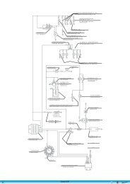
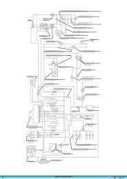
17-8 Wiring Diagram<br />
18.TROUBLESHOOTING<br />
18-1 Engine Can Not Work<br />
18-2 Poor Performance At Low And Idle Speeds<br />
18-3 Poor Performance At High Speed<br />
18-4 Loss Power<br />
18-5 Poor Handling
1. INFORMATION<br />
1-1 Safety<br />
1-2 Notes<br />
1-3 Engine Specifications<br />
1-4 Serial Number<br />
1-5 Torque Values<br />
1-6 Special Tools<br />
1-1 Safety<br />
GASOLINE<br />
Gasoline is extremely flammable and is explosive under certain condition.<br />
Do not smoke or allow sparks or flames in your work area.<br />
● CARBON MONOXIDE<br />
Never run the engine in a closed area. The exhaust contains poisonous carbon<br />
monoxide gas that may cause loss of consciousness and lead to death.<br />
● BATTERY ELECTROLYTE<br />
The battery electrolyte contains sulfuric acid. Protect your eyes, skin and<br />
clothing. If you contact it, flush thoroughly with water and call a doctor if electrolyte<br />
gets in your eyes.<br />
● HOT PARTS<br />
Engine and exhaust pipe become very hot and remain hot for one hour after the<br />
engine is run. Wear insulated gloves before handling these parts.<br />
● USED ENGINE/GEAR OIL<br />
Used engine oil and gear oil may cause skin disease if repeatedly contact with<br />
the skin for long periods.<br />
Keep out of reach of children.<br />
1-2 Notes<br />
All information, illustrations, directions and specifications included in this publication are base on the latest<br />
product information available at the time of approval for printing.<br />
JI-EE Dynamic Technology Industry Co., Ltd. reserves the right to make changes at any time without notice and<br />
without incurring any obligation whatever.<br />
No part of this publication may be reproduced without written permission.<br />
6
1-3 Engine Specifications<br />
Type<br />
4 Stroke,Single Cylinder, Water cooled<br />
Displacement<br />
287.2c.c.<br />
Bore and Stroke<br />
75 mm x 65 mm<br />
Compression 10.0:1<br />
Maximum Hp 20ps / 6500<br />
Maximum Torque (Nm/rpm) 24.6 Nm / 5000<br />
Carburetor<br />
Ignition<br />
DC-CDI<br />
Starting<br />
Electric<br />
Lubrication<br />
Auto oil injection<br />
Transmission<br />
Automatic (C.V.T. V-belt + Reverse)<br />
CHASSIS<br />
Overall Length<br />
Overall Width<br />
Overall Height<br />
Wheel base<br />
Ground Clearance<br />
Dry Weight<br />
Fuel Tank Capacity<br />
1815mm<br />
1062mm<br />
1130mm<br />
1193mm<br />
150mm<br />
225Kg<br />
12L<br />
SUSPENSION<br />
Front<br />
Double A-Arm & Adjustable<br />
Rear<br />
Swing Arm & Adjustable Shock<br />
BRAKES<br />
Front Front Hydraulic Disc*2<br />
Rear<br />
Rear Hydraulic Disc*1<br />
TIRES<br />
Front 21x7-10<br />
Rear 22x10-10<br />
PRESSURE【 psi ( kgf/cm2)】<br />
Front 12(0.8)<br />
Rear 12(0.8)<br />
COLORING<br />
Specifications subject to change without notice.<br />
7
1-4 Serial Number<br />
The frame serial number is stamped on the front of the frame.<br />
The engine serial number is stamped on the left side of the crankcase.<br />
Frame serial number<br />
8
1-5 Torque Values<br />
STANDARD<br />
● 5 mm bolt and nut<br />
● 6 mm bolt and nut<br />
● 8 mm bolt and nut<br />
●10 mm bolt and nut<br />
●12 mm bolt and nut<br />
ENGINE<br />
● Cylinder head nut<br />
● Spark plug<br />
● Cylinder head bolt<br />
● Alternator bolt<br />
5 N.m (3.5 lbf.ft)<br />
10 N.m (7.2 lbf.ft)<br />
22 N.m (16 lbf.ft)<br />
35 N.m (25 lbf.ft)<br />
55 N.m (40 lbf.ft)<br />
38 N.m (27.4 lbf.ft)<br />
12 N.m (8.9 lbf.ft)<br />
15 N.m (10.1 lbf.ft)<br />
8 N.m (5.9 lbf.ft)<br />
FRAME<br />
● Handlebar upper holder bolt<br />
● Throttle housing cover screw<br />
● Steering shaft nut<br />
● Steering shaft holder bolt<br />
● Wheel rim bolt<br />
● Tie rod lock nut<br />
● King pin nut<br />
● Handlebar lower holder nut<br />
● Front wheel bolt<br />
● Front axle castle nut<br />
● Front brake arm nut<br />
● Rear brake arm nut<br />
● Rear axle castle nut<br />
● Rear wheel bolt<br />
● Exhaust muffler mounting bolt<br />
● Engine hanger bolt<br />
● Rear axle holder bolt<br />
● Swing arm pivot nut<br />
● Rear shock absorber mounting nut<br />
24 N.m (17.7 lbf.ft)<br />
4 N.m (2.9 lbf.ft)<br />
50 N.m (36.9 lbf.ft)<br />
33 N.m (24 lbf.ft)<br />
18 N.m (13.3 lbf.ft)<br />
35 N.m (25.8 lbf.ft)<br />
40 N.m (29 lbf.ft)<br />
40 N.m (29.5 lbf.ft)<br />
24 N.m (17.7 lbf.ft)<br />
40-60 N.m (30-45 lbf.ft)<br />
4 N.m (3.0 lbf.ft)<br />
7 N.m (5.2 lbf.ft)<br />
40-60 N.m (30-45 lbf.ft)<br />
24 N.m (17.7 lbf.ft)<br />
30 N.m (22.1 lbf.ft)<br />
30 N.m ( 22 lbf.ft)<br />
90 N.m (65 lbf.ft)<br />
90 N.m (65 lbf.ft)<br />
45 N.m (33 lbf.ft)<br />
Nuts, Bolts Tightness<br />
Perform periodical maintenance in accord with the Periodical Maintenance Schedule Check if all<br />
bolts and nuts on the frame are tightened securely.<br />
Check all fixing pins, snap rings, hose clamp, and wire holders for security.
1-6 Special Tools<br />
For Frame<br />
1. Adjustable Hook Spencer<br />
(E1105-LRA0-FT1)<br />
Purpose: Adjusting of suspension<br />
2. Ball Joint Puller(E0205-LRA0-FT1)<br />
Purpose: Taking out the ball joint from front knuckle as repairing.<br />
10
For Engine<br />
1.TACKING ACG FLY WHEEL TOOL<br />
(C1110-RB1-FT1)<br />
2. COUNTER SHIFT IMPLEMENT (I1003-RB1-FT1)<br />
3. ADJUST TAPPET IMPLEMENT<br />
(A4721-HMA-FT1)<br />
4. SLEEVE OF FABRICATING TRANSMISSION<br />
SHAFT & OIL SEAL (I1202-RB1-FT1)<br />
11
5. SLEEVE OF FABRICATING L CRANK & OIL<br />
SEAL (I1201-HMA-FT1)<br />
6. TAKING 6205 BRG. TOOL (I6150-6205-FT1)<br />
7.6205 BRG. KNOCK TOOL (I6150-6205-FT2)<br />
8. L CRANK CASE COVER 6006 BRG. FABRICATING TOOL<br />
(I6150-6006-FT1)<br />
12
9. FABRICATING R CRANK CASE COVER 6201<br />
BRG. TOOL (I6140-6201-FT1)<br />
10. TAKING BRG. RB1 TOOL (I6150-RB1-FT1)<br />
11. PNEUMATIC TAKING BRG. 6205 TOOL (I6150-6205-FT3)<br />
12. TAKING TAPPET PIN TOOL (A4451-HMA-FT1)<br />
13
13. <br />
<br />
B3411-RB1-FT1<br />
<br />
<br />
<br />
<br />
<br />
<br />
<br />
<br />
<br />
<br />
<br />
<br />
<br />
<br />
<br />
<br />
<br />
<br />
<br />
14. <br />
<br />
I6100-6305-FT1<br />
<br />
<br />
<br />
<br />
<br />
<br />
<br />
<br />
<br />
<br />
<br />
<br />
<br />
15. KNOCKING BRG.(6901) WATER PUMP IMPLEMENT<br />
(I1001-KJ9-FT1)<br />
14
16. KNOCKING WATER PUMP OIL SEAL IMPLEMENT (INSIDE)<br />
(I1205-KF0-FT1 )<br />
17. KNOCKING WATER PUMP OIL SEAL(IRON) IMPLEMENT<br />
(A9217-H9A-FT1)<br />
18. TAKING & LOCKING SPECIAL NUT 36MM SLEEVE<br />
(I0202-HMA-FT1)<br />
19. TAKING & FABRICATING IN. VALVE TOOL<br />
(A4711-HMA-FT1)<br />
15
20. TAKING BRG. 62040 LARGE-SIZE TOOL<br />
(I6100-6204-FT3 )<br />
21. ALL-PURPOSE FIXER (B2101-HMA-FT1)<br />
22. KNOCKING BRG.(6204) IMPLEMENT<br />
(I6100-6204-FT2)<br />
16
2. MAINTENANCE<br />
2-1 Maintenance Data 2-8 Idle Speed<br />
2-2 Maintenance Schedule 2-9 Drive Chain<br />
2-3 Fuel Tube 2-10 Brake System<br />
2-4 Throttle Operation 2-11 Wheels And Tires<br />
2-5 Throttle Cable Adjustment 2-12 Steering Shaft Holder Bushing<br />
2-6 Air Cleaner 2-13 Toe-In<br />
2-7 Spark Plug<br />
2-1 Maintenance Data<br />
SPECIFICATION<br />
SPARK PLUG<br />
SPARK PLUG GAP<br />
RECOMMENDED SPARK PLUGS<br />
THROTTLE LEVER FREE PLAY<br />
IDLE SPEED<br />
BRAKE LEVER FREE PLAY<br />
DRIVE CHAIN SLACK<br />
TOE-IN<br />
0.8 mm<br />
NGK CR8E<br />
5-10 mm<br />
1700±100 rpm<br />
15-25 mm<br />
10-25 mm<br />
5±10 mm<br />
TORQUE VALUES<br />
SPARK PLUG<br />
TIE-ROD LOCK NUT<br />
ENGINE OIL<br />
GEAR LUBRICATION OIL<br />
12-19 N.m<br />
35-43 N.m<br />
1.4 Liter (1.2Liter for change)<br />
750cc (650cc for change)<br />
17
2-2 Maintenance Schedule<br />
The internal maintenance in the following table is based on average riding, normal conditions.<br />
Riding in unusually dusty areas, require more frequent servicing.<br />
<strong>300</strong>KM Every Every Every Every Notes<br />
1 Month 3 Months 6 Months 1 Year 2 Years<br />
Fuel Lines I I R<br />
Throttle Operation I I<br />
Air Filter I C R<br />
Fuel Filter<br />
R<br />
Spark Plug I I R<br />
Drive Chain I, L Lubricate for every 1 month<br />
Brake Shoes<br />
I<br />
Brake System I I<br />
Brake Fluid I R<br />
Nuts, Bolts & Fasteners I<br />
WHEEL/TIRES I I<br />
Wheels I I<br />
Steering System I I<br />
Suspension System I I<br />
C.V.T Drive belt I R<br />
Transmission Oil R Replace for every 3,000km or 6 Months<br />
Engine Oil R Replace for every 3,000km or 6 Months<br />
Battery I I,C I,C<br />
Oil Filter (Screen) C C<br />
Valve Clearance I I<br />
Coolant I I R<br />
Cooling Fan I I<br />
Carburetor (Idle Speed) I I<br />
Choke<br />
I<br />
Note – I: Inspect and Clean, Adjust, Lubricate or Replace, if necessary<br />
C: Clean L: Lubricate R: Replace<br />
2-3 Fuel Tube<br />
Inspect the fuel lines for deterioration, damaging or<br />
leakage and replace if necessary.<br />
18
2-4 Throttle Operation<br />
Inspect for smooth throttle lever full opening and automatic<br />
full closing in all steering positions.<br />
Inspect if there is no deterioration, damage or kink in the<br />
throttle cable, replace it if necessary.<br />
Check the throttle lever, free play is 5-10 mm at the tip of the<br />
throttle lever.<br />
Disconnect the throttle cable at the upper end.<br />
Lubricate the cable with commercially lubricant to prevent<br />
premature wear.<br />
Throttle<br />
2-5 Throttle Cable Adjustment<br />
Slide the rubber cap of the adjuster off the throttle<br />
Housing, loosen the lock nut and adjust the free play<br />
of the throttle lever by turning the adjuster on the throttle housing.<br />
Inspect the free play of the throttle lever.<br />
2-6 Air Cleaner<br />
Please remove the four hooks, and then disassemble<br />
two screws inside the air cleaner case.<br />
Pull out the air filter element from the air cleaner case.<br />
Washing the element in non-flammable solvent, squeeze<br />
out the solvent thoroughly.<br />
Let it dry.<br />
Soak the filter element in gear oil and then squeeze<br />
out the excess oil.<br />
Install the every component into air cleaner in the reverse order of<br />
removal.<br />
Note: for more detail please check chapter 5-10<br />
2-7 Spark Plug<br />
This spark plug is located at the front of the engine.<br />
Disconnect the spark plug cap and unscrew the spark plug.<br />
Check the condition of spark plug electrodes wear.<br />
19
Change a new spark plug if the electrodes and insulator tip appear unusually fouled or burned.<br />
Discard the spark plug if there is apparent wear or if the insulator is cracked or chipped.<br />
The spark plug gap shall keep in 0.8mm<br />
With the sealing washer attached, thread the spark plug in by hand to prevent crosses threading.<br />
Tighten the spark plug with 1.0~1.2kgf-m<br />
2-8 Idle Speed<br />
Connect an engine speed meter.<br />
Warm up the engine, 10 minutes are enough.<br />
Turn the idle-speed adjust screw on the carburetor to obtain the idle speed. “Turn in” (clockwise) will<br />
get higher speed. “Turn out” (counter clockwise) will get lower speed.<br />
IDLE SPEED: 1700±100 rpm<br />
2-9 Drive Chain<br />
Stopping the ATV and shift the transmission into neutral(N) .<br />
Measure the drive chain slack midway between the<br />
sprockets.<br />
Chain slack =15~25mm (5/8~1 inch)<br />
Adjust the chain slack.<br />
Loosen the lock nuts and turn drive chain adjusting nuts<br />
until get the correct slack.<br />
Tighten the axle holder bolts.<br />
Torque = 90N.m (65 lbf.ft)<br />
When the drive chain becomes very dirty, it should be removed, cleaned and lubricated by specify lubricator.<br />
Please use special chain oil to lubricate the drive chain.<br />
Clean the drive chain with kerosene and wipe it dry.<br />
Inspect the drive chain for any possible wearing or damaging.<br />
Replace the chain, if it is worn excessively or damaged.<br />
Inspect the sprocket teeth, if it is excessive wearing or damaging,<br />
please replace it.<br />
20
2-10 Brake System<br />
Inspect the front brake lever and cable for excessive play or other<br />
damage.<br />
Replace or repair if necessary.<br />
Measure the brake lever free play at the end of the brake lever trip.<br />
Front Brake lever free play is 15-25 mm.<br />
Adjustable nut<br />
Brake lever<br />
Parking Brake<br />
Turn the parking brake to the left side is “parking off”, while<br />
turn to right side is “parking on”. As you found out the<br />
parking brake which has been decreased its brake ability, you<br />
might screw the adjustable nut to modify the clearance of<br />
brake shoe to the correct position. Also, another method of<br />
adjustment of parking brake, please refer to next page.<br />
Parking Off<br />
Inspect the rear brake lever and cable for excessive<br />
play or other damage.<br />
Replace or repair if necessary.<br />
Measure the rear brake lever free play at the<br />
end of the lever trip.<br />
Adjustable nut<br />
Parking On<br />
Rear Brake lever free play is 15-25 mm.<br />
21<br />
Brake level<br />
Adjustment
NOTE:<br />
• The second method to adjust brake level is under the driver<br />
seat and rear brake component.<br />
• In order to avoid a pre-load occurred between brake disk and<br />
lining. After all adjusting of brake system are completed,<br />
please check the small clearance between brake disk and<br />
lining.<br />
Rear Brake<br />
Front Brake<br />
Adjustable nut<br />
Loosen the adjustable nut near the rear brake caliper. Screw the<br />
adjustable bolt by hand with C.W. turn to the end, then back to a<br />
quarter turn. Tighten the nut to complete the parking brake<br />
adjustment.<br />
Also, as you fount out the brake ability which is a bit insufficient,<br />
you can screw the adjustable nut of parking Brake.<br />
Parking Brake Adjustable nut<br />
22
2-11 Wheels And Tires<br />
Inspect the tire surfaces for cuts, nails or other sharp objects.<br />
Check the each tire surface at cold tire condition.<br />
*The standard of tire pressure is 12(0.8) psi ( kgf/cm2)<br />
2-12 Steering Shaft Holder Bushing<br />
Remove the front fender first.<br />
Remove the steering shaft holder and check the steering shaft bushing<br />
for wears or damage.<br />
If the bushing is worn or damaged, please change a new one.<br />
Grease the steering shaft bushing and install the parts<br />
in the reverse order of removal.<br />
Torque: steering shaft holder bolt: 33 N.m (24 lbf.ft)<br />
2-13 Toe-In<br />
Keep the vehicle on level ground and the front wheels facing straight<br />
ahead.<br />
Mark the centers of the tires to indicate the axle center height.<br />
Measure the distance between the marks.<br />
Carefully to move the vehicle back, let the wheels turn 180 degree,<br />
so the marks on the tires are aligned with the axle center height.<br />
Measure the distance between the marks.<br />
Calculate the difference in the front and rear measurements.<br />
Toe-in: 5±10mm<br />
23
If the toe-in is out of standard, adjust it by changing<br />
the length of the tie-rods equally by turning the tie-rod<br />
while holding the ball joint.<br />
Tighten the lock nuts.<br />
Torque: 35-43 N.m<br />
Lock Nuts<br />
24
3. ENGINE REMOVE AND INSTALLATION<br />
3-1 General Information 3-3 Engine Installation<br />
3-2 Engine Removal<br />
3.1 General Information<br />
ENGINE SHALL BE REMOVED IN THE CONDITIONS OF NECESSARY REPAIRMENT OR<br />
ADJUSTMENT TO THE TRANSMISSION AND COMBUSTION SYSTEM ONLY<br />
3-2 Engine Removal<br />
Before removing engine, you need to remove all of components such as seat, front and back fender,<br />
fuel tube, exhaust pipe, carburetor cable and drive chain…etc. You can then see three hanger bolts which have<br />
screwed on engine.<br />
Loosen these three hanger bolts. You have succeeded to remove this engine.<br />
There are some pictures to describe main step of removing engine.<br />
Disconnect the wire connectors. There are three connectors for<br />
carburetor auto-choke, starter motor and generator respectively.<br />
Remove the drive chain cover.<br />
Remove the drive chain retaining clip and master link,<br />
and remove the drive chain.<br />
Hanger bolt<br />
25
3-3 Engine Installation<br />
The Engine installation is essentially in the reverse order of removal.<br />
The torque of engine hanger bolt is 30 N.m<br />
Route the wires and cable in reverse order properly.<br />
26
4. LUBRICATION SYSTEM<br />
4-1 Mechanism Diagram<br />
4-2 Precautions In Operation<br />
4-3 Troubleshooting<br />
4-4 Engine Oil<br />
4-1 Mechanism Diagram<br />
4-5 Engine Oil Strainer Clean<br />
4-6 Oil Pump<br />
4-7 Gear Oil<br />
Valve Rocker Arm<br />
Press-In Lubrication<br />
Oil Route<br />
Cam Shaft<br />
Spray Lubrication<br />
Con-Rod<br />
Oil Route<br />
Spray Lubrication<br />
Press-In Lubrication<br />
Rotate Direction<br />
Oil Pump<br />
Oil Strainer<br />
27
4-2 Precautions In Operation<br />
General Information:<br />
• This chapter contains maintenance operation<br />
for the engine oil pump and gear oil<br />
replacement.<br />
Specifications<br />
Engine oil quantity Disassembly: 1400 c.c.<br />
Change: 1200c.c.<br />
Oil viscosity SAE 10W-30 (Recommended<br />
King serial oils)<br />
Gear oil Disassembly: 750c.c.<br />
Change: 650c.c.<br />
Gear oil viscosity SAE 140<br />
(Recommended SYM Hypoid gear oils)<br />
單 位 :mm<br />
Items Standard (mm) Limit (mm)<br />
Inner rotor clearance 0.15 0.20<br />
Oil pump<br />
Clearance between outer rotor and body 0.15~0.20 0.25<br />
Clearance between rotor side and body 0.04~0.09 0.12<br />
Torque value<br />
Torque value oil strainer cap<br />
Engine oil drain bolt<br />
Gear oil drain bolt<br />
Gear oil join bolt<br />
Oil pump connection bolt<br />
1.5~3.0kgf-m<br />
1.9~2.5kgf-m<br />
1.0~1.5kgf-m<br />
1.0~1.5kgf-m<br />
0.8~1.2kgf-m<br />
4-3 Troubleshooting<br />
Low engine oil level<br />
• Oil leaking<br />
• Valve guide or seat worn out<br />
• Piston ring worn out<br />
Dirty oil<br />
• No oil change in periodical<br />
• Cylinder head gasket damage<br />
• Piston ring worn out<br />
Low oil pressure<br />
• Low engine oil level<br />
• Clogged in oil strainer, circuits or pipes<br />
• Oil pump damage<br />
28
4-4 Engine Oil<br />
Turn off engine, and park the ATV in flat surface<br />
with main stand.<br />
Check oil level with oil dipstick.<br />
So not screw the dipstick into engine as checking.<br />
If oil level is nearly low level, fill out<br />
recommended oil to upper level.<br />
Oil Change<br />
Caution<br />
Drain bolt<br />
Drain oil as engine warmed up so that makes sure<br />
oil can be drained smoothly and completely.<br />
Place an oil pan under the ATV, and remove oil<br />
drain bolt.<br />
After drained, make sure washer can be re-used.<br />
Install oil drain bolt.<br />
Torque value:1.9~2.5kgf-m<br />
4-5 Engine Oil Strainer Clean<br />
Drain engine oil out.<br />
Remove oil strainer and spring.<br />
Clean oil strainer.<br />
Check if O-ring can be re-used.<br />
Install oil strainer and spring.<br />
Install oil strainer cap.<br />
Torque value:1.5~3.0kgf-m<br />
Add oil to crankcase (oil viscosity SAE 10W-30)<br />
Recommended using King serial oil.<br />
Engine oil capacity: 1200c.c. when replacing<br />
Install dipstick, start the engine for running<br />
several minutes.<br />
Turn off engine, and check oil level again.<br />
Check if engine oil leaks.<br />
Oil strainer cap<br />
O-ring<br />
Oil strainer<br />
29
4-6 Oil Pump<br />
Oil Pump Removal<br />
Remove generator and starting gear. (Refer to<br />
chapter 10) 。<br />
Remove cir clip and take out oil pump driving<br />
chain and sprocket.<br />
Clip<br />
Make sure that pump shaft can be rotated freely.<br />
Remove 2 screws on the oil pump, and then<br />
remove oil pump.<br />
2 screws<br />
Oil Pump Disassembly<br />
Remove the screws on oil pump cover and<br />
remove the cover.<br />
Remove oil pump shaft roller and shaft.<br />
1 screw<br />
Roller<br />
30
Oil Pump Inspection<br />
Check the clearance between oil pump body and<br />
outer rotor.<br />
Limit: 0.25 mm<br />
Check clearance between inner and outer rotors.<br />
Limit: 0.20 mm<br />
Check clearance between rotor side face and<br />
pump body<br />
Limit: 0.12 mm<br />
Oil Pump Re-assembly<br />
Install inner and outer rotors into the pump body.<br />
Align the indent on driving shaft with that of<br />
inner rotor.<br />
Install the oil pump shaft and roller.<br />
Install the oil pump cover and fixing pins<br />
properly.<br />
Pins<br />
31
Tighten the oil pump screw.<br />
1 screw<br />
Roller<br />
Oil Pump Installation<br />
Install the oil pump, and then tighten screws.<br />
Torque value:0.8~1.2kgf-m<br />
Make sure that oil pump shaft can be rotated<br />
freely.<br />
2 screws<br />
Install oil pump drive chain and sprocket, and<br />
then install cir clip onto oil pump shaft.<br />
Clip<br />
Install starting gear and generator.<br />
(Refer to chapter 10)<br />
32
4-7 Gear Oil<br />
Gear Oil Change<br />
Remove oil join bolt.<br />
Remove drain bolt and drain gear oil out.<br />
Install the drain bolt after drained.<br />
Torque value: 1.0~1.5kgf-m<br />
Gear oil join bolt<br />
Make sure that the drain bolt washer can be re-used.<br />
Add oil to specified quantity from the join hole.<br />
Gear Oil Quantity: 650c.c. when replacing<br />
Make sure that the join bolt washer can be re-used,<br />
and install the bolt.<br />
Start engine and run engine for 2-3 minutes.<br />
Turn off engine and make sure that oil level is in<br />
correct level.<br />
Make sure that no oil leaking.<br />
Gear oil drain bolt
5. FUEL SYSTEM<br />
5-1 Mechanism Diagram<br />
5-2 Precautions in Operation<br />
5-3 Trouble Diagnosis<br />
5-4 Carburetor Remove / Install<br />
5-5 Air Cut-Off Valve<br />
5-6 Throttle Valve<br />
5-7 Float Chamber<br />
5-8 Adjustment Of Idle Speed<br />
5-9 Fuel Tank<br />
5-10 Air Cleaner<br />
5-1 Mechanism Diagram<br />
Fuel tank cap<br />
Fuel unit<br />
Fuel tank<br />
Auto fuel cock<br />
Carburetor<br />
Fuel strainer<br />
Inlet pipe
5-2 Precautions In Operation<br />
General Information<br />
Warning<br />
Gasoline is a low ignition point and explosive materials, so always work in a well-ventilated place and<br />
strictly prohibit flame when working with gasoline.<br />
Cautions<br />
• Do not bend off throttle cable. Damaged throttle cable will make unstable drive-ability.<br />
• When disassembling fuel system parts, pay attention to O-ring position, replace with new one as<br />
re-assembly<br />
• There is a drain screw in the float chamber for draining residual gasoline.<br />
• Do not disassemble air cut valve arbitrarily.<br />
Tool<br />
Special service tools<br />
Vacuum/air pressure pump<br />
Fuel level gauge<br />
Specification of CARBURETOR<br />
ITEM<br />
Carburetor diameter<br />
UA25A<br />
Ø22mm<br />
I.D. number PTG 050<br />
Fuel level<br />
14.8mm<br />
Main injector # 110<br />
Idle injector # 35<br />
Idle speed<br />
Throttle lever clearance<br />
Air screw<br />
1700 ± 100rpm<br />
1~3 mm<br />
2 turns
5-3 Trouble Diagnosis<br />
Poor engine start<br />
• No fuel in fuel tank<br />
• Clogged fuel tube<br />
• Too much fuel in cylinder<br />
• No spark from spark plug(malfunction of<br />
ignition system )<br />
• Clogged air cleaner<br />
• Malfunction of carburetor chock<br />
• Malfunction of throttle operation<br />
Mixture too lean<br />
• Clogged fuel injector<br />
• Vacuum piston stick and closed<br />
• Malfunction of float valve<br />
• Fuel level too low in float chamber<br />
• Clogged fuel tank cap vent<br />
• Clogged fuel filter<br />
• Obstructed fuel pipe<br />
• Clogged air vent hose<br />
• Air existing in intake system<br />
Stall after started<br />
• Malfunction of carburetor chock<br />
• Incorrect ignition timing<br />
• Malfunction of carburetor<br />
• Dirty engine oil<br />
• Air existing in intake system<br />
• Incorrect idle speed<br />
Mixture too rich<br />
• Clogged air injector<br />
• Malfunction of float valve<br />
• Fuel level too high in float chamber<br />
• Malfunction of carburetor chock<br />
• Dirty air cleaner<br />
Rough idle<br />
• Malfunction of ignition system<br />
• Incorrect idle speed<br />
• Malfunction of carburetor<br />
• Dirty fuel<br />
Intermittently misfire as acceleration<br />
• Malfunction of ignition system<br />
Late ignition timing<br />
• Malfunction of ignition system<br />
• Malfunction of carburetor<br />
Power insufficiency and fuel consuming<br />
• Fuel system clogged<br />
• Malfunction of ignition system
5-4 Carburetor Remove / Install<br />
Removal<br />
Drain out fuel in the float chamber.<br />
Drain bolt<br />
1 screw<br />
Loosen the choke cable fixed iron sheet screw from<br />
plate.<br />
Remove the choke cable.<br />
Choke cable<br />
Disconnect the fuel hose.<br />
Release the clamp strip of air cleaner.<br />
Vacuum pipe<br />
Fuel pipe<br />
Remove the carburetor upper parts from the<br />
carburetor.<br />
Release the 2 nuts of carburetor insulator, and then<br />
remove the carburetor.<br />
Clamp<br />
Installation<br />
Install in reverse order of removal procedures.<br />
2 nuts
5-5 Air Cut-Off Valve<br />
Disassembly<br />
Remove 2 screws.<br />
2 screws<br />
Remove air cut-off valve cover, spring and valve.<br />
O-ring<br />
Spring<br />
Inspection<br />
Check the valve is in normal.<br />
If the valve is in normal, it will restrict air-flow.<br />
If air-flow is no restricting, replace carburetor<br />
assembly.<br />
Check the vacuum pipe o-ring is in normal.<br />
Air cut-off valve<br />
Cover<br />
Assembly<br />
Install in reverse order of removal procedures.
5-6 Throttle Valve<br />
Disassembly<br />
Remove carburetor upper parts, and then remove<br />
throttle valve and throttle cable.<br />
Disconnect the throttle cable from the throttle valve<br />
and remove the valve spring.<br />
Remove the fuel needle clamp and fuel needle.<br />
Throttle valve<br />
Assembly<br />
Place the fuel needle onto the throttle valve and clip it<br />
with needle clamp.<br />
Install the sealed cap, carburetor upper part, and<br />
throttle valve spring.<br />
Connect the throttle valve cable to the throttle valve.<br />
Install the throttle valve into the carburetor body.<br />
Spring<br />
Needle clamp<br />
Fuel needle clip<br />
Throttle<br />
cable<br />
Fuel needle<br />
Caution<br />
Align the groove inside the throttle valve with the<br />
throttle stopper screw of the carburetor body.<br />
Tighten the carburetor upper part.<br />
Adjust the free play of throttle valve cable.
5-7 Float Chamber<br />
Disassembly<br />
Remove 3 mounting screws and remove float<br />
chamber cover.<br />
Remove the fuel level plate, float pin, float and float<br />
valve.<br />
3 Screws<br />
Float<br />
Float valve<br />
Inspection<br />
Check float valve and valve seat for damage,<br />
blocking.<br />
Check float valve for wearing, and check valve seat<br />
face for wear, dirt.<br />
Fuel level plate<br />
Pin<br />
Pin<br />
Caution<br />
In case of worn out or dirt, the float valve and<br />
valve seat will not tightly close causing fuel level<br />
to increase and as a result, fuel flooding. A worn<br />
out or dirty float valve must be replaced with a<br />
new a new one.<br />
Float valve
Remove main jet, needle jet holder, needle jet, slow<br />
jet and air adjustment screw.<br />
Needle jet holder<br />
Main jet<br />
Caution<br />
Take care not to damage jets and adjust screw.<br />
• Before removing adjustment screw, turn it all<br />
the way down and note the number of turns.<br />
• Does not turn adjust screw forcefully to avoid<br />
damaging valve seat face.<br />
Needle jet<br />
Slow jet<br />
Clean jets with cleaning fluid. Then use compressed<br />
air to blow the dirt off.<br />
Blow carburetor body passages with compressed air.<br />
Assembly<br />
Install main jet, needle jet holder, needle jet, slow jet<br />
and air adjustment screw.<br />
Air adjustment screw<br />
Caution<br />
Set the air adjustment screw in according to<br />
number of turns noted before it was removed.<br />
Install the float valve, float, and float pin.<br />
Checking fuel level<br />
Caution<br />
• Check again to ensure float valve, float for<br />
proper installation.<br />
• To ensure correct measurement, position the<br />
float meter in such a way so that float chamber<br />
face is vertical to the main jet.<br />
Fuel level: 14.8mm<br />
Installation of carburetor<br />
Install carburetor in the reverse order of removal.<br />
Following adjustments must be made after<br />
installation.<br />
․Throttle cable adjustment.<br />
․Idle adjustment<br />
Float gauge<br />
Throttle adjustment screw<br />
Lock nut
5-8 Adjustment Of Idle Speed<br />
Ignition cable<br />
Caution<br />
• Inspection & adjustment for idle speed have to<br />
be performed after all parts in engine that<br />
needed adjustment have been adjusted.<br />
• Idle speed check and adjustment have to be<br />
done after engine is being warm up. (It is<br />
enough that operates engine from stop to<br />
running for 10 minutes.)<br />
Park the ATV warm up engine.<br />
Connect tachometer (the wire clamp of tachometer<br />
is connected to the high tension cable).<br />
Turn the throttle valve stopper screw to specified<br />
idle speed.<br />
Specified idle speed: 1700 ± 100 rpm<br />
Emission adjustment in idle speed<br />
Warm up the engine for around 10 minutes and<br />
then conduct this adjustment.<br />
1. Connect the tachometer onto engine.<br />
2. Adjust the throttle valve stopper screw and let<br />
engine runs in 1600±100 rpm.<br />
3. Insert the exhaust sampling pipe of exhaust<br />
analyzer into the front section of exhaust pipe.<br />
Adjust the air adjustment screw so that<br />
emission value in idle speed is within standard.<br />
4. Slightly accelerate the throttle valve and<br />
release it immediately. Repeat this for 2~3<br />
times.<br />
5. Read engine RPM and value on the exhaust<br />
analyzer. Repeat step 2 to step 4 procedures<br />
until measured value within standard.<br />
Emission standard CO: below 0,8~1.5%<br />
HC: below 900ppm<br />
Stopper screw<br />
Air adjustment screw
5-9 Fuel Tank<br />
Fuel unit removal<br />
Open the seat.<br />
Remove the front cover and fuel tank.<br />
Remove the side covers and lower side covers.<br />
Remove the front fender.<br />
(Covers remove please refer chapter 13)<br />
Disconnect fuel unit coupler.<br />
Remove fuel unit (4 bolts).<br />
4 bolts<br />
Caution<br />
․Do not bend the float arm of fuel unit<br />
․Do not fill out too much fuel to fuel tank.<br />
Coupler<br />
Fuel unit inspection (Refer to electrical equipment<br />
chapter 17).<br />
Fuel unit installation<br />
Install the gauge in the reverse order of removal.<br />
Caution<br />
Do not forget to install the gasket of fuel unit or<br />
damage it.<br />
Fuel tube<br />
Fuel tank removal<br />
Open the seat.<br />
Remove the front cover and fuel tank.<br />
Remove the side covers and lower side covers.<br />
Remove the front fender.<br />
(Covers remove please refer chapter 13)<br />
Disconnect fuel unit coupler.<br />
Remove fuel unit (4 bolts).<br />
Remove the fuel tube.<br />
Remove the vacuum tube.<br />
Vacuum tube<br />
FRONT<br />
Remove fuel tank front and rear side 4 bolts, and then<br />
remove fuel tank.<br />
Installation<br />
Install the tank in the reverse order of removal.<br />
REAR<br />
4 bolts
5-10 Air Cleaner<br />
Removal<br />
Loosen the clamp strip of air cleaner and carburetor,<br />
and then remove the vapor hose.<br />
Clamp<br />
Loosen the clamp strip of air cleaner, and then<br />
remove the air cleaner vapor hose.<br />
Remove the air cleaner (4 bolts).<br />
Installation<br />
Install the tank in the reverse order of removal.<br />
Cleaning air cleaner element<br />
Remove the air cleaner cover (4 catch hooks).<br />
Clamp<br />
4 bolts<br />
4 hooks<br />
Remove element mounting screw.<br />
Loosen the clamp strip of air cleaner element, and<br />
then remove the air cleaner element.<br />
Clean the element with non-flammable or high-flash<br />
point solvent and then squeeze it for dry.<br />
Caution<br />
Never use gasoline or acid organized solvent to<br />
clean the element.<br />
Soap the element into cleaning engine oil and then<br />
squeeze it out. Install the element onto the element<br />
seat and then install the air cleaner cover.<br />
Clamp<br />
1 screw
6. CYLINDER HEAD/VALVE<br />
6-1 Mechanism Diagram<br />
6-2 Precautions In Operation<br />
6-3 Troubleshooting<br />
6-4 Cylinder Head Removal<br />
6-5 Cylinder Head Inspection<br />
6-6 Valve Stem Replacement<br />
6-7 Valve Seat Inspection And <strong>Service</strong><br />
6-8 Cylinder Head Reassembly<br />
6-9 Cylinder Head Installation<br />
6-10 Valve Clearance Adjustment<br />
6-1 Mechanism Diagram<br />
1.0~1.4kgf-m<br />
1.0~1.4kgf-m<br />
3.6~4.0kgf-m<br />
2.4~3.0kgf-m<br />
1.0~1.4kgf-m<br />
1.0~1.4kgf-m<br />
1.0~1.2kgf-m<br />
0.7~1.1kgf-m<br />
1.0~1.4kgf-m<br />
1.0~1.2kgf-m
6-2 Precautions In Operation<br />
General Information<br />
• This chapter is contained maintenance and service for cylinder head, valve, and camshaft as well as<br />
rocker arm.<br />
• Cylinder head service can be carried out when engine is in frame.<br />
Specification of CYLINDER HEAD<br />
Item Standard Limit<br />
Compression pressure 12±2 kg/cm2 ---<br />
Camshaft<br />
Rocker arm<br />
Valve<br />
Height of cam lobe<br />
Intake 5.90 5.85<br />
Exhaust 5.70 5.65<br />
ID of valve rocker arm 11.982~12.000 12.080<br />
OD of valve rocker arm shaft 11.966~11.984 11.936<br />
OD of valve stem<br />
Intake 4.975~4.990 4.900<br />
Exhaust 4.950~4.975 4.900<br />
ID of valve guide 5.000~5.012 5.030<br />
Clearance between Intake 0.010~0.037 0.080<br />
valve stem and guide Exhaust 0.025~0.062 0.100<br />
Free length of valve Intake 38.700 35.200<br />
spring Exhaust 40.400 36.900<br />
Valve seat width 3.400 4.000<br />
Valve clearance<br />
Intake 0.10±0.02mm -<br />
Exhaust 0.15±0.02mm -<br />
Tilt angle of cylinder head --- 0.050<br />
Torque Value<br />
Cylinder head cover bolt<br />
Exhaust pipe stud bolt<br />
Cylinder head bolt<br />
Cylinder head Nut<br />
Sealing bolt of cam chain auto-tensioner<br />
Bolt of cam chain auto-tensioner<br />
Cylinder side cover bolt<br />
Cam sprocket bolt<br />
Tappet adjustment screw nut<br />
Spark plug<br />
1.0~1.4kgf-m<br />
2.4~3.0kgf-m<br />
1.0~1.4kgf-m<br />
3.6~4.0kgf-m<br />
0.8~1.2kgf-m<br />
1.2~1.6kgf-m<br />
1.0~1.4kgf-m<br />
1.0~1.4kgf-m<br />
0.7~1.1kgf-m<br />
1.0~1.2kgf-m<br />
Tools<br />
Special service tools<br />
Valve reamer: 5.0mm<br />
Valve guide driver: 5.0mm<br />
Valve spring compressor
6-3 Troubleshooting<br />
Engine performance will be affected by troubles on engine top parts. The trouble usually can be determined or by<br />
performing cylinder compression test and judging the abnormal noise generated.<br />
Low compression pressure<br />
1. Valve<br />
• Improper valve adjustment<br />
• Burnt or bent valve<br />
• Improper valve timing<br />
• Valve spring damage<br />
• Valve carbon deposit.<br />
2. Cylinder head<br />
• Cylinder head gasket leaking or damage<br />
• Tilt or crack cylinder<br />
3. Piston<br />
• Piston ring worn out.<br />
High compression pressure<br />
• Too much carbon deposit on combustion chamber or piston head<br />
Noise<br />
• Improper valve clearance adjustment<br />
• Burnt valve or damaged valve spring<br />
• Camshaft wear out or damage<br />
• Chain wear out or looseness<br />
• Auto-tensioner wear out or damage<br />
• Camshaft sprocket<br />
• Rocker arm or rocker arm shaft wear out
6-4 Cylinder Head Removal<br />
Remove engine. (Refer to chapter 5)<br />
Remove the inlet pipe (2 nuts).<br />
2 nuts<br />
Remove 1 bolt of thermostat and then remove the<br />
thermostat.<br />
Remove hole bolt and spring for the cam chain<br />
tensioner.<br />
Loosen 2 bolts, and then remove tensioner.<br />
Remove thermostat (2 bolts).<br />
Thermostat bolts<br />
Tensioner bolts<br />
Remove Air Injection system (AI) pipe mounting<br />
bolts.<br />
Remove spark plug.<br />
4 bolts Spark plug<br />
Remove the side cover mounting blots of cylinder<br />
head, and then take out the side cover.<br />
3 bolts
Remove left crankcase cover, and turn the<br />
Turn the drive face, and align the timing mark on<br />
the sprocket with that of cylinder head, piston is at<br />
TDC position.<br />
Remove cam sprocket bolts and then remove the<br />
sprocket by prying chain out.<br />
2 bolts<br />
Timing mark<br />
Remove cam shaft setting plate (1 bolt).<br />
Cam shaft setting plate<br />
Rocker arm shafts<br />
Remove rocker arm shafts and rocker arms.<br />
Special <strong>Service</strong> Tool:<br />
Rocker arm and cam shaft puller<br />
Rocker arm shaft and<br />
cam shaft puller<br />
Cam shafts<br />
Remove cam shafts.<br />
Special <strong>Service</strong> Tool:<br />
Rocker arm and cam shaft puller<br />
Rocker arm<br />
shaft and cam
Remove the 2 cylinder head mounting bolts from<br />
cylinder head right side, and then remove 4 nuts and<br />
washers from cylinder head upper side.<br />
Remove the cylinder head.<br />
4 Nuts<br />
2 bolts<br />
Remove cylinder head gasket and 2 dowel pins.<br />
Remove chain guide.<br />
Clean up residues from the matching surfaces of<br />
cylinder and cylinder head.<br />
Gasket<br />
Caution<br />
• Do not damage the matching surfaces of<br />
cylinder and cylinder head.<br />
• Avoid residues of gasket or foreign materials<br />
falling into crankcase as cleaning.<br />
Chain guide<br />
Dowel pins<br />
Use a valve cotter remove & assembly tool to press<br />
the valve spring, and then remove valves.<br />
Valve cotter remove<br />
and assembly tool<br />
Caution<br />
• In order to avoid loosing spring elasticity, do<br />
not press the spring too much. Thus, press<br />
length is based on the valve cotter in which can<br />
be removed.<br />
Inlet valve<br />
Inner spring<br />
Spring retainer<br />
Special <strong>Service</strong> Tool:<br />
Valve cotter remove & assembly tool<br />
Exhaust valve<br />
Outer spring<br />
Cotter
Remove valve stem seals.<br />
Valve stem seals<br />
Clean carbon deposits in combustion chamber.<br />
Clean residues and foreign materials on cylinder<br />
head matching surface.<br />
Caution<br />
Do not damage the matching surface of cylinder<br />
head.<br />
6-5 Cylinder Head Inspection<br />
Check if spark plug and valve holes are cracked.<br />
Measure cylinder head warp with a straightedge and<br />
thickness gauge.<br />
<strong>Service</strong> limit: 0.5 mm<br />
Camshaft<br />
Inspect cam lobe height for damaged.<br />
<strong>Service</strong> Limit:<br />
IN: Replacement when less than 34.45mm<br />
EX: Replacement when less than 34.30mm<br />
Inspect the camshaft bearing for looseness or wear<br />
out. If any damage, replace whole set of camshaft<br />
and bearing.
Rocker Arm<br />
Measure the cam rocker arm I.D., and wear or<br />
damage, oil hole clogged?<br />
<strong>Service</strong> Limit: Replace when it is less than 12.10<br />
mm.<br />
Rocker Arm Shaft<br />
Measure the active O.D. of the cam rocker arm shaft<br />
and cam rocker arm.<br />
<strong>Service</strong> Limit: Replace when it is less than 11.91<br />
mm.<br />
Calculate the clearance between the rocker arm shaft<br />
and the rocker arm.<br />
<strong>Service</strong> Limit: Replace when it is less than 0.10<br />
mm.<br />
Valve spring free length<br />
Measure the free length of intake and exhaust valve<br />
springs.<br />
<strong>Service</strong> limit:<br />
Inner spring 35.00 mm<br />
Outer spring 39.00 mm<br />
Valve stem<br />
Check if valve stems are bend, crack or burn.<br />
Check the operation condition of valve stem in<br />
valve guide, and measure & record the valve stem<br />
outer diameter.<br />
<strong>Service</strong> Limit: IN: 4.90 mm<br />
EX: 4.90 mm
Valve guide<br />
Caution<br />
5.0 mm valve guide reamer<br />
Before measuring the valve guide, clean carbon<br />
deposits with reamer.<br />
Tool: 5.0 mm valve guide reamer<br />
Measure and record each valve guide inner<br />
diameters.<br />
<strong>Service</strong> limit: 5.03 mm<br />
The difference that the inner diameter of valve<br />
guide deducts the outer diameter of valve stem is<br />
the clearance between the valve stem and valve<br />
guide.<br />
<strong>Service</strong> Limit: IN→0.08 mm<br />
EX→0.10 mm<br />
Caution<br />
If clearance between valve stem and valve guide<br />
exceeded service limit, check whether the new<br />
clearance that only replaces new valve guide is<br />
within service limit or not. If so, replace valve<br />
guide.<br />
Correct it with reamer after replacement.<br />
If clearance still exceeds service limit after replaced valve guide, replace valve stem too.<br />
Caution<br />
It has to correct valve seat when replacing valve<br />
guide.
6-6 Valve Stem Replacement<br />
Heat up cylinder head to 100~150 ℃ with heated<br />
plate or toaster.<br />
Valve guide driver<br />
5.0mm<br />
Caution<br />
• Do not let torch heat cylinder head directly.<br />
Otherwise, the cylinder head may be deformed<br />
as heating it.<br />
• Wear on a pair of glove to protect your hands<br />
when operating.<br />
Hold the cylinder head, and then press out old valve<br />
guide from combustion chamber side.<br />
Tool: Valve guide driver: 5.0 mm<br />
Valve guide driver<br />
5.0 mm<br />
Caution<br />
• Check if new valve guide is deformation after<br />
pressed it in.<br />
• When pressing in the new valve guide, cylinder<br />
head still have to be kept in 100~150℃.<br />
Adjust the valve guide driver and let valve guide height is in 13 mm.<br />
Press in new valve guide from rocker arm side.<br />
Tool: Valve guide driver: 5.0 mm<br />
Wait for the cylinder head cooling down to room<br />
temperature, and then correct the new valve guide<br />
with reamer.<br />
Caution<br />
• Using cutting oil when correcting valve guide<br />
with a reamer.<br />
• Turn the reamer in same direction when it be<br />
inserted or rotated.<br />
Correct valve seat, and clean up all metal residues from cylinder head.<br />
Tool: Valve guide reamer: 5.0 mm<br />
Valve guide reamer 5.0 mm
6-7 Valve Seat Inspection And <strong>Service</strong><br />
Clean up all carbon deposits onto intake and<br />
exhaust valves.<br />
Apply with emery slightly onto valve contact face.<br />
Grind valve seat with a rubber hose or other manual<br />
grinding tool.<br />
Caution<br />
• Do not let emery enter into between valve stem and<br />
valve guide.<br />
• Clean up the emery after corrected, and apply with<br />
engine oil onto contact faces of valve and valve seat.<br />
Remove the valve and check its contact face.<br />
Valve seat width<br />
Caution<br />
Replace the valve with new one if valve seal is<br />
roughness, wear out, or incomplete contacted with<br />
valve seat.<br />
Valve seat inspection<br />
If the valve seat is too width, narrow or rough, corrects it.<br />
Roughness<br />
Valve seat width<br />
<strong>Service</strong> limit: 1.6mm<br />
Check the contact condition of valve seat.<br />
Valve seat grinding<br />
45°<br />
The worn valve seat has to be ground with valve seat<br />
chamfer cutter.<br />
Refer to operation manual of the valve seat chamfer<br />
cutter.<br />
Use 45° valve seat chamfer cutter to cut any rough or<br />
uneven surface from valve seat.<br />
Old valve seat width<br />
Caution<br />
After valve guide had been replaced, it has to be<br />
ground with 45° valve seal chamfer cutter to<br />
correct its seat face.<br />
32°<br />
Use 32° cutter to cut a quarter upper parts out.
Use 60° cutter to cut a quarter lower parts out.<br />
Remove the cutter and check new valve seat.<br />
Old valve seat width<br />
Use 45° cutter to grind the valve seat to specified width.<br />
60°<br />
Caution<br />
Make sure that all roughness and uneven faces<br />
had been ground.<br />
1.0mm<br />
Grind valve seat again if necessary.<br />
45°<br />
Coat the valve seat surface with red paint.<br />
Install the valve through valve guide until the valve<br />
contacting with valve seat, slightly press down the valve<br />
but do not rotate it so that a seal track will be created on<br />
contact surface.<br />
Contact surface too high<br />
Old valve seat width<br />
32°<br />
Caution<br />
The contact surfaces of valve and valve seat are<br />
very important to the valve sealing capacity.<br />
Contact surface too low<br />
Old valve seat width<br />
If the contact surface too high, grind the valve seat with<br />
32° cutter.<br />
Then, grind the valve seat to specified width.<br />
If the contact surface too low, grind the valve seat with<br />
60° cutter.<br />
Then, grind the valve seat to specified width.<br />
60°
After the valve seat ground, coat valve seat surface<br />
with emery and then slightly press the ground<br />
surface.<br />
Clean up all emery coated onto cylinder and valve<br />
after ground.<br />
6-8 Cylinder Head Reassembly<br />
Lubricate valve stem with engine oil, and then<br />
insert the valve into valve guide.<br />
Install new valve stem oil seal.<br />
Install valve springs and retainers.<br />
Caution<br />
The closed coils of valve spring should face down<br />
to combustion chamber.<br />
Valve spring retainer<br />
Valve cotter<br />
Valve stem seal<br />
Inlet valve<br />
Use a valve cotter remove & assembly tool to press<br />
the valve spring, and then remove valves.<br />
Caution<br />
In order to avoid damaging the valve stem and the<br />
cylinder head, in the combustion chamber place a<br />
rag between the valve spring remover/installer as<br />
compressing the valve spring directly.<br />
Valve spring<br />
Exhaust valve<br />
Special <strong>Service</strong> Tool:<br />
Valve cotter remove & assembly tool<br />
Valve cotter remove<br />
and assembly tool<br />
Tap the valve stems gently with a plastic hammer to<br />
make sure valve retainer and valve cotter is settled.<br />
Caution<br />
Place and hold cylinder head on to working table<br />
so that can prevent from valve damaged.
6-9 Cylinder Head Installation<br />
Clean up all residues and foreign materials onto the<br />
matching surfaces of both cylinder and cylinder<br />
head.<br />
Install chain guide, dowel pins and a new cylinder<br />
head gasket onto the cylinder.<br />
Gasket<br />
Caution<br />
Do not damage the matching surfaces of cylinder<br />
and cylinder head.<br />
Avoid residues of gasket or foreign materials<br />
falling into crankcase as cleaning.<br />
Chain guide<br />
Dowel pins<br />
4 Nuts<br />
Install 4 washers and tighten 4 nuts on the cylinder<br />
head upper side, and then tighten 2 cylinder head<br />
mounting bolts of cylinder head right side.<br />
Torque value:<br />
Nut<br />
Bolt<br />
3.6~4.0kgf-m<br />
1.0~1.4kgf-m<br />
2 bolts<br />
Install camshaft into cylinder head, and install<br />
rocker arm, rocker arm shaft.<br />
Install rocker arm pin mounting plate.<br />
Cam shaft setting plate
Install cam chain on to sprocket and align the<br />
timing mark on the sprocket with that of cylinder<br />
head.<br />
Align sprocket bolt hole with camshaft bolt hole.<br />
Tighten the sprocket mounting bolts.<br />
Caution<br />
Make sure timing marks are matched.<br />
2 bolts<br />
Timing mark<br />
3 bolts<br />
Install cylinder head side cover (3 bolts).<br />
Install thermostat (2 bolts).<br />
Thermostat bolts<br />
Loosen auto tensioner adjustment bolt and remove<br />
bolt and spring.<br />
Install tensioner and install spring and adjustment<br />
bolt.<br />
Tensioner adjustment bolt<br />
Install cylinder cover (4 bolts).<br />
4 bolts
Install Air Injection system (AI) pipe. (4 bolts)<br />
Install inlet pipe onto cylinder<br />
Install and tighten spark plug<br />
Torque value: 1.0~2.0kgf-m<br />
4 bolts Spark plug<br />
Caution<br />
This model is equipped with more precision 4-valve<br />
mechanism so its tighten torque can not be exceeded<br />
standard value in order to avoid causing cylinder head<br />
deformation, engine noise and leaking so that<br />
motorcycle’s performance be effected.<br />
Install the engine onto frame (refer chapter 5).
6-10 Valve Clearance Adjustment<br />
Loosen Air Injection system (AI) pipe upper side bolt<br />
Caution<br />
Checks and adjustment must be performed when<br />
the engine temperature is below 35℃.<br />
Remove front fender, fuel tank cover and fuel tank.<br />
Remove cylinder head cover.<br />
Remove cylinder head side cover.<br />
Turn camshaft bolt in C.W. direction and let the “T”<br />
mark on the camshaft sprocket align with cylinder<br />
head mark so that piston is placed at TDC position<br />
in compression stroke.<br />
Caution<br />
Do not turn the bolt in C.C.W. direction to prevent<br />
from camshaft bolt looseness.<br />
2 bolts<br />
Timing mark<br />
Valve clearance inspection and adjustment.<br />
Check & adjust valve clearance with feeler gauge.<br />
Standard Value: IN 0.10 ± 0.02 mm<br />
EX 0.15 ± 0.02 mm<br />
Loosen fixing nut and turn the adjustment nut for<br />
adjustment.<br />
Caution<br />
Re-check the valve clearance after tightened the<br />
fixing nut.
Contents<br />
7. CYLINDER/PISTON<br />
7-1 Mechanism Diagram<br />
7-2 Precautions In Operation<br />
7-3 Trouble Diagnosis<br />
7-4 Cylinder And Piston Removal<br />
7-5 Piston Ring Installation<br />
7-6 Piston Installation<br />
7-7 Cylinder Installation<br />
7-1 Mechanism Diagram<br />
1.0~1.4kgf-m<br />
0.8~1.2kgf-m
To this chapter contents<br />
7-2 Precautions In Operation<br />
General Information<br />
• Both cylinder and piston service cannot be carried out when engine mounted on frame.<br />
UA25A<br />
Specification<br />
Cylinder<br />
Item Standard Limit<br />
Unit:mm<br />
ID 74.995~75.015 75.100<br />
Bend - 0.050<br />
Clearance between piston Top ring 0.015~0.050 0.090<br />
rings 2 nd ring 0.015~0.050 0.090<br />
Top ring 0.150~0.<strong>300</strong> 0.500<br />
Piston/ Ring-end gap<br />
2 nd ring 0.<strong>300</strong>~0.450 0.650<br />
Piston ring<br />
Oil ring side rail 0.200~0.700 -<br />
OD of piston (2 nd ) 74.430~75.480 75.380<br />
Clearance between piston and cylinder 0.010~0.040 0.100<br />
ID of piston pin boss 17.002~17.008 17.020<br />
OD of piston pin 16.994~17.000 16.960<br />
Clearance between piston and piston pin 0.002~0.014 0.020<br />
ID of connecting rod small-end 17.016~17.034 17.064<br />
7-3 Trouble Diagnosis<br />
Low or Unstable Compression Pressure<br />
• Cylinder or piston ring worn out<br />
Smoking in Exhaust Pipe<br />
• Piston or piston ring worn out<br />
• Piston ring installation improperly<br />
• Cylinder or piston damage<br />
Knock or Noise<br />
• Cylinder or piston ring worn out<br />
• Carbon deposits on cylinder head top-side<br />
• Piston pin hole and piston pin wear out<br />
Engine Overheat<br />
• Carbon deposits on cylinder head top side<br />
• Cooling pipe clogged or not enough in coolant<br />
flow
7-4 Cylinder And Piston Removal<br />
Remove cylinder head (refer to chapter 6).<br />
Remove coolant hose from cylinder.<br />
Remove cylinder.<br />
Cover the holes of crankcase and cam chain with<br />
a piece of cloth.<br />
Remove piston pin clip, and then remove piston<br />
pin and piston.<br />
Remove cylinder gasket and dowel pin.<br />
Clean up all residues or foreign materials from<br />
the two matching surfaces of cylinder and<br />
crankcase.<br />
Dowel pins<br />
Caution<br />
• Soap the residues into solvent so that the<br />
residues can be removed more easily.<br />
Inspection<br />
Check if the inner diameter of cylinder is wear out<br />
or damaged.<br />
In the 3 positions, top, center and bottom, of<br />
cylinder, measure the X and Y values respective<br />
in the cylinder.<br />
<strong>Service</strong> limit: 75.100 mm<br />
Top<br />
Center<br />
Bottom
Check cylinder if warp.<br />
<strong>Service</strong> limit: 0.05 mm<br />
Measure clearance between piston rings and<br />
grooves.<br />
<strong>Service</strong> Limit: Top ring: 0.09 mm<br />
2 nd ring: 0.09 mm<br />
Remove piston rings<br />
Check if the piston rings are damaged or its<br />
grooves are worn.<br />
Caution<br />
Pay attention to remove piston rings because<br />
they are fragile.<br />
Place piston rings respective into cylinder below<br />
20 mm of cylinder top. In order to keep the piston<br />
rings in horizontal level in cylinder, push the rings<br />
with piston.<br />
<strong>Service</strong> Limit: Top ring: 0.50 mm<br />
2 nd ring: 0.65 mm
Measure the outer diameter of piston pin.<br />
<strong>Service</strong> Limit: 16.96 mm<br />
Measure the inner diameter of connecting rod<br />
small end.<br />
<strong>Service</strong> Limit: 17.064 mm<br />
Measure the inner diameter of piston pin hole.<br />
<strong>Service</strong> Limit: 17.02 mm<br />
Calculate clearance between piston pin and its<br />
hole.<br />
<strong>Service</strong> Limit: 0.02 mm<br />
Measure piston outer diameter.<br />
Caution<br />
The measurement position is 10 mm distance<br />
from piston bottom side, and 90° to piston pin.<br />
<strong>Service</strong> limit:75.380 mm<br />
Compare measured value with service limit to<br />
calculate the clearance between piston and<br />
cylinder.
To this chapter contents<br />
7-5 Piston Ring Installation<br />
Clean up piston top, ring groove, and piston surface.<br />
Install the piston ring onto piston carefully.<br />
Place the openings of piston ring as diagram shown.<br />
Caution<br />
• Do not damage piston and piston rings as installation.<br />
• All marks on the piston rings must be forwarded to up side.<br />
• Make sure that all piston rings can be rotated freely after installed.<br />
Top ring<br />
2 nd ring<br />
Oil ring<br />
Top groove<br />
2 nd groove<br />
Oil groove
To this chapter contents<br />
Clean up all residues and foreign materials on<br />
the matching surface of crankcase. Pay<br />
attention to not let these residues and foreign<br />
materials fall into crankcase.<br />
Caution<br />
Soap the residues into solvent so that the<br />
residues can be removed more easily.<br />
7-6 Piston Installation<br />
Install piston and piston pin, and place the IN<br />
marks on the piston top side forward to inlet<br />
valve.<br />
IN mark<br />
Install new piston pin clip.<br />
Caution<br />
• Do not let the opening of piston pin clip align<br />
with the piston cutout.<br />
• Place a piece of cloth between piston and<br />
crankcase in order to prevent snap ring from<br />
falling into crankcase as operation.<br />
Clip end gap<br />
Cutout<br />
7-7 Cylinder Installation<br />
Install dowel pins and new gasket.<br />
Dowel pins
Coat some engine oil to inside of cylinder, piston<br />
and piston rings.<br />
Care to be taken when installing piston into<br />
cylinder. Press piston rings in one by one as<br />
installation.<br />
Caution<br />
Do not push piston into cylinder forcefully<br />
because piston and piston rings will be<br />
damaged.。<br />
Install coolant hose onto cylinder.<br />
Install cylinder head (refer to Chapter 6).<br />
Coolant hose
8. V-BELT DRIVING SYSTEM<br />
8-1 Mechanism Diagram<br />
8-2 Maintenance Description<br />
8-3 Trouble Diagnosis<br />
8-4 Left Crankcase Cover<br />
8-5 Drive Belt<br />
8-6 Drive Face<br />
8-7 Clutch Outer/Driven Pulley<br />
8-1 Mechanism Diagram<br />
8.5~10.5kgf-m<br />
5.0~6.0kgf-m<br />
5.0~6.0kgf-m
8-2 Maintenance Description<br />
Precautions in Operation<br />
General Information<br />
• Drive face, clutch outer, and driven pulley can be serviced on the motorcycle.<br />
• Drive belt and drive pulley must be free of grease.<br />
Specification<br />
Item Standard value Limit<br />
Driving belt width 24.000 mm 22.500 mm<br />
OD of movable drive face boss 29.946~29.980 mm 29.926 mm<br />
ID of movable drive face 30.000~30.040 mm 30.060 mm<br />
OD of weight roller 19.500~20.000 mm 19.000 mm<br />
ID of clutch outer 144.850~145.150 mm 145.450 mm<br />
Thickness of clutch weight 6.000 mm 3.000 mm<br />
Free length of driven pulley spring 102.400 mm 97.400 mm<br />
OD of driven pulley boss 40.950~40.990 mm 40.930 mm<br />
ID of driven face 41.000~41.050 mm 41.070 mm<br />
Weight of weight roller 17.700~18.<strong>300</strong> g 17.200 g<br />
Torque value<br />
• Drive face nut: 8.5~10.5kgf-m<br />
• Clutch outer nut: 5.0~6.0kgf-m<br />
• Drive plate nut: 5.0~6.0kgf-m<br />
Special <strong>Service</strong> Tools<br />
Clutch spring compressor: SYM-2301000<br />
Inner bearing puller: SYM-6204002<br />
Clutch nut wrench 39 x 41 mm: SYM-9020200<br />
Universal holder: SYM-2210100<br />
Bearing driver: SYM-9100100<br />
8-3 Trouble Diagnosis<br />
Engine can be started but motorcycle can<br />
not be moved<br />
1. Worn drive Belt<br />
2. Worn drive face<br />
3. Worn or damaged clutch weight<br />
4. Broken driven pulley<br />
Insufficient horsepower or poor high<br />
speed performance<br />
1. Worn drive belt<br />
2. Insufficient spring force of driven pulley<br />
3. Worn roller<br />
4. Driven pulley operation un-smoothly<br />
Shudder or misfire when driving<br />
1. Broken clutch weight<br />
2. Worn clutch weight
8-4 Left Crankcase Cover<br />
Clamp strips<br />
Left crankcase cover removal<br />
Release the 2 clamp strips of left crankcase cover<br />
ducts, and then remove the ducts.<br />
Remove left crankcase cover. (10 bolts)<br />
Remove 2 dowel pin and gasket.<br />
10 bolts<br />
Left crankcase cover install<br />
Install left crankcase cover in the reverse<br />
procedures of removal.<br />
Dowel pins<br />
Starter drive pulley<br />
Left cover plate<br />
L bearing setting plate<br />
Dowel pins<br />
Ratchet cover<br />
Left cover plate gasket<br />
Starter drive pulley<br />
L crank case cover gasket<br />
Volute spring<br />
Starter grip<br />
L crank case cover
Left crankcase cover inspection<br />
Remove 2 bolts to remove left crankcase cover<br />
bearing setting plate.<br />
2 bolts<br />
9 bolts<br />
Check bearing on left crankcase cover.<br />
Rotate bearing’s inner ring with fingers.<br />
Check if bearings can be turned in smooth and<br />
silent, and also check if bearing outer ring is<br />
mounted on cover tightly.<br />
If bearing rotation is uneven, noising, or loose<br />
bearing mounted, then replace it.<br />
Remove the bearing 6006 with inner bearing<br />
puller.<br />
Tools number:SYM-6204025<br />
Tools name: INNER BEARING PULLER.<br />
Bearing 6006 install with special tool.<br />
Tools number:SYM-1134600-HMA RB1 6006.<br />
Tools name: L CRANK CASE COVER<br />
BEARING INSTALL TOOL.
Disassembly<br />
Remove 5 screws from l cover plate and remove l<br />
cover plate.<br />
5 screws<br />
Remove 1 bolt from ratchet cover<br />
1 bolt<br />
Remove 2 starter ratchets and 2 ratchet springs
Remove starter drive pulley and volute spring<br />
Caution<br />
• If remove the volute spring from the l crank<br />
cover then its has to be replaced.<br />
Loosen the starter rope from the starter grip.<br />
Installation<br />
Install in reverse order of removal procedures<br />
Caution<br />
First before installing the drive pulley must<br />
establish 2 1/2 of the pressures transferred to<br />
pressure springs.
8-5 Drive Belt<br />
Removal<br />
Remove left crankcase cover.<br />
Hold drive face with universal holder, and remove<br />
nut and drive face.<br />
Special Tool:<br />
Tool number : SYM-2210100<br />
Tool name: universal holder<br />
Universal holder<br />
Hold clutch outer with universal holder, and<br />
remove nut, bearing stay collar and clutch outer.<br />
Caution<br />
• Using special service tools for tightening or<br />
loosening the nut.<br />
• Fixed rear wheel or rear brake will damage<br />
reduction gear system.<br />
Universal holder<br />
Bearing stay collar<br />
Push the drive belt into belt groove as diagram<br />
shown so that the belt can be loosened, and then<br />
remove the driven pulley.<br />
Remove driven pulley. Do not remove drive belt.<br />
Remove the drive belt from the groove of driven<br />
pulley.<br />
Inspection<br />
Check the drive belt for crack or wear. Replace it<br />
if necessary.<br />
Measure the width of drive belt as diagram shown.<br />
<strong>Service</strong> Limit: 22.5 mm<br />
Replace the belt if exceeds the service limit.<br />
Caution<br />
• Using the genuine parts for replacement.<br />
• The surfaces of drive belt or pulley must be<br />
free of grease.<br />
• Clean up all grease or dirt before installation.<br />
Belt tooth<br />
Width
Installation<br />
Caution<br />
• Pull out driven face to avoid it closing.<br />
• Cannot oppress friction plate comp in order<br />
to avoid creates the distortion or the<br />
damage.<br />
Install drive belt onto driven pulley.<br />
Driven face<br />
Install the driven pulley that has installed the belt<br />
onto drive shaft.<br />
On the drive belt another end to the movable drive<br />
face.<br />
Install the clutch outer and bearing stay collar.<br />
Hold the clutch outer whit universal holder, and<br />
then tighten nut to specified torque value.<br />
Torque value: 5.0~6.0kgf-m<br />
Universal holder<br />
Bearing stay collar<br />
Install the drive face, washer and drive face nut.<br />
Hold drive face with universal holder, and then<br />
tighten nut to specified torque value.<br />
Torque value: 8.5~10.5kgf-m<br />
Universal holder
8-6 Drive Face<br />
Removal<br />
Universal holder<br />
Remove left crankcase cover.<br />
Hold drive face with universal holder, and then<br />
remove drive face nut.<br />
Remove drive face and drive belt.<br />
Remove movable drive face comp and drive face<br />
boss from crankshaft.<br />
Movable drive face<br />
Crankshaft<br />
Drive face boss<br />
Remove ramp plate.<br />
Ramp plate<br />
Remove weight rollers from movable drive face.<br />
Movable drive face<br />
Weight roller
Inspection<br />
The weight rollers are to press movable drive face<br />
by means of centrifuge force.<br />
Thus, if weight rollers are worn out or damaged,<br />
the centrifuge force will be affected.<br />
Check if rollers are worn or damaged. Replace it<br />
if necessary.<br />
Measure each roller’s outer diameter. Replace it if<br />
exceed the service limit.<br />
<strong>Service</strong> limit: 19.0 mm<br />
Weight: 17.2g<br />
Weight roller<br />
Check if drive face boss is worn or damaged and<br />
Movable drive face<br />
replace it if necessary.<br />
Measure the outer diameter of movable drive face<br />
boss, and replace it if it exceed service limit.<br />
<strong>Service</strong> limit: 29.962 mm<br />
Drive face boss<br />
Measure the inner diameter of movable drive face,<br />
and replace it if it exceed service limit.<br />
<strong>Service</strong> limit: 30.060 mm<br />
Reassembly/installation<br />
Install weight rollers.<br />
Weight roller<br />
Caution<br />
The weight roller two end surfaces are not<br />
certainly same. In order to lengthen the roller<br />
life and prevented exceptionally wears the<br />
occurrence, Please end surface of the closure<br />
surface counter clockwise assembles onto<br />
movable drive face.<br />
Closure surface<br />
Install ramp plate.<br />
Ramp plate<br />
Guide collar<br />
8-10
With 4~5g grease spreads wipes drives in the<br />
movable drive face axis hole.<br />
Install drive face boss.<br />
Caution<br />
The movable drive face surface has to be free of<br />
grease. Clean it with cleaning solvent.<br />
Drive face boss<br />
Install movable drive face comp. onto crankshaft.<br />
Movable drive face<br />
Drive face boss<br />
Crank shaft<br />
Driven pulley installation<br />
Press drive belt into pulley groove, and then pull<br />
the belt onto drive shaft.<br />
Press down<br />
Drive belt<br />
Install drive face, washer and nut.<br />
Caution<br />
Make sure that two sides of pulley surfaces have<br />
to be free of grease. Clean it with cleaning<br />
solvent.<br />
Hold drives face with universal holder.<br />
Tighten nut to specified torque.<br />
Torque value: 8.5~10.5kgf-m<br />
Install left crankcase cover.
8-7 Clutch Outer/Driven Pulley<br />
Disassembly<br />
Remove drive belt, clutch outer and driven pulley.<br />
Install clutch spring compressor onto the pulley<br />
assembly, and operate the compressor to let the<br />
wrench be installed more easily.<br />
Clutch nut wrench<br />
Caution<br />
Do not press the compressor too much.<br />
Hold the clutch spring compressor onto bench vise,<br />
and then remove mounting nut with special service<br />
tool.<br />
Release the clutch spring compressor and remove<br />
friction plate, clutch weight and spring from driven<br />
pulley.<br />
Clutch spring compressor<br />
Remove seal collar from driven pulley.<br />
Collar<br />
Remove guide pin, guide pin roller, and movable<br />
driven face, and then remove O-ring & oil seal<br />
Movable driven face<br />
Seal<br />
Guide pin<br />
seat from movable driven face.<br />
O-ring<br />
Guide pin<br />
Guide pin roller<br />
Inspection<br />
Clutch outer<br />
Measure the inner diameter of clutch outer.<br />
Replace the clutch outer if exceed service limit.<br />
<strong>Service</strong> limit: 145.450 mm<br />
Inner<br />
diameter<br />
Clutch outer
Clutch lining<br />
Measure each clutch weight thickness. Replace<br />
it if exceeds service limit.<br />
<strong>Service</strong> limit: 3.0 mm<br />
Clutch lining<br />
Clutch weight<br />
Driven pulley spring<br />
Measure the length of driven pulley spring.<br />
Replace it if exceeds service limit.<br />
<strong>Service</strong> limit: 97.4 mm<br />
Free length<br />
Driven pulley<br />
Check following items:<br />
• If both surfaces are damaged or worn.<br />
• If guide pin groove is damaged or worn.<br />
Replace damaged or worn components.<br />
Measure the outer diameter of driven face and the<br />
inner diameter of movable driven face. Replace it<br />
if exceeds service limit.<br />
<strong>Service</strong> limit: Outer diameter 40.93 mm<br />
Inner diameter 41.07 mm<br />
Driven Pulley Bearing Inspection<br />
Check if the inner bearing oil seal is damage.<br />
Replace it if necessary.<br />
Check if needle bearing is damage or too big<br />
clearance. Replace it if necessary.<br />
Rotate the inside of inner bearing with fingers to<br />
check if the bearing rotation is in smooth and silent.<br />
Check if the bearing outer parts are closed and<br />
fixed. Replace it if necessary.<br />
Driven face<br />
Movable driven face<br />
Guide pin groove<br />
Needle bearing<br />
Outer ball bearing
To this chapter contents<br />
Clutch weight Replacement<br />
Remove snap ring and washer, and then remove<br />
clutch weight and spring from driving plate.<br />
Caution<br />
Some of models are equipped with one mounting<br />
plate instead of 3 snap rings.<br />
Check if spring is damage or insufficient elasticity.<br />
Spring<br />
Clutch weight<br />
Driving plate<br />
Snap ring<br />
Check if shock absorption rubber is damage or<br />
deformation. Replace it if necessary.<br />
Apply with grease onto setting pins.<br />
Shock absorption rubber<br />
Setting pin<br />
Install new clutch weight onto setting pin and then<br />
push to the specified location.<br />
Apply with grease onto setting pins.<br />
But, the clutch block should not be greased. If so,<br />
replace it.<br />
Caution<br />
Grease or lubricant will damage the clutch weight<br />
and affect the block’s connection capacity.<br />
Shock absorption rubber<br />
Clutch weight<br />
Install the spring into groove with pliers.<br />
Spring
Install snap ring and mounting plate onto setting<br />
pin.<br />
Snap ring<br />
Replacement of Driven Pulley Bearing<br />
Remove inner bearing.<br />
Caution<br />
• If the inner bearing equipped with oil seal on<br />
side in the driven pulley, then remove the oil<br />
seal firstly.<br />
• If the pulley equipped with ball bearing, it has to<br />
remove snap ring and then the bearing.<br />
Outer bearing<br />
Snap ring<br />
Clipper<br />
Inner needle<br />
bearing<br />
Remove snap ring and then push bearing forward<br />
to other side of inner bearing.<br />
Place new bearing onto proper position and its<br />
sealing end should be forwarded to outside.<br />
Apply with specified oil.<br />
Snap ring<br />
Outer bearing<br />
Install new inner bearing.<br />
Caution<br />
• Its sealing end should be forwarded to outside<br />
as bearing installation.<br />
• Install needle bearing with hydraulic presser.<br />
Install ball bearing by means of hydraulic<br />
presser.<br />
Install snap ring into the groove of drive face.<br />
Align oil seal lip with bearing, and then install the<br />
new oil seal (if necessary).<br />
Inner bearing<br />
Bearing end
Installation of Clutch OUTER/Driven Pulley<br />
Assembly<br />
Install new oil seal and O-ring onto movable driven<br />
face.<br />
Apply with specified grease to lubricate the inside<br />
of movable driven face.<br />
Oil seal<br />
O-ring<br />
Specified grease<br />
Install the movable driven face onto driven face.<br />
Install the guide pin and guide pin roller.<br />
Movable driven face<br />
Oil seal<br />
Guide pin<br />
O-ring Guide pin Guide pin roller<br />
Install the collar.<br />
Collar<br />
Install friction plate, spring and clutch weight into<br />
clutch spring compressor, and press down the<br />
assembly by turning manual lever until mounting<br />
nut that can be installed.<br />
Hold the compressor by bench vise and tighten<br />
the mounting nut to specified torque with clutch<br />
nut wrench.<br />
Remove the clutch spring compressor.<br />
Torque value: 5.0~6.0kgf-m<br />
Install clutch outer/driven pulley and drive belt onto<br />
drive shaft.<br />
Clutch nut wrench<br />
Clutch spring compressor
9. FINAL DRIVING MECHANISM<br />
9-1 Mechanism Diagram - Transmission<br />
Cover<br />
9-2 Precautions In operation<br />
9-3 Trouble Diagnosis<br />
9-4 Disassembly Of Transmission<br />
9-5 Inspection Of Mission Mechanism<br />
9-6 Bearing Replacement<br />
9-7 Re-assembly Of Final Driving<br />
Mechanism<br />
9-1 Mechanism Diagram - Transmission Cover
9-2 Precautions In operation<br />
Specification<br />
Application oil: scooter gear oil<br />
Recommended oil: KING MATE serial gear oils<br />
Oil quantity: 750c.c. (650c.c. when replacing)<br />
Torque value<br />
Gear box cover<br />
Gear oil drain bolt<br />
Gear oil fill bolt<br />
2.6~3.0kgf-m<br />
0.8~1.2kgf-m<br />
3.5~4.5kgf-m<br />
Tools<br />
Special tools<br />
Bearing driver (6204): SYM-9110400<br />
Bearing driver (6205LLU): SYM-9100400-HMA<br />
Bearing driver (6305): SYM-9100400-RB1<br />
Needle bearing driver (HK2016): SYM-9100<strong>300</strong>-RB1<br />
Drive shaft and oil seal driver: SYM-9120200-HMA<br />
Drive shaft puller: SYM-2341100<br />
Inner bearing puller: SYM-6204002<br />
9-3 Trouble Diagnosis<br />
Engine can be started but motorcycle can<br />
not be moved.<br />
• Damaged drive gear<br />
• Burnt out drive gear<br />
• Damaged gear shift system<br />
Noise<br />
• Worn or burnt gear<br />
• Worn gear<br />
Gear oil leaks<br />
• Excessive gear oil.<br />
• Worn or damage oil seal
9-4 Disassembly Of Transmission<br />
Remove gear change lever (1 bolt).<br />
1 bolt<br />
Loosen speedometer cable mounting nut, and then<br />
remove the cable.<br />
Remove 3 bolts and remove drive chain protector.<br />
Turn the socket bolt clockwise, and then remove<br />
speedometer gear box.<br />
Caution<br />
The socket bolt is provided with left turn<br />
thread.<br />
Speedometer cable<br />
Socket bolt<br />
3 bolts<br />
Remove 2 bolts, and then remove the drive<br />
sprocket fixing plate, drive chain and drive<br />
sprocket.<br />
2 bolts<br />
Remove gear fill bolt.<br />
Place an oil pan under the ATV, and remove gear<br />
oil drain bolt.<br />
After drained, make sure washer can be re-used.<br />
Install oil drain bolt.<br />
Torque value:<br />
Gear oil fill bolt 3.5~4.5kgf-m<br />
Gear oil drain bolt 0.8~1.2kgf-m<br />
Fill bolt<br />
Drain bolt
Remove gear box cover bolts (9 bolts) and then<br />
remove the cover.<br />
9 bolts<br />
Remove shift drum catch ball, spring and bolt.<br />
Shift drum fixed catch bolt<br />
Shift drum<br />
Remove shift spindle, shift fork shaft, shift fork<br />
and shift drum.<br />
Shift fork shaft and fork<br />
Shift spindle<br />
Reverse shaft<br />
Drive shaft<br />
Remove final shaft, counter shaft and reverse shaft.<br />
Final shaft<br />
Counter shaft
Remove drive shaft bearing setting plate (1 bolt).<br />
Bearing setting plate<br />
Remove the drive shaft.<br />
Special tool:<br />
Shaft protector<br />
Remove gasket and dowel pin.<br />
Caution<br />
• If non- essential do not remove the drive shaft<br />
from the case upper side.<br />
• If remove the drive shaft from the gear box,<br />
then its bearing and oil seal has to be<br />
replaced.<br />
Oil seal<br />
Bearing
9-5 Inspection Of Mission Mechanism<br />
Check if the shift spindle is wear or damage.<br />
Check if the shift drum is wear or damage.<br />
Check if the shift fork and shaft is wear or damage.<br />
Check if the counter shaft is wear or damage.
Check if the reverse shaft is wear or damage.<br />
Check if the final shaft and gear are burn, wear or<br />
damage.<br />
Gear box<br />
Drive shaft bearing<br />
Check bearings on gear box and gear box cover.<br />
Rotate each bearing’s inner ring with fingers.<br />
Check if bearings can be turned in smooth and<br />
silent, and also check if bearing outer ring is<br />
mounted on gear tightly.<br />
If bearing rotation is uneven, noising, or loose<br />
bearing mounted, then replace it.<br />
Check oil seal for wear or damage, and replace it if<br />
necessary.<br />
Caution<br />
• If remove the drive shaft from the crankcase<br />
upper side, then its bearing has to be replaced.<br />
Reverse shaft<br />
bearing<br />
Final shaft bearing<br />
Gear box cover<br />
Counter shaft needle bearing<br />
Final shaft bearing<br />
Reverse shaft bearing<br />
Counter shaft bearing
9-6 Bearing Replacement<br />
Caution<br />
• Never install used bearings. Once bearing<br />
removed, it has to be replaced with new one.<br />
Inner bearing puller<br />
Crankcase side<br />
Remove drive shaft bearing setting plate, and then<br />
remove drive shaft bearing from left crankcase<br />
using following tools.<br />
Remove reverse shaft bearing and counter shaft<br />
bearing from left crankcase using following tools.<br />
Remove drive shaft oil seal.<br />
Special tool:<br />
Inner bearing puller<br />
Bearing driver<br />
Install new final shaft, counter shaft and reverse<br />
shaft bearings into left crankcase.<br />
Special tool:<br />
Bearing driver (6204)<br />
Needle bearing driver (HK2016)<br />
Clutch nut wrench<br />
Drive shaft and<br />
seal install bush<br />
Install new drive shaft bearings and baring driver<br />
into left crankcase.<br />
Drive shaft puller<br />
Drive shaft and<br />
seal install bush<br />
Install the universal bearing puller and bearing<br />
driver.<br />
Turn the universal bearing puller to install drive<br />
shaft bearing.<br />
Special tool:<br />
Bearing driver (6305)<br />
Universal bearing puller
Install drive shaft.<br />
Special tool:<br />
Drive shaft puller<br />
Drive shaft and oil seal install bush<br />
Clutch nut wrench<br />
Clutch nut wrench<br />
Drive shaft and<br />
seal install bush<br />
Apply with grease onto new drive shaft oil seal lip,<br />
and then install the oil seal.<br />
Special tool:<br />
Drive shaft and oil seal install bush<br />
Install drive shaft bearing setting plate (1 bolt).<br />
Drive shaft and<br />
seal install bush<br />
Drive shaft puller<br />
Gear box side<br />
Use inner bearing puller to remove the final shaft<br />
needle bearing, gear shift shaft bearing and counter<br />
shaft bearing from the cover inner side.<br />
Special tool:<br />
Inner bearing puller<br />
Inner bearing puller<br />
Remove cir clip of final shat out side bearing.<br />
.<br />
Cir clip
Special tool:<br />
Inner bearing puller<br />
Remove oil seal from gear box cover and discard<br />
the seal<br />
Inner bearing puller<br />
Install new bearing and bearing driver into gear<br />
box cover outer side.<br />
Install the universal bearing puller and bearing<br />
driver.<br />
Universal<br />
bearing puller<br />
Bearing driver<br />
Turn the universal bearing puller to install drive<br />
shaft bearing.<br />
Special tool:<br />
Bearing driver (6205)<br />
Universal bearing puller<br />
Universal<br />
bearing puller<br />
Install new oil seal and bearing driver into gear<br />
box cover inner side.<br />
Install the universal bearing puller and bearing<br />
driver.<br />
Turn the universal bearing puller to install drive<br />
shaft oil seal.<br />
Special tool:<br />
Bearing driver (6205)<br />
Universal bearing puller<br />
Bearing driver<br />
Universal<br />
bearing puller
9-7 Re-assembly Of Final Driving<br />
Mechanism<br />
Apply with grease onto the oil seal lip of final<br />
driving shaft.<br />
Oil seal<br />
Install counter shaft, reverse shaft and final shaft<br />
onto gear box.<br />
Reverse shaft<br />
Drive shaft<br />
Final shaft<br />
Counter shaft<br />
Install shift drum, shift fork and fork shaft onto<br />
gear box.<br />
Shift drum<br />
Shift fork shaft and fork<br />
Shift spindle<br />
Install shift drum fixed catch ball, spring and bolt<br />
onto gear box.<br />
Shift drum fixed catch bolt
Align the position mark on the shift spindle<br />
sprocket with that of shift drum, and then install<br />
shift spindle.<br />
Position mark<br />
Dowel pins<br />
Install dowel pins and new gasket.<br />
9 bolts<br />
Install gear box cover and bolts, and tighten.<br />
Torque value: 1.0~1.4kgf-m<br />
Install the shift spindle bracket, drive chain<br />
protector, speedometer gear box and gear change<br />
lever.<br />
Add gear oil.<br />
Gear oil quantity: 750c.c.
10. ALTERNATOR/STARTING CLUTCH<br />
10-1 Mechanism Diagram<br />
10-2 Precautions In Operation<br />
10-3 Right Crankcase Cover Removal<br />
10-4 A.C.G. Set Removal<br />
10-5 Right Cover Bearing<br />
10-6 Flywheel Removal<br />
10-7 Starting Clutch<br />
10-8 Flywheel Installation<br />
10-9 A.C.G. Set Installation<br />
10-10 Right Crankcase Cover Installation<br />
10-1 Mechanism Diagram<br />
0.8~1.2kgf-m<br />
1.0~1.4kgf-m<br />
5.0~6.0kgf-m
10-2 Precautions In Operation<br />
General information<br />
• Refer to chapter 17: The troubleshooting and inspection of alternator<br />
• Refer to chapter 17: The service procedures and precaution items of starter motor<br />
Specification<br />
Item Standard value (mm) Limit (mm)<br />
ID of starting clutch gear 25.026~25.045 25.100<br />
OD of starting clutch gear 42.175~42.200 42.100<br />
Torque value<br />
Flywheel nut<br />
5.0~6.0kgf-m<br />
Starting clutch hexagon bolt<br />
1.0~1.4kgf-m with adhesive<br />
8 mm bolts 0.8~1.2kgf-m<br />
12 mm bolts 1.0~1.4kgf-m<br />
Tools<br />
Special tools<br />
A.C.G. flywheel puller: SYM-3110A00<br />
Universal holder: SYM-2210100
10-3 Right Crankcase Cover Removal<br />
Remove left footrest.<br />
Drain out the engine oil and coolant, and then<br />
remove coolant hoses.<br />
Remove water pump cover (4 bolts).<br />
Remove 11 bolts from the right crankcase cover.<br />
Remove the right crankcase cover.<br />
Remove dowel pin and gasket.<br />
11 bolts<br />
10-4 A.C.G. Set Removal<br />
Remove 2 mounted screws from pulse generator<br />
and then remove it.<br />
Remove 3 screws from right crankcase cover and<br />
then remove generator coil set.<br />
Water pump cover bolts<br />
2 screws<br />
10-5 Right Cover Bearing<br />
Inspection<br />
Rotate the bearing with finger to check if the<br />
bearing rotation is in smooth and silent.<br />
Check if the bearing outer parts are closed and<br />
fixed. Replace it if necessary.<br />
3 screws<br />
Cir clip<br />
Remove the cir clip, and then remove bearing.<br />
Special tool:<br />
Inner bearing puller
Check the oil seal for wear or damage. Replace it<br />
if necessary.<br />
Oil seal<br />
Install a new one bearing (6201LU) by bearing<br />
driver.<br />
Special tool:<br />
Bearing driver<br />
Bearing driver<br />
10-6 Flywheel Removal<br />
Remove right crankcase cover.<br />
Reduction gear<br />
Flywheel nut<br />
Remove left crankcase cover.<br />
Hold the flywheel by drive face with universal<br />
holder.<br />
Remove flywheel nut.<br />
Special tool:<br />
Universal Holder
Remove starter reduction gear and shaft.<br />
Pull out flywheel with A.C.G. flywheel puller.<br />
Special tool:<br />
A.C.G. Flywheel puller<br />
Remove flywheel and starting driven gear.<br />
flywheel puller<br />
10-7 Starting Clutch<br />
Starting Clutch Inspection<br />
Remove starting clutch driven gear.<br />
Check the gear for wear or damage.<br />
Measure the ID and OD of the starting clutch<br />
driven gear.<br />
<strong>Service</strong> Limit: ID: 25.1 mm<br />
OD: 42.10 mm<br />
ID<br />
OD<br />
Check the starting reduction gear and shaft for<br />
wear or damage.<br />
Check each roller for wear or damage.
Install starting clutch driven gear onto one way<br />
clutch.<br />
Hold flywheel and rotate starting clutch gear.<br />
The starting clutch gear should be rotated in<br />
C.C.W direction freely, but not C.W direction. (View<br />
as shown in this figure.)<br />
One way clutch removal<br />
Remove starting driven gear.<br />
Starting driven gear<br />
Remove 3 socket bolts, and then remove one way<br />
clutch.<br />
3 socket bolts<br />
One way clutch<br />
Starting driven gear
One way clutch Installation<br />
Install the components in the reverse procedures<br />
of removal.<br />
3 socket bolts<br />
Caution<br />
Tape a tightening tape onto the thread of hexagon<br />
bolt.<br />
Torque value: 1.0~1.4kgf-m<br />
Install starting driven gear.<br />
Starting driven gear<br />
10-8 Flywheel Installation<br />
Groove<br />
Align the key on crankshaft with the flywheel<br />
groove, and then install the flywheel.<br />
Hold the flywheel by drive face with universal<br />
holder, and tighten flywheel nut.<br />
Torque value: 5.0~6.0kgf-m<br />
Special tool:<br />
Universal Holder
Install reduction gear shaft and reduction gear.<br />
Reduction gear<br />
10-9 A.C.G. Set Installation<br />
Install the A.C.G. coil set onto right crankcase<br />
cover (3 screws).<br />
Install pulse generator (2 screws).<br />
Tie the wire harness securely onto the indent of<br />
crankcase.<br />
Wire<br />
2 bolts<br />
Caution<br />
Make sure that the wire harness is placed under<br />
pulse generator.<br />
3 screws<br />
10-10 Right Crankcase Cover<br />
Installation<br />
Install dowel pin and new gasket.<br />
Dowel pin<br />
Remove water pump cover.<br />
Install right crankcase cover onto the crankcase.<br />
Note: Align the water pump shaft indent with the oil<br />
pump shaft.
Install right crankcase cover (11 screws).<br />
Install the dowel pin, new gasket and water pump<br />
cover onto crankcase cover.<br />
11 bolts<br />
Connect water hoses to the right crankcase cover<br />
and water pump cover.<br />
Water pump cover bolts
11. CRANKCASE / CRANK<br />
11-1 Mechanism Diagram<br />
11-2 General Information<br />
11-3 Trouble Diagnosis<br />
11-4 Disassembly Of Crankcase<br />
11-5 Crankshaft Inspection<br />
11-6 Assembly Of Crankcase<br />
11-1 Mechanism Diagram<br />
1.0~1.4kgf-m<br />
0.8~1.2kgf-m<br />
0.8~1.2kgf-m<br />
Eng. Oil drain bolt<br />
3.5~4.5kgf-m
11-2 General Information<br />
Operational precautions<br />
• This Section concerns disassembly of the crankcase for repair purpose.<br />
• Remove following components before disassembling crankcase.<br />
-Engine remove Section 5<br />
-Cylinder head Section 6<br />
-Cylinder and piston Section 7<br />
-Drive face and driven pulley Section 8<br />
-AC generator/Start one way clutch Section 10<br />
• In case it requires replacing the crankshaft bearing, the driving chain of engine oil pump or the timing<br />
chain, it is preferably to replace crankshaft as a unit.<br />
Specification<br />
Unit: mm<br />
Item Standard Limit<br />
Connecting rod side clearance of the big end 0.100~0.400 0.600<br />
Crankshaft<br />
Vertical clearance of the big end of the connecting rod 0~0.008 0.050<br />
Run-out 0.030 0.100<br />
Torque value<br />
Bolts for crankcase<br />
Engine oil drain bolt<br />
Cylinder stud bolt<br />
0.8~1.2kgf-m<br />
3.5~4.5kgf-m<br />
1.0~1.4kgf-m<br />
Tools<br />
Special tools<br />
L. crank shaft oil seal driver (27*42*7): SYM-1332100-HMA<br />
11-3 Trouble Diagnosis<br />
Engine noise<br />
• Loose crankshaft bearing<br />
• Loose crankshaft pin bearing<br />
• Worn out piston pin and pin hole
11-4 Disassembly Of Crankcase<br />
Remove the cam chain setting plate, and then<br />
remove cam chain.<br />
Loosen the pivot bolt and remove the tensioner.<br />
Tensioner<br />
Cam chain setting plate<br />
Loosen 2 bolts on the right crankcase.<br />
2 bolts<br />
11 bolts<br />
Loosen 11 bolts on the left crankcase.<br />
Place right crankcase downward and left crankcase<br />
up.<br />
Tap the left crankcase with a plastic hammer to<br />
remove it.<br />
Caution<br />
Care should be taken not to damage the contact<br />
surfaces.
Remove balance shaft from right crankcase.<br />
Balance shaft<br />
Remove crankshaft from right crankcase.<br />
Remove gasket and dowel pins.<br />
Scrape gasket residues off the crankcase contact<br />
surface.<br />
Caution<br />
Do not damage contact surface of the gasket.<br />
It is better to moisten the gasket residue for easy<br />
scrapping.<br />
Drive out left crankcase oil seal.
11-5 Crankshaft Inspection<br />
Use a thickness gauge to measure left and right<br />
clearance of connecting rod big end.<br />
<strong>Service</strong> limit: 0.6 mm<br />
Measure point for the crank big<br />
end of the connecting rod.<br />
Measure the clearance of the big end at the vertical<br />
directions.<br />
<strong>Service</strong> limit: 0.05 mm<br />
Place the crankshaft on a V-block, measure run-out<br />
of the crankshaft.<br />
<strong>Service</strong> limit: 0.10 mm<br />
90 mm<br />
60 mm<br />
Check crankshaft bearing<br />
Use hand to crank the bearing to see it moves<br />
freely, smoothly and noiseless.<br />
Check the inner ring to see it links firmly on the<br />
bearing.<br />
If any roughness, noise and loose linkage are<br />
detected, replace the bearing with new one.<br />
Caution<br />
The bearing shall be replaced in pair.<br />
Special tool: outer bearing puller<br />
Check balance shaft bearing<br />
Crank bearing
Check bearings on right and left crankcase.<br />
Rotate each bearings inner ring with fingers.<br />
Check if bearings can be turned in smooth and silent,<br />
and also check if bearing outer ring is mounted on<br />
gear tightly.<br />
If bearing rotation is uneven, noising, or loose bearing<br />
mounted, then replace it.<br />
Special tool: Inner bearing puller<br />
Bearing driver<br />
Balance shaft bearings<br />
11-6 Assembly Of Crankcase<br />
Install wave washer into right crank bearing seat.<br />
Wave washer<br />
Install crank shaft on the right crankcase.<br />
Align the position mark on the balance shaft drive<br />
gear with that of balance shaft driven gear, and then<br />
install balance shaft onto right crankcase.<br />
Position mark
Install 2 dowel pins and new gasket.<br />
Dowel pins<br />
Install the left crankcase onto the right crankcase.<br />
Tighten 11 bolts on the left crankcase.<br />
Torque value: 0.8~1.2kgf-m<br />
11 bolts<br />
Tighten 2 bolts on the right crankcase.<br />
Torque value: 0.8~1.2kgf-m<br />
2 bolts
Clean the crankshaft.<br />
Apply a layer of grease on the lip of oil seal, Puts on<br />
the left crank shaft.<br />
Install the oil seal in the left crankcase with care not to<br />
damage the lip of the oil seal.<br />
By oil seal driver (27×42×7), oil seal will knock into<br />
located.<br />
Special tool:<br />
Oil seal driver (27×42×7)<br />
Oil seal<br />
driver<br />
Tensioner<br />
Install the tensioner and tighten the pivot bolt.<br />
Torque value: 0.8 ~1.2kgf-m<br />
Install the cam chain.<br />
Install the cam chain setting plate.<br />
Cam chain setting plate
12. COOLING SYSTEM<br />
12-1 Mechanism Diagram<br />
12-2 General Information<br />
12-3 Trouble Diagnosis<br />
12-4 Trouble Diagnosis For Cooling System<br />
12-1 Mechanism Diagram<br />
12-5 System Test<br />
12-6 Radiator<br />
12-7 Water Pump<br />
12-8 Thermostat<br />
Radiator filler cap<br />
By-pass pipe<br />
Reserve tank<br />
To cylinder head<br />
Coolant outlet pipe<br />
Radiator<br />
Cooling fan<br />
Coolant inlet pipe<br />
Thermo switch (fan)<br />
Thermostat<br />
Water pump
12-2 General Information<br />
General<br />
Warning:<br />
While the engine is running, never attempt to open the radiator filler cap, the pressurized hot coolant<br />
may shoot out and cause serious scalding injury. No maintenance work is allowed to perform unless the<br />
engine is completely cooled down.<br />
• Refill the radiator with distilled water or specified additives.<br />
• Add coolant to the reservoir.<br />
• The cooling system can be serviced on the ATV.<br />
• Never spill the coolant to the painted surface.<br />
• Test the cooling system for any leakage after the repair.<br />
• Please refer to Section 17 for inspection of the temperature sensor switch for the fan motor and the water<br />
thermometer.<br />
Technical Specification<br />
Item<br />
Specification<br />
Pressure to open filler cap 0.9±0.15 kgf/cm 2<br />
Capacity of coolant: Engine + radiator<br />
Reservoir upper<br />
850c.c.<br />
420c.c.<br />
Thermostat<br />
Begins to activate at 82~95℃<br />
Stroke: 0.05~3mm<br />
Thermos switch (fan) Begins to activate at 98±3℃<br />
Boiling point<br />
Not-pressure: 107.7℃<br />
Pressurized: 125.6℃<br />
Torque Value<br />
For water pump rotor<br />
1.0~1.4kgf-m<br />
Tools Requirement<br />
Special tools<br />
Water pump bearing driver (6901): SYM-9100100<br />
Water pump oil seal driver (Inner): SYM-9120500-H9A<br />
Water pump mechanical seal driver: SYM-1721700-H9A<br />
Inner bearing puller: SYM-6204020<br />
12-3 Trouble Diagnosis<br />
The engine temperature is too high<br />
• The water thermometer and the temperature<br />
sensor do not work properly.<br />
• The thermostat is stuck to close.<br />
• Insufficient coolant.<br />
• The water hose and jacket are clogged.<br />
• Fan motor malfunction.<br />
• The filler cap of the radiator malfunction.<br />
The engine temperature is too low<br />
• The water thermometer and the temperature<br />
sensor malfunction.<br />
• The thermostat is stuck to open.<br />
Coolant is leaking<br />
• The water pump mechanical seal does not<br />
function properly.<br />
• The O ring is deteriorated.<br />
• The water hose is broken or aged.
12-4 Trouble Diagnosis For Cooling System<br />
The temperature indicated is too high<br />
Y<br />
A. Stop and waiting for the<br />
engine is completely<br />
cooled down, open cap to<br />
check the capacity of<br />
coolant in radiator.<br />
Y<br />
N<br />
A1.Refill the radiator with<br />
coolant then check for any<br />
leakage?<br />
N<br />
Y<br />
Water leaking problem<br />
B. Turn on main switch and<br />
check the water<br />
temperature indicator<br />
back to zero?<br />
N B-1. Measure thermo unit to N<br />
confirm voltage 6V↑? Replace thermo unit<br />
Y<br />
Y<br />
B-2. Inspect the circuits of<br />
water temperature have<br />
short or earth?<br />
Y<br />
Short or earth handle<br />
N<br />
Meter problem<br />
C. Open radiator cap and<br />
softly throttle, inspect<br />
coolant have circulated?<br />
N<br />
C-1. Eng. stop and remove<br />
water pump cover, start<br />
the motor to inspect pump<br />
its rotation?<br />
N<br />
Water pump repair<br />
Y<br />
Y<br />
Water hose clogged<br />
D. Close radiator cap,<br />
measure thermo unit to<br />
confirm voltage reduced<br />
comply with temperature<br />
rise?<br />
Y<br />
N<br />
Replace thermo unit<br />
Next page
Preceding page<br />
E. Keep eng. <strong>300</strong>0~4000 rpm<br />
and inspect cooling fan was<br />
operating after the<br />
temperature gauge over 3<br />
checks?<br />
Y<br />
F. Confirm the cooling fan was<br />
convulsion?<br />
Y<br />
N<br />
E-1. Measure thermal switch<br />
to confirm voltage be<br />
changed (12→0V)?<br />
Y<br />
E-2. Connect cooling fan<br />
terminals with battery<br />
(12V) directly to inspect<br />
its operation?<br />
N<br />
N<br />
Replace thermal switch<br />
Replace cooling fan<br />
Meter unusual<br />
Y<br />
If circuit connects reverse<br />
cooling fan will forward,<br />
correct and check again.<br />
E-3. Keep eng. <strong>300</strong>0~4000<br />
rpm and inspect coolant<br />
flow into reserve tank<br />
after the temperature<br />
gauge over 3 checks?<br />
Y<br />
E-4. Remove thermostat from<br />
holder then heats it by<br />
water directly to check its<br />
operation?<br />
N<br />
Replace thermostat<br />
Y<br />
Refill with coolant then<br />
check again<br />
For bleed the air bubbles<br />
completely, open radiator cap<br />
and start engine while engine is<br />
cool then press water hose<br />
softly by hand to bleeding.<br />
Turn the throttle repeatedly<br />
until the coolant surface<br />
becomes stable.<br />
Notice the water hose<br />
can’t any unsuitable<br />
bend or twist and<br />
bleed the air bubbles<br />
completely.
12-5 System Test<br />
Test on the filler cap<br />
Hermetically seal the filler cap, apply water and pressure<br />
to the filler cap. Replace it with new one if found failing to<br />
maintain the specified pressure within a given time limit,<br />
or the opening pressure is too high or too low. The<br />
specified pressure shall be maintained at least for 6<br />
seconds in the test<br />
Relief pressure for the filler cap: 0.9-0.15 kgf/cm 2<br />
Apply pressure to the radiator, engine and water hose to<br />
check for any leakage<br />
Caution<br />
Pressure which is too high may damage the radiator.<br />
Never use pressure which exceeds 1.05 kg/cm 2 .<br />
If the system fails to maintain the specified pressure for at<br />
least 6 seconds, repair or replace parts.<br />
Change of coolant<br />
Warning<br />
Never attempt to carry out service work on the<br />
cooling system unless the engine is completely<br />
cooled down, otherwise, you may get scalded.<br />
Remove the front center cover, and then remove filler cap.<br />
Place a water pan under the water pump; loosen the drain<br />
bolt to drain out the coolant.<br />
Reinstall the drain bolt.<br />
Refilling system with coolant and bleeding the air bubbles.<br />
• Run the engine, and remove by-pass pipe.<br />
• Check by-pass hole whether has the air bubble to emit.<br />
• If emits without the air bubble, only has the coolant to<br />
flow out, then backflow pipe joint on, engine flameout.<br />
• Remove radiator filler cap.<br />
• Starts the engine, inspects does not have the air bubble<br />
in the radiator coolant, also the coolant liquid level is<br />
stable.<br />
• Stop the engine. Add coolant to proper level if<br />
necessary.<br />
• Screw and tighten up the radiator filler cap.<br />
Caution<br />
In order to avoid the water tank rusting, please do<br />
not use the unclear trade mark refrigerant.<br />
Coolant recommended: SYM Bramax radiator agent.<br />
Concentration: 50%<br />
Pressure tester<br />
Reserve tank cap<br />
Drain bolt<br />
By-pass pipe<br />
Filler cap<br />
Radiator filler cap
Check reserve tank<br />
• Remove the front center cover, and then remove reserve<br />
tank filler cap.<br />
• Check the liquid level in the front fender right side. Add<br />
coolant to proper level if too low.<br />
• Reinstall the reserve tank filler cap.<br />
Caution<br />
The reserve tank liquid level coca too is not high,<br />
after avoids the water temperature elevating, in<br />
the cooling system the refrigerant backflow<br />
floods.<br />
Upper<br />
Lower<br />
12-6 Radiator<br />
Check<br />
Remove the front center cover, side covers and front fender.<br />
(refer chapter 13), check for any leakage from weld seam.<br />
Blow radiator clean using compressed air. If the radiator is<br />
blocked by dirt, use low pressure water jet to clean it.<br />
Care shall be taken when straightening the sink fan.<br />
Removal<br />
Place a water pan under the water pump; loosen the drain<br />
bolt to drain out the coolant.<br />
Drain bolt<br />
Remove coolant filler pipe.<br />
Filler pipe clamp
Loosen the radiator 4 bolts.<br />
Remove coolant upper side pipes.<br />
Coolant inlet pipe<br />
4 bolts<br />
Remove coolant outlet pipe.<br />
Disconnect the couplers for the thermo switch and fan<br />
motor, and then remove radiator and cooling fan.<br />
Coolant outlet pipe<br />
Thermo switch coupler<br />
Disassembly<br />
Loosen the 3 bolts from the fan duct, and then remove the<br />
fan duct.<br />
Loosen 3 screws from the fan motor, and take off the fan<br />
motor.<br />
Remove nut to remove the fan from fan motor.<br />
Assembly<br />
Install fan motor onto fan duct and insert the fan into the<br />
motor shaft.<br />
Apply a coat of the adhesive to the shaft thread of the<br />
motor, and then install the washer and the lock nut.<br />
Tighten the fan duct onto the radiator with 3 bolts. Please<br />
refer to chapter 17 for the inspection of the thermo switch.<br />
Caution<br />
Liquid packing must be applied to the<br />
thermo switch before installing to<br />
avoid damaging the radiator.<br />
Installation<br />
Install the removed parts in the reverse order of removal.<br />
Install radiator in the reverse order of removal.<br />
Upon completion, check for any leakage.<br />
Cooling fan<br />
motor screws x3<br />
Fan nut<br />
Cooling fan<br />
duct bolts x3<br />
Thermo switch
12-7 Water Pump<br />
Check water pump seal / cooling system divulges<br />
inspection<br />
• Disassembles the refrigerant drain bolt, overflows little<br />
buckles the N actually fluid, confirmed overflows the<br />
refrigerant whether has the greasy dirt.<br />
• Turns on lathe the engine oil gauge rule, the inspection<br />
engine oil whether does have bleaches situation of the<br />
emulsified.<br />
If has the above two kind of interior to divulge the<br />
phenomenon, possibly for the water pump inner two seal<br />
damages, the engine cooling system damages or the<br />
cylinder and the cylinder head gasket damages, please first<br />
dismantles the right crank case to say A confirms the<br />
replacement water pump seal, if does not have the question<br />
to take apart for overhaul cooling system of system again<br />
the cylinder head, the cylinder.<br />
Drain bolt<br />
Removal of water pump<br />
Loosen the drain bolt to drain out the coolant.<br />
Remove the water hose.<br />
Loosen 4 bolts and remove the pump cover.<br />
Loosen 9 bolts and remove the right cover.<br />
Take off the gasket and dowel pins.<br />
Turn pump rotor clockwise and remove.<br />
Caution<br />
The rotor is provided with left turn<br />
thread.<br />
Remove the cir clip from the right crankcase cover.<br />
Remove the water pump shaft and the inner bearing.<br />
Remove the outside bearing by inner bearing puller.<br />
Rotate the inner ring of bearing, the bearing shall move<br />
smoothly and quietly.<br />
If the bearing does not rotate smoothly or produces a noise,<br />
replace it with new one.<br />
Special tool:<br />
Inner bearing puller
Check any wear and damage of the mechanical seal and<br />
inside seal.<br />
Caution<br />
The mechanical seal and inside<br />
seal must be replaced as a unit.<br />
Mechanical seal<br />
Replacement of Mechanical Seal<br />
Remove the inside bearing by inner bearing puller.<br />
Drive the mechanical seal and inner seal out of the right<br />
crankcase.<br />
Special tools:<br />
Inner bearing puller<br />
Water pump bearing driver<br />
Caution<br />
Replace a new mechanical seal after removing<br />
it.<br />
Water pump bearing<br />
driver<br />
Apply a coat of sealant to the mating surfaces of the right<br />
crankcase before installing the new mechanical seal.<br />
Mechanical seal<br />
Install the mechanical seal onto the right crankcase.<br />
Special tools:<br />
Water pump mechanical seal driver<br />
Water pump mechanical<br />
seal driver
Install the new inner seal onto the right crankcase.<br />
Special tools:<br />
Water pump oil seal driver (inner)<br />
Water pump oil seal<br />
driver (inner)<br />
Install a new outside bearing to the right crankcase cover.<br />
Special tools:<br />
Water pump bearing driver (6901)<br />
Caution<br />
Do not reuse old bearing. It must be<br />
replaced with a new one once it has<br />
been removed.<br />
Water pump bearing<br />
driver (6901)<br />
Mount the water pump shaft and the inner bearing to the<br />
right crankcase cover.<br />
Inner bearing<br />
Water pump shaft<br />
Install the cir clip to hold the inner bearing.
Install the seal washer into the rotor.<br />
Caution<br />
Washer must be replaced together with<br />
the mechanical seal.<br />
Install the rotor onto the water pump shaft and tighten.<br />
Torque Value: 1.0~1.4kgf-m<br />
Caution<br />
The rotor is left thread.<br />
Water pump rotor<br />
Install the dowel pin and right cover gasket.<br />
The rotation water pump rotor, causes the water pump<br />
drive shaft scoop channel, aligns the oil pump drive shaft<br />
flange, install the right crank case. (9 bolts)<br />
Install the dowel pin and new gasket.<br />
Install the water pump cover with 4 bolts.
12-8 Thermostat<br />
Please refer to chapter 17 for inspection of temperature<br />
sensor.<br />
Removal<br />
Drain out the coolant.<br />
Remove the thermostat set. (2 bolts)<br />
Temperature sensor<br />
By-pass pipe<br />
2 Bolts<br />
Inspection<br />
Visually inspect thermostat for any damage.<br />
Place the thermostat into heated water to check its<br />
operation.<br />
Caution<br />
Whenever the thermostat and the<br />
thermometer are in contact to the wall of<br />
heated water container<br />
the reading displayed is incorrect. If the<br />
valve of the thermostat remains open at<br />
room temperature or the valve operation is<br />
not corresponding to the temperature<br />
change<br />
then it must be replaced.<br />
Technical Data<br />
Valve begins to open 82~95℃<br />
Valve stroke<br />
0.05 ~ 3mm<br />
Installation<br />
Install the thermostat.<br />
Install the thermostat cover. (2 bolts)<br />
Refill the coolant and bleed out the air bubble (Page 12-5).
13. STEERING AND SUSPENSION<br />
13-1 Parts Drawing<br />
13-2 Troubleshooting<br />
13-3 Handlebar<br />
13-4 Throttle Housing<br />
13-5 Steering System<br />
13-1 Parts Drawing<br />
Steering<br />
Handle bar
13-2 Troubleshooting<br />
HARD STEERING<br />
FRONT WHEEL WOBBLING<br />
★ Faulty tire<br />
★ Steering shaft holder too tight<br />
★ Insufficient tire pressure<br />
★ Faulty steering shaft bushing<br />
★ Damaged steering shaft bushing<br />
★ Faulty tire<br />
★ Worn front brake drum bearing<br />
★ Bent rim<br />
★ Axle nut not tightened properly<br />
STEERS TO ONE SIDE<br />
FRONT SUSPENSION NOISE<br />
HARD SUSPENSION<br />
SOFT SUSPENSION<br />
★ Bent tie rods<br />
★ Wheel installed incorrectly<br />
★ Unequal tire pressure<br />
★ Bent frame<br />
★ Worn swing arm pivot bushings<br />
★ Incorrect wheel alignment<br />
★ Loose front suspension fasteners<br />
★ Binding suspension link<br />
★ Faulty front swing arm bushings<br />
★ Improperly installed front swing arms<br />
★ Bent front shock absorber swing rod<br />
★ Weak front shock absorber springs<br />
★ Worn or damage front swing arm bushings<br />
13-3 Handlebar<br />
REMOVAL<br />
Remove the throttle housing by<br />
two fixed screws.<br />
Remove the throttle lever housing on the right<br />
side handle bar.<br />
Remove brake lever bracket assembly.<br />
Screws
Remove the handle bar switch on the left handle bar.<br />
Remove rear brake lever bracket assembly.<br />
Screws<br />
Bolts<br />
Remove the handle cover and instrument panel by four<br />
screws at right and left side as shown in picture.<br />
Screws<br />
Remove the bolts attaching the handlebar upper holder.<br />
Remove the handlebar.
INSTALLATION<br />
Put the handlebar on the lower holders.<br />
Make sure the handlebar punch marks match<br />
with the top end of the handlebar of lower holders.<br />
Install the handlebar upper holders with<br />
the L or R marks facing forward.<br />
Tighten the forward bolts first, and then tighten<br />
the rear bolts.<br />
Install the handlebar upper holder’s cover.<br />
dot<br />
Install the switch housing, aligning the small dot of the<br />
handlebar.<br />
Tighten the upper screw firstly, after that tighten<br />
the lower one.<br />
Install the rear brake lever bracket, aligning<br />
the small dot of the handlebar.<br />
Tighten the screw securely.
13-4 Throttle Housing<br />
DISASSEMBLY<br />
Loosen the screws on the throttle housing cover.<br />
Remove throttle housing cover and gasket.<br />
Disconnect throttle cable from the throttle arm<br />
and remove from the throttle housing.<br />
NOTE:<br />
Assembly is in the reverse order of disassembly.<br />
Screws<br />
13-5 Steering System<br />
When the steering shaft needs to be repaired, you need to remove three kinds of components: the tie-rods, front wheels<br />
and hub assy. Following the steps to check these components, if broken please change the new one
Step 1<br />
Tie-rod Inspection<br />
<br />
<br />
Inspecting the tie-rod for damage or bending.<br />
Inspecting the ball joint rubbers for damage, wearing or<br />
deterioration.<br />
Turn the ball joints with fingers. The ball joints should turn<br />
smoothly and quietly.<br />
Steering Shaft Removal<br />
Remove the handle bar cover and handle bar.<br />
(See Chapter 13-3)<br />
Remove the front fender. (See Chapter 16-1)<br />
Remove handlebar lower holder.<br />
Loosen the steering shaft holder bolt and remove steering<br />
shaft holder.<br />
Take off the cotter pin below steering shaft.<br />
Loosen the steering shaft fixed out below shaft.<br />
Pull steering shaft carefully.<br />
Step 2<br />
Steering Shaft Holder Inspection<br />
Remove the steering shaft.<br />
Remove the bushing from the shaft.<br />
Inspect the bushing for damage or wear, replace if necessary.<br />
Measure the bushing inner diameter.<br />
Maximum limit: Ø39.5 mm<br />
Step 3<br />
Steering Shaft Inspection<br />
Inspect the steering shaft for damage or cracks.<br />
Installation of Steering Shaft<br />
Apply grease to the holder.<br />
Install the holder and oil seal tighten with<br />
the nuts.<br />
Torque: 33 N.m (24 lbf-ft)
Install the steering shaft nut and tighten it.<br />
This nut is under this steering shaft.<br />
Torque: 50 N.m (37 lbf.ft)
14. FRONT WHEEL AND BRAKE SYSTEM<br />
14-1 Parts Drawing<br />
14-2 Troubleshooting<br />
14-3 Front Wheels<br />
14-4 Hydraulic Brake<br />
14-5 Suspension Adjustment<br />
14-1 Parts Drawing<br />
FRONT WHEEL<br />
FRONT BEAKE
14-2 Troubleshooting<br />
HARD STEERING<br />
★ Faulty tire<br />
★ Insufficient tire pressure<br />
FRONT WHEEL WOBBLING<br />
★ Faulty tire<br />
★ Worn front brake drum bearing<br />
★ Bent rim<br />
★ Axle nut not tightened properly<br />
BRAKE DRAG<br />
★ Incorrect brake adjustment<br />
★ Sticking brake cable<br />
STEERS TO ONE SIDE<br />
POOR BRAKE PERFORMANCE<br />
★ Bent tie rods<br />
★ Wheel installed incorrectly<br />
★ Unequal tire pressure<br />
★ Incorrect wheel alignment<br />
★ Brake shoes worn<br />
★ Worn brake drum<br />
★ Brake linings oily, greasy or dirty<br />
★ Improper brake adjustment<br />
14-3 Front Wheels<br />
REMOVAL<br />
(The disassemble of front wheel system<br />
in this serials are the same)<br />
Raise the front wheels off the ground by placing a jack<br />
or other support under the frame.<br />
Remove the front wheel nuts, washer and wheels.<br />
INSTALLATION<br />
Install and tighten the four-wheel nuts<br />
Torque: 24 N.m (17.7 lbf.ft)<br />
Remember put a cotter pin in the castle nut.<br />
Wheel nuts
14-4 Hydraulic Brake<br />
This type of brakes are applying in front of two wheels of<br />
RA1<br />
REMOVAL<br />
Raise the front wheels off the ground by placing a jack<br />
or other support under the frame.<br />
Remove the front wheel nuts, washer and wheels.<br />
Please follow the next three steps of right pictures.<br />
Loosen fours nuts as shown in picutre<br />
Then take the wheel out.<br />
you can find two bolts fixed at front hydraulic disk<br />
component.<br />
Loosen these two bolts and you can take out disk component.<br />
Bolts<br />
After disassembling the wheel, please inspect the disk plate.<br />
If the disk plate needs to be changed, you have to loosen<br />
castle nut to take wheel hub apart.
Before loosening castle nut, you have to remove cotter pin<br />
Wheel hub<br />
Then using the power tools to take the screw out<br />
from brake stopping plate. You can take the brake disc off.<br />
Castle nut<br />
When change brake shoe wear, you must push<br />
the master piston to rearward.<br />
After removal the front brake assembly, you must fabricate<br />
in reverse sequence.
ADD BRAKE OIL<br />
The brake oil tank is under the driver seat at right hand side.<br />
Please check the brake oil level position at outside of tank.<br />
To open the cap of brake oil tank, please turn “CCW”<br />
direction.<br />
Brake oil tank
14-5 Suspension Adjustment<br />
Suspension system in this type of AVT can be adjustable its<br />
hardness and softness (fig 1).<br />
1. You can raise the all ATV body up by using a repair platform.<br />
The four wheels are in the free position, you can use special<br />
tool (adjustable hook spanner, E1105-LRA0-FT1 ) to adjust<br />
the suspension.<br />
How to use the “Adjustable Hook Spanner”<br />
When you use the adjustable hook spanner, please depress the<br />
slider (fig 2&3.) to a proper position.<br />
Fig 1<br />
Depress<br />
Fig 2<br />
Depress<br />
Fig 3
15. REAR WHEEL AND BRAKE SYSTEM<br />
15-1 Parts Drawing<br />
15-2 Troubleshooting<br />
15-3 Remove Rear Wheel And Rear Brake<br />
15-4 Swingarm & Rear Axle Holder<br />
15-5 Suspension Adjustment<br />
15-1 Parts Drawing<br />
REAR WHEEL<br />
REAR Wheel Axel
REAR BRAKE
15-2 Troubleshooting<br />
Bad Brake Performance ★ Brake shoes are worn<br />
★ Bad brake adjustment<br />
★ Brake linings are oily, greasy or dirty<br />
★ Brake drums are worn<br />
★ Brake arm setting is improperly engage<br />
Vibration or Wobble ★ Axle is not tightened well<br />
★ Bent rim<br />
★ Axle bearings are worn<br />
★ Faulty tires<br />
★ Rear axle bearing holder is faulty<br />
Brake Drag<br />
★ Incorrect brake adjustment<br />
★ Sticking brake cam<br />
★ Sticking brake cable<br />
Hard Suspension<br />
★ Bent damper rod<br />
★ Faulty swing arm pivot bushings<br />
Soft Suspension ★ Weak shock absorber damper<br />
★ Weak shock absorber spring<br />
15-3 Remove Rear Wheel And Rear Brake<br />
To replace brake disk<br />
The produce of removing the rear left tire is same as<br />
removing front tire.<br />
You need to loosen four nuts firstly.
Loosen two bolts to take out rear brake disk<br />
as shown in picture.<br />
Bolts<br />
Loosen bolts and remove the brake disc<br />
Check the thickness of disc and replace a new one<br />
if the thickness less than 3mm<br />
TO REPLACE THE BRAKE SHOE<br />
To replace the brake shoe, please loosen this bolt as<br />
shown in picture.<br />
Bolt<br />
Please push the plate back to take a shoe out as shown<br />
in picture<br />
Plate<br />
Piston
Eventually, you can take all brake shoe out the hub.<br />
There are two kind of brake linings as shown in picture<br />
TO REPLACE THE BRAKE HYDRAULIC OIL<br />
Loosen the bolts and open the cover<br />
Loosen the bolt and drain the used oil out.<br />
Tighten the bolt after the used oil being drained out<br />
completely<br />
Bolt<br />
Add the brake oil (Dot 3 or Dot 4)<br />
Keep oil level at least half of the cup in order to avoid<br />
air in the brake system.<br />
Loosen the bolt to vent the air from brake system.<br />
Tighten the bolt if there isn’t any air in the brake system<br />
Tighten torque 40~70kgf-cm<br />
Pull left brake lever slightly in order to extract air from<br />
brake system<br />
Fill the brake oil in the level shown on the cup<br />
when no air comes out<br />
Assemble the cover
15-4 Swingarm & Rear Axle Holder<br />
This section is to introduce how to repair the swing-arm,<br />
The following pictures are going to teach you how to<br />
Install the swing-arm.<br />
1. Put the swingarm at proper position as shown in<br />
picture. Two hanger bolts will be used to hold the swing-arm<br />
at right and left side.<br />
Hanger bolt<br />
Swingarm<br />
2. Tighten a hanger bolt on the right side as shown in<br />
picture.<br />
Hanger bolt
3. Screw another hanger bolt on the left side as shown in<br />
picture. But do not tighten it. Let the cross-section of bolt<br />
and cross-section of hole in the same plane nearly.<br />
Hanger bolt<br />
4. Tighten the nut<br />
NOTE: If you make a wrong assembly procedure, it will cause:<br />
1. A damage of bearings<br />
2. The main frame will be extended at the area of assembly swim arm (Unalignment).
15-5 Suspension Adjustment<br />
Suspension system in this type of AVT can be adjustable its hardness<br />
and softness (fig 1).<br />
1. You can raise the all ATV body up by using a repair platform.<br />
The four wheels are in the free position, you can use special<br />
(adjustable hook spanner) to adjust the suspension.<br />
tool<br />
How to use the “Adjustable Hook Spanner”<br />
When you use the adjustable hook spanner, please depress the slider (fig<br />
2&3.) to a proper position. You can then adjust your ATV’s suspension<br />
(fig 4).<br />
Fig 1<br />
Fig 2<br />
Press it<br />
Fig 3<br />
Fig 4
16. FENDERS AND EXHAUST PIPE<br />
16-1 Fenders Drawing 16-3 Front Fender Removal<br />
16-2 Rear Fenders Removal 16-4 Exhaust Pipe Removal<br />
16-1 Fenders Drawing<br />
EXHAUST PIPE (For all serials)
16-2 Rear Fenders Removal<br />
There are two seat release bars located at the right<br />
and left hand side of the seat. Please remove the seat first.<br />
Release Bars<br />
Procedures of remove the rear fender:<br />
Remove the rear rack.<br />
1. Open the seat.<br />
2. Loosen the four bolts which connect the front fender and<br />
rear fender.<br />
3. Loosen the two bolts, which connect the rear tender<br />
and frame, these two bolts just below the seat.<br />
Screws<br />
Bolts<br />
Loosen the three screws which connect with footrest plate.<br />
Pull the rear fender backward.<br />
So the rear fender can be removed.<br />
Screws<br />
Pull the seat handle up first.
There are two screws on the top of seat compartment.<br />
Please remove them.<br />
Bolts<br />
Next, there are two screws on side of the tail.<br />
Screw<br />
Finally, you must remove the bolts on the footrest.<br />
Bolts
16-3 Front Fender Removal<br />
To remove the front fender, there are sever trips to indicate<br />
users how to remove it.<br />
1. First picture shows there are two screw, loosen it.<br />
Screws<br />
Remove the mounting bolts from the front fender.<br />
Bolts<br />
Please remove the two screws on the top of the headlight.<br />
Then you can see there is a screw on the tip of the vehicle.<br />
Please remove it.<br />
There is a screw near the suspension as shown in picture.<br />
Bolt
Screws<br />
16-4 Exhaust Pipe Removal<br />
You must wait at least 15 minutes after stopping the engine.<br />
You need to remove the seat, rear fender and footrest plate,<br />
before you take off the exhaust pipe.<br />
Loosen the two exhaust pipe bolts that fixed on the engine.<br />
Warning:DO NOT service the exhaust pipe while they are hot.<br />
Remove the exhaust pipe bolts mounting on the frame<br />
below the seat.<br />
Remove the exhaust pipe carefully.<br />
Nuts<br />
Bolts
Bolt<br />
EXHAUST PIPE INSTALLATION<br />
Installation is the reverse order of removal.<br />
Torque: Exhaust muffler bolts 30 N.m (22 lbf.ft)<br />
CATUATION:<br />
After installing, make sure that there are no exhaust leaks.
17. ELECTRICAL SYSTEM<br />
17-1 Troubleshooting<br />
17-2 Ignition Coil<br />
17-3 Ignition Timing<br />
17-4 Battery Information<br />
17-1 Troubleshooting<br />
ENGINE STARTS BUT STOPS<br />
NO SPARK AT PLUG<br />
ENGINE STARTS BUT RUNS POORLY<br />
CHARGING SYSTEM FAILURE<br />
ENGINE INTERMITTENT POWER<br />
STARTER MOTOR CAN NOT WORK<br />
ENGINE CAN NOT WORK<br />
HEAD LIGHT CAN NOT WORK<br />
17-5 Electric Starter<br />
17-6 Light Bulbs Replacement<br />
17-7 Instrument Pane<br />
17-8 Wiring Diagram<br />
★ IMPROPER IGNITION TIMING<br />
★ FAULTY SPARK PLUG<br />
★ ENGINE STOP SWITCH AT “ OFF “ POSTION<br />
★ GEARSHIFT BAR IS NOT AT NORMAL<br />
POSITION<br />
★ FAULTY IGNITION COIL<br />
★ FAULTY GENERATOR<br />
★ FAULTY CDI UNIT<br />
★ POOLY CONNECTED:<br />
Between CDI and ignition coil<br />
Between alternator and CDI unit<br />
Between CDI and engine stop switch<br />
Between ignition coil and spark plug<br />
Between generator and CDI unit<br />
★ IGNITION PRIMARY CIRCUIT<br />
Faulty generator<br />
Faulty CDI unit<br />
Faulty alternator exciter coil<br />
Loosen contacted terminals<br />
Faulty ignition coil<br />
★ IGNITION SECONDARY CIRCUIT<br />
Faulty plug<br />
Loosen contacted spark plug wire<br />
★ IMPROPER IGNITION TIMING<br />
Faulty generator<br />
Faulty CDI unit<br />
★ LOOSE, BROKEN OR SHORTED WIRE<br />
★ FAULTY ALTERNATOR<br />
★ FAULTY IGNITION SWITCH<br />
★ LOOSE BATTERY CONNECTION<br />
★ LOOSE CHARGING SYSTEM CONNECTION<br />
★ BATTERY SHORTAGE<br />
★ FAULTY IGNITION SWITCH<br />
★ LOOSE OR DISCONNECTED WIRE<br />
★ FAULTY IGNITION SYSTEM<br />
★ ENGINE PROBLEMS<br />
★ FAULTY ENGINE STOP SWITCH<br />
★ THE SWITCH DO NOT TURN TO “ON”<br />
POSITION<br />
★ THE LIGHT BULB WAS BROKEN, REPLACED
17-2 Ignition Coil<br />
Remove the spark plug cap from the spark plug.<br />
Disconnect the ignition coil primary wire.<br />
Measure the primary coil resistance.<br />
STANDARD: 0.1 - 0.3Ω(20℃)<br />
Measure the secondary coil resistance with<br />
the spark plug cap in place.<br />
STANDARD : 7.4 – 12 kΩ(20℃)<br />
17-3 Ignition Timing<br />
The ignition advance is 15°± 3°/4000rpm<br />
The Capacitive Discharge Ignition (CDI) system is factory pre-set and does not require adjustment.<br />
17-4 Battery Information<br />
The battery gives off explosive gases; keep sparks, flames and cigarettes away. Provide adequate<br />
ventilation when charging or using the battery in an open area. The battery contains sulfuric acid<br />
(Electrolyte). Contact with skin or eyes may cause severe burns. Wear protective clothing and a face shield.<br />
Electrolyte is poisonous. If swallowed drink large quantities of water or milk and call a physician.<br />
BATTERY VOLTAGE INSPECTION<br />
Battery is under the seat. Measure the battery voltage by<br />
using a multifunction electric meter.<br />
VOLTAGE: Fully charged: 13.1 V<br />
Undercharged: Below 12.0 V<br />
BATTERY REMOVAL<br />
There are two main steps to teach you how to take out battery.<br />
Open the seat, and then you can see the battery.<br />
Disconnect the negative cable (Black - ) first and then the<br />
positive cable (Red + ).<br />
Bolts<br />
BATTERY INSTALLATION<br />
Install the battery in the reverse order of removal.<br />
After installing the battery, coat the terminals with<br />
clean grease.
CHARGING<br />
Firstly, connect the charged positive cable to the battery<br />
positive terminal. Secondly, connect the charged negative cable to the<br />
battery<br />
negative terminal.<br />
Using 0.9A-charging current about 11 hours. (Normal charging)<br />
Or using 4A-charging current about 3 hour. (Quick charging)<br />
Keep flames and sparks away from a battery being charged.<br />
Quick charging should be limited to an emergency;<br />
Normal charging is preferred.<br />
17-5 Electric Starter<br />
Information<br />
If a battery has not work a period of time, the voltage may<br />
reduce and may not provide enough power to starter motor.<br />
If a battery is in a good condition, but engine can not be start.<br />
Please go back to service.<br />
TROUBLESHOOTING<br />
Starter Motor Turns Slowly<br />
Weak battery.<br />
Poorly connected starter motor cable.<br />
Failed starter motor.<br />
Poorly connected battery ground cable.<br />
Starter Motor Cannot Work<br />
Engine stop switch at “off “position.<br />
Gearshift bar is not at neutral position.<br />
Check for a blown fuse near battery.<br />
Make sure that the battery is fully charged and in good condition.<br />
17-6 Light Bulbs Replacement<br />
HEADLIGHT<br />
To remove the headlight, please loosen three screws at<br />
back of the headlight.
After loosen these three screws, users can find a connector.<br />
Please disjoin the connector in order to replace an electrical<br />
bulb conveniently and safely. The steps show on pictures.<br />
Installation is in the reverse order of disassembly.<br />
Screws<br />
TAILLIGHT<br />
The taillight combines a position and a rear brake light.<br />
Normally, when users switch the key to “ON” position, the front<br />
& rear position lights are always keep the light slightly.<br />
Until a brake handlebar is depressed, the rear position light<br />
become more light<br />
Rear Brake lights remove<br />
On the back of the brake light, you could see the cap.<br />
There are two screws to fix this cap, loosen them can<br />
open the cap.<br />
Taillight
Please rotate the electrical bulb, and then it could be removed.<br />
Screws<br />
Rear Direction lights remove<br />
The same disassembling procedure like front direction light.<br />
Please use the pliers to remove the seat. Then the bubble<br />
could be see and replaced.<br />
Rear Brake Lights
17-7 Instrument Pane<br />
The instrument panel includes fuel gauge, speed meter, water<br />
Temperature gauge, right and left turn signal, trip do-meter,<br />
and indicator camp. A LCD is used on ATV8E’s instrument<br />
panel<br />
to display all driving information for users. Therefore, this is<br />
an all-in-one instrument panel.<br />
Instrument Panel REMOVAL<br />
There is a cable and connector on the back of the<br />
instrument panel. After removing instrument panel,<br />
users can find out<br />
an electrical connector which is connected with a driving<br />
sensor at the back of the instrument panel.<br />
The sensor is installed at the brake disk and a cable is tightened<br />
on the left side of knuckle component<br />
as shown in pictures<br />
Sensor
Cable
17-8 Wiring Diagram
18.TROUBLESHOOTING<br />
18-1 Engine Can Not Work<br />
18.2 Poor Performance At Low And Idle Speeds<br />
18.3 Poor Performance At High Speed<br />
18-1 Engine Can Not Work<br />
CHECK FUEL FLOW TO CARBURETOR<br />
O.K.<br />
SPARK TEST<br />
O.K.<br />
TEST CYLINDER COMPRESSION<br />
O.K.<br />
START THE ENGING<br />
N.G.<br />
ENGINE DOES NOT FIRE<br />
N.G.<br />
WEEK OR NO SPARK<br />
N.G.<br />
LOW COMPRESSION<br />
ENGINE START BUT STOPS<br />
18.4 Loss Power<br />
18.5 Poor Handling<br />
Possibility<br />
★ No fuel In fuel tank<br />
★ Clogged float valve<br />
★ Clogged fuel tank cap breather hole<br />
★ Clogged at fuel tube<br />
★ Faulty spark plug<br />
★ Fouled spark plug<br />
★ Faulty CDI unit<br />
★ Faulty alternator<br />
★ Faulty engine stop switch<br />
★ Poorly connected ,broken or shorted wires<br />
★ Broken or shorted ignition coil<br />
★ Broken or shorted spark plug wire<br />
★ Faulty pulse generator<br />
★ Faulty ignition switch<br />
★ Worn cylinder and piston rings<br />
★ Damaged cylinder head gasket<br />
★ Auto choke off or damaged<br />
★ Auto choke power wire disconnected<br />
★ Improperly adjusted air screw<br />
★ Improperly ignition timing<br />
★ Fuel / air mixture ratio is too lean<br />
REMOVE AND INSPECT SPARK PLUG<br />
WET PLUG<br />
★ Carburetor flooded<br />
★ Improperly adjusted air screw<br />
★ Fuel / air mixture ratio too rich<br />
★ Auto choke stuck or damaged<br />
★ Air cleaner dirty
18.2 Poor Performance At Low And Idle Speeds<br />
CHECK IGNITION TIMING<br />
N.G.<br />
<br />
Possibility<br />
Faulty CDI unit or pulse generator<br />
O.K.<br />
CHECK carburetor<br />
AIR SCREW ADJUSTMENT<br />
N.G.<br />
<br />
Improperly adjusted air screw<br />
O.K<br />
CHECK FOR LEAKING<br />
INTAKE PIPE<br />
O.K.<br />
N.G<br />
<br />
<br />
Deteriorated insulator o-ring<br />
Loose carburetor<br />
PERFORM SPARK TEST<br />
SPARK<br />
WEEK OR INTERMITTENT<br />
<br />
<br />
<br />
<br />
<br />
<br />
<br />
<br />
<br />
Loose or disconnected ignition system wires<br />
Faulty ,carbon or wet fouled spark plug<br />
Faulty alternator<br />
Faulty CDI unit<br />
Faulty ignition switch<br />
Faulty ignition coil<br />
Faulty pulse generator<br />
Broken or shorted spark plug wire<br />
Faulty engine stop switch<br />
18.3 Poor Performance At High Speed<br />
CHECK IGNITION TIMING<br />
O.K.<br />
N.G.<br />
<br />
<br />
Faulty CDI unit<br />
Faulty pulse generator<br />
Possibility<br />
CHECK FUEL TUBE AT FUEL FLOW RESTRICTED<br />
CARBURETOR<br />
FUEL FLOWS FREELY<br />
<br />
<br />
<br />
<br />
Lack of fuel in tank<br />
Clogged fuel line<br />
Clogged fuel valve<br />
Logged fuel tank breather hole<br />
REMOVE CARBURETOR<br />
CHECK FOR CLOGGED JETS<br />
CLOGGED<br />
<br />
Clean with high pressure air gun<br />
NOT CLOGGED<br />
CHECK AIR CLEANER<br />
FILTER ELEMENT<br />
DIRTY<br />
<br />
Clean the filter
18-4 Loss Power<br />
RAISE WHEELS OFF GROUND<br />
AND SPIN BY HAND<br />
CHECK<br />
TIRE<br />
TIRE PRESSURE<br />
ACCELERATE LIGHTY<br />
SPIN FREELY<br />
CHECK IGNITION TIMING<br />
TEST CYLINDER COMPRESSION<br />
CHECK CARBURETOR<br />
PRESSURE NORMAL<br />
ENGINE SPEED INCREASE<br />
O.K.<br />
O.K.<br />
DOES NOT SPIN FREELY<br />
PESSURE LOW CHECK<br />
ENGINE SPEED DOES<br />
NOT INCREASE<br />
N.G.<br />
TOO LOW<br />
CLOGGED<br />
★<br />
★<br />
★<br />
★<br />
★<br />
★<br />
★<br />
★<br />
★<br />
★<br />
★<br />
★<br />
★<br />
★<br />
★<br />
★<br />
Possibility<br />
Brake dragging<br />
Drive chain too tight<br />
Damaged wheel bearing<br />
Wheel bearing needs lubrication<br />
Punctured tire<br />
Faulty tire valve<br />
Fuel / air mixture ratio too rich or lean<br />
Clogged in air cleaner<br />
Clogged in muffler<br />
Restricted fuel flow<br />
Clogged fuel tank cap breather hole<br />
Faulty pulse generator<br />
Faulty CDI unit<br />
Leaking head gasket<br />
Worn cylinder and piston rings<br />
Clean<br />
O.K.<br />
CHECK SPARK PLUG<br />
O.K.<br />
FOULED OR DISCOLOED<br />
★<br />
★<br />
Clean the spark plug<br />
Spark plug is incorrect heat range<br />
CHECK FOR ENGINE<br />
OVERHEATING<br />
O.K.<br />
OVERHEATING<br />
★<br />
★<br />
★<br />
★<br />
Excessive carbon deposited in<br />
Combustion chamber<br />
Wrong type of fuel<br />
Fuel / air mixture ratio is lean<br />
Use of poor quality fuel<br />
ACCELERATE OR RUN<br />
AT HIGH SPEED<br />
KNOCKS<br />
★<br />
★<br />
★<br />
★<br />
★<br />
worn piston and cylinder<br />
Fuel / air mixture ratio is lean<br />
Wrong type of fuel<br />
Ignition timing too advanced<br />
Excessive carbon deposited in<br />
Combustion chamber
18-5 Poor Handling<br />
STEERING IS HEAVY<br />
ONE WHEEL IS WOBBLING<br />
VEHICLE PULLS TO ONE SIDE<br />
★<br />
★<br />
★<br />
★<br />
★<br />
★<br />
★<br />
★<br />
★<br />
★<br />
★<br />
★<br />
★<br />
★<br />
Possibility<br />
Damaged steering bearing<br />
Damaged steering shaft bushing<br />
Bent rim<br />
Improperly installed wheel hub<br />
Excessive wheel bearing play<br />
Bent swingarm<br />
Bent frame<br />
Swing arm pivot bushing excessively<br />
Worn<br />
Bent tie-rod<br />
Incorrect tie-rod adjustment<br />
Rear tie air pressure incorrect<br />
Improper wheel alignment<br />
Bent frame