How to Build a Rotary Tiller - Vintage Projects
How to Build a Rotary Tiller - Vintage Projects
How to Build a Rotary Tiller - Vintage Projects

Create successful ePaper yourself
Turn your PDF publications into a flip-book with our unique Google optimized e-Paper software.
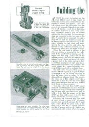
easier and results in a far stronger structure,<br />
with no bolts or rivets <strong>to</strong> work<br />
loose from vibration.<br />
If you have the welding done outside,<br />
be sure <strong>to</strong> cut, drill and fit all parts beforehand.<br />
It's smart <strong>to</strong> clamp them up in<br />
a trial assembly. Scrape paint off the tiller<br />
head where welds are <strong>to</strong> be made. Remove<br />
the chain case and gasket so that<br />
welding heat will not damage the latter.<br />
Wheels. Some commercial tillers have<br />
no wheels. But wheels give easier control<br />
of working depth, and facilitate moving<br />
the machine, especially over paved areas.<br />
You can buy 10" rubber-tired wheels<br />
with a 1½" tread for less than two dollars<br />
apiece, or a metal-tired type made for<br />
wheeled garden <strong>to</strong>ols for even less. For<br />
10" wheels, weld the shaft hangers in<strong>to</strong><br />
the braces as shown in the drawing. For<br />
other sizes, locate them so that the engine<br />
will be level when the bot<strong>to</strong>m of the<br />
tiller housing is about 1" beneath the<br />
soil. With the tines on a hard surface,<br />
the engine will slant forward. (As some<br />
will stall in this position when the fuel<br />
is low, it is important <strong>to</strong> have the engine<br />
nearly level in the working position.)<br />
The drawing on the facing page shows<br />
the axle turned down and threaded at<br />
one end. You can, instead, use a shaft<br />
collar at both ends, and so avoid machining.<br />
Be sure <strong>to</strong> use the felt seals<br />
shown if your wheels have ball bearings,<br />
<strong>to</strong> keep grit out of them.<br />
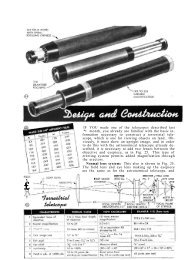
The power train. It takes considerable<br />
<strong>to</strong>rque <strong>to</strong> spin the tined shaft; an<br />
over-all reduction of about 1:16 is required<br />
with a 1¾-horsepower engine.<br />
The reduction built in<strong>to</strong> the tiller unit<br />
has a ratio of about 1:1.5. With an 8"<br />
pulley on the countershaft, the V-belt<br />
drive from the au<strong>to</strong>matic clutch of the<br />
engine shown gives a 1:4.4 reduction.<br />
A 10-<strong>to</strong>oth sprocket on the other end of<br />
the countershaft drives the 24-<strong>to</strong>oth<br />
sprocket on the tiller head at a 1:2.4<br />
ratio. Multiplying all the figures on both<br />
sides of the colon shows the over-all<br />
ratio <strong>to</strong> be 1:15.84.<br />
If your engine does not have a centrifugal<br />
clutch, you can install one or rig<br />
a belt-tightening idler controlled by a<br />
flexible cable. This is cheaper, but the<br />
centrifugal clutch is handier, giving you<br />
full control by use of throttle alone.<br />
Mounting the countershaft. A 3/16"<br />
steel plate is mounted on the <strong>to</strong>w-bar<br />
legs with long bolts and spacers. Cut the<br />
spacers from 3/8" pipe, taking care <strong>to</strong> get<br />
them all the same length. The bearings<br />
are bronze-bushed pillow blocks. Slots<br />
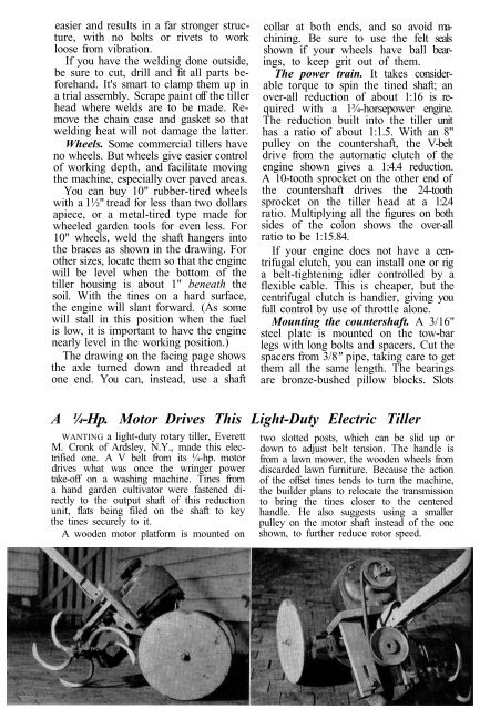
A ¼-Hp. Mo<strong>to</strong>r Drives This Light-Duty Electric <strong>Tiller</strong><br />
WANTING a light-duty rotary tiller, Everett<br />
M. Cronk of Ardsley, N.Y., made this electrified<br />
one. A V belt from its ¼-hp. mo<strong>to</strong>r<br />
drives what was once the wringer power<br />
take-off on a washing machine. Tines from<br />
a hand garden cultiva<strong>to</strong>r were fastened directly<br />
<strong>to</strong> the output shaft of this reduction<br />
unit, flats being filed on the shaft <strong>to</strong> key<br />
the tines securely <strong>to</strong> it.<br />
A wooden mo<strong>to</strong>r platform is mounted on<br />
two slotted posts, which can be slid up or<br />
down <strong>to</strong> adjust belt tension. The handle is<br />
from a lawn mower, the wooden wheels from<br />
discarded lawn furniture. Because the action<br />
of the offset tines tends <strong>to</strong> turn the machine,<br />
the builder plans <strong>to</strong> relocate the transmission<br />
<strong>to</strong> bring the tines closer <strong>to</strong> the centered<br />
handle. He also suggests using a smaller<br />
pulley on the mo<strong>to</strong>r shaft instead of the one<br />
shown, <strong>to</strong> further reduce ro<strong>to</strong>r speed.