How to Build a Rotary Tiller - Vintage Projects
How to Build a Rotary Tiller - Vintage Projects
How to Build a Rotary Tiller - Vintage Projects

Create successful ePaper yourself
Turn your PDF publications into a flip-book with our unique Google optimized e-Paper software.
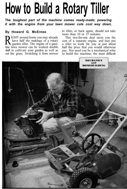
<strong>How</strong> <strong>to</strong> <strong>Build</strong> a <strong>Rotary</strong> <strong>Tiller</strong><br />
The <strong>to</strong>ughest part of the machine comes ready-made; powering<br />
it with the engine from your lawn mower cuts cost way down.<br />
By <strong>How</strong>ard G. McEntee<br />
RIGHT around home you may already<br />
have half the makings of a rotary<br />
garden tiller. The engine of a gasoline<br />
lawn mower can be worked double<br />
shift <strong>to</strong> cultivate your garden as well as<br />
cut the grass. Switching it from mower<br />
<strong>to</strong> tiller, or back again, should not take<br />
more than 10 or 15 minutes.<br />
This two-for-one deal saves you the<br />
cost of a separate engine, and may put<br />
a tiller <strong>to</strong> work for you at just about<br />
half the price that you would otherwise<br />
pay. Nor need you be a mechanical whiz<br />
<strong>to</strong> build the machine; the most difficult
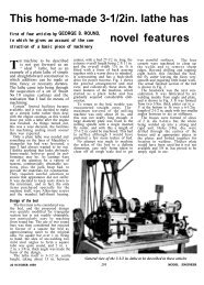
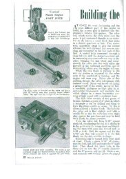
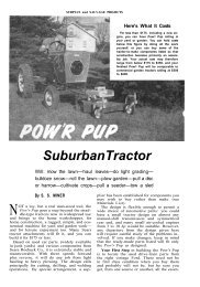
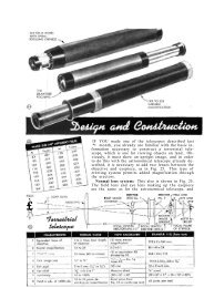
<strong>Tiller</strong> ro<strong>to</strong>r is driven by a chain from the countershaft<br />
PURCHASED TILLER and H-shaped <strong>to</strong>w bar are<br />
shown shaded in the drawing below. Pieces of<br />
angle iron are welded on <strong>to</strong> support the engine,<br />
wheels and countershaft. Adjust chain tension<br />
<strong>to</strong> leave ½" of slack as at right. If slots do not<br />
give enough adjustment, put washers under the<br />
spacers. Adjust V-belt tension by moving the<br />
engine backward or forward on its mounts.<br />
176 POPULAR SCIENCE
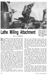
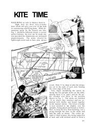
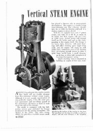
Housing and rock guard protect the user<br />
BOXLIKE TILLER HOUSING has a reduction<br />
unit with a 24-<strong>to</strong>oth sprocket<br />
mounted on its side. In the pho<strong>to</strong><br />
above, the <strong>to</strong>w bar, crosspieces and<br />
braces have been welded on, but<br />
countershaft is not yet in place. A<br />
hinged rock guard (at left in above<br />
pho<strong>to</strong>) shields the user from flying<br />
dirt and s<strong>to</strong>nes. The machine propels<br />
itself; effort is required only <strong>to</strong> hold<br />
it back or guide it over the ground.<br />
parts of it are available already made up.<br />
These are the tiller-head components—<br />
the shaft and tines that stir up the<br />
ground. A national mail-order house sells<br />
a 12" head as an accessory for a small<br />
garden trac<strong>to</strong>r.* Costing about $37, it is<br />
a well-made, neatly housed unit with<br />
hardened tines, good bearings, a built-in<br />
chain reduction and a rock guard. The<br />
tines are replaceable.<br />
If your mower engine has a centrifugal<br />
clutch and you put l½"-wide wheels on<br />
the tiller, the <strong>to</strong>tal parts cost will run<br />
about $52. (The tiller shown cost more<br />
because it has heavy-duty 2½" wheels.<br />
These make it easier <strong>to</strong> handle in soft<br />
soil, but are by no means a must.) Welding<br />
will run four or five dollars if you<br />
don't do it yourself, but will still leave<br />
the <strong>to</strong>tal cost well below that of a comparable<br />
commercial machine.<br />
Use all the pieces. With the tiller<br />
head you get a drive chain and an H-<br />
shaped <strong>to</strong>w bar for coupling <strong>to</strong> the trac<strong>to</strong>r<br />
you haven't got. Both will be useful.<br />
A boxlike angle-iron frame, <strong>to</strong> which<br />
the <strong>to</strong>w bar is meant <strong>to</strong> be bolted, is<br />
*Various attachments of this kind can be adapted. The drawings<br />
and construction methods described relate <strong>to</strong> Montgomery<br />
Ward's rotary-tiller attachment No. 87-5086 for the Til-Trac<br />
garden trac<strong>to</strong>r. Semi-pneumatic 10"-by-1.75" wheels are available<br />
from various mail-order dealers at about $1.65 each.<br />
welded a<strong>to</strong>p the tiller housing. The first<br />
thing <strong>to</strong> do is "unweld" this. Make centerpunch<br />
marks along the weld beads, the<br />
diameter of a 3/16" drill apart. Run a<br />
drill that size in at 45°, just <strong>to</strong> the surface<br />
of the housing. Then use a diamondtip<br />
cold chisel <strong>to</strong> cut through between<br />
the holes. Discard this frame.<br />
Cut a piece of 1½" angle iron <strong>to</strong> span<br />
the full width of the housing, long enough<br />
<strong>to</strong> be welded <strong>to</strong> the ends as well as <strong>to</strong> the<br />
<strong>to</strong>p. At one end, cut the vertical flange<br />
at a slant <strong>to</strong> clear the countershaft pulley.<br />
Drill the <strong>to</strong>p of the H frame for bolts<br />
<strong>to</strong> hold the countershaft mount. In the<br />
vertical flange of one frame leg, drill a<br />
hole for a handle bolt. The other handle<br />
mount is a 2" length of 1½" angle welded<br />
at the end of the housing.<br />
The front crosspiece, a 15" length of<br />
angle, projects past the H frame on one<br />
side <strong>to</strong> line up with the housing.<br />
Check your engine. This front crosspiece<br />
and the crossbar of the H frame<br />
form the engine mounts. The slots shown<br />
fit a Model 6 Briggs and Strat<strong>to</strong>n engine;<br />
for others, minor changes may be needed.<br />
By careful fitting and the use of extra<br />
brackets you could bolt the parts<br />
<strong>to</strong>gether. But welding makes the job<br />
FEBRUARY 1956 177
easier and results in a far stronger structure,<br />
with no bolts or rivets <strong>to</strong> work<br />
loose from vibration.<br />
If you have the welding done outside,<br />
be sure <strong>to</strong> cut, drill and fit all parts beforehand.<br />
It's smart <strong>to</strong> clamp them up in<br />
a trial assembly. Scrape paint off the tiller<br />
head where welds are <strong>to</strong> be made. Remove<br />
the chain case and gasket so that<br />
welding heat will not damage the latter.<br />
Wheels. Some commercial tillers have<br />
no wheels. But wheels give easier control<br />
of working depth, and facilitate moving<br />
the machine, especially over paved areas.<br />
You can buy 10" rubber-tired wheels<br />
with a 1½" tread for less than two dollars<br />
apiece, or a metal-tired type made for<br />
wheeled garden <strong>to</strong>ols for even less. For<br />
10" wheels, weld the shaft hangers in<strong>to</strong><br />
the braces as shown in the drawing. For<br />
other sizes, locate them so that the engine<br />
will be level when the bot<strong>to</strong>m of the<br />
tiller housing is about 1" beneath the<br />
soil. With the tines on a hard surface,<br />
the engine will slant forward. (As some<br />
will stall in this position when the fuel<br />
is low, it is important <strong>to</strong> have the engine<br />
nearly level in the working position.)<br />
The drawing on the facing page shows<br />
the axle turned down and threaded at<br />
one end. You can, instead, use a shaft<br />
collar at both ends, and so avoid machining.<br />
Be sure <strong>to</strong> use the felt seals<br />
shown if your wheels have ball bearings,<br />
<strong>to</strong> keep grit out of them.<br />
The power train. It takes considerable<br />
<strong>to</strong>rque <strong>to</strong> spin the tined shaft; an<br />
over-all reduction of about 1:16 is required<br />
with a 1¾-horsepower engine.<br />
The reduction built in<strong>to</strong> the tiller unit<br />
has a ratio of about 1:1.5. With an 8"<br />
pulley on the countershaft, the V-belt<br />
drive from the au<strong>to</strong>matic clutch of the<br />
engine shown gives a 1:4.4 reduction.<br />
A 10-<strong>to</strong>oth sprocket on the other end of<br />
the countershaft drives the 24-<strong>to</strong>oth<br />
sprocket on the tiller head at a 1:2.4<br />
ratio. Multiplying all the figures on both<br />
sides of the colon shows the over-all<br />
ratio <strong>to</strong> be 1:15.84.<br />
If your engine does not have a centrifugal<br />
clutch, you can install one or rig<br />
a belt-tightening idler controlled by a<br />
flexible cable. This is cheaper, but the<br />
centrifugal clutch is handier, giving you<br />
full control by use of throttle alone.<br />
Mounting the countershaft. A 3/16"<br />
steel plate is mounted on the <strong>to</strong>w-bar<br />
legs with long bolts and spacers. Cut the<br />
spacers from 3/8" pipe, taking care <strong>to</strong> get<br />
them all the same length. The bearings<br />
are bronze-bushed pillow blocks. Slots<br />
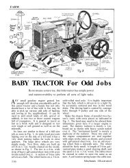
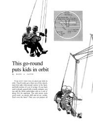
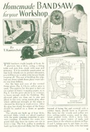
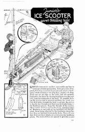
A ¼-Hp. Mo<strong>to</strong>r Drives This Light-Duty Electric <strong>Tiller</strong><br />
WANTING a light-duty rotary tiller, Everett<br />
M. Cronk of Ardsley, N.Y., made this electrified<br />
one. A V belt from its ¼-hp. mo<strong>to</strong>r<br />
drives what was once the wringer power<br />
take-off on a washing machine. Tines from<br />
a hand garden cultiva<strong>to</strong>r were fastened directly<br />
<strong>to</strong> the output shaft of this reduction<br />
unit, flats being filed on the shaft <strong>to</strong> key<br />
the tines securely <strong>to</strong> it.<br />
A wooden mo<strong>to</strong>r platform is mounted on<br />
two slotted posts, which can be slid up or<br />
down <strong>to</strong> adjust belt tension. The handle is<br />
from a lawn mower, the wooden wheels from<br />
discarded lawn furniture. Because the action<br />
of the offset tines tends <strong>to</strong> turn the machine,<br />
the builder plans <strong>to</strong> relocate the transmission<br />
<strong>to</strong> bring the tines closer <strong>to</strong> the centered<br />
handle. He also suggests using a smaller<br />
pulley on the mo<strong>to</strong>r shaft instead of the one<br />
shown, <strong>to</strong> further reduce ro<strong>to</strong>r speed.
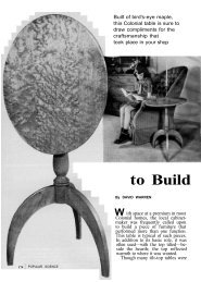
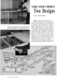
Wheels can be put inside for cultivating close-set rows<br />
WHEELS ARE HELD ON either with a collar at<br />
each axle end, or with a collar at one end and<br />
a nut at the other, as in the drawing at right.<br />
Cut dust seals from 1/8"-thick soft felt. For<br />
narrow-row cultivation, use a 15" axle, a spacer<br />
<strong>to</strong> fit between the wheels when they are inside<br />
the engine-support frame (above right) and<br />
felt seals on both sides of the wheel hubs.
for the mounting bolts allow these <strong>to</strong> be<br />
slid forward or back <strong>to</strong> adjust chain<br />
tension. Make sure that the shaft turns<br />
freely after all the bolts are pulled tight.<br />
The sprocket is best held on the countershaft<br />
with a taper pin. A setscrew<br />
will secure the pulley provided you drill<br />
a dimple in the shaft for it <strong>to</strong> seat in.<br />
Both for your own safety and <strong>to</strong> keep<br />
sticks and gravel out of the chain, a<br />
guard should be fitted. Cut one flange<br />
off 1" angle iron where it is <strong>to</strong> be bent <strong>to</strong><br />
a radius, as shown in the drawing on<br />
page 176. Use flathead bolts, with the<br />
heads countersunk inside the guard, <strong>to</strong><br />
join the ends and attach mounting brackets,<br />
one above, two at the lower end.<br />
Handle is brazed up. Cut ¾" electric<br />
conduit for the handle parts. Remove<br />
the zinc coating with abrasive cloth<br />
where the brazed joints must be made.<br />
Flatten the lower ends before drilling<br />
them for the 5/16" mounting bolts.<br />
The bracing fork consists of two pieces<br />
of 5/16" rod bent, threaded and brazed<br />
<strong>to</strong> a 3/16" plate. This is clamped under<br />
one engine-head bolt. With a nut on each<br />
side of the handle crossbar, the fork can<br />
FURROWING GUIDE, provided with tiller head,<br />
can be set <strong>to</strong> hold tines at desired tilling depth,<br />
or it can be reversed with the hook forward as<br />
above. In this position it holds the machine<br />
back for deep cultivating or plowing.<br />
be adjusted <strong>to</strong> raise or lower the handle<br />
<strong>to</strong> convenient working height. Bolt the<br />
throttle control within easy reach and slip<br />
bicycle handgrips on the <strong>to</strong>p bar. END<br />
FEBRUARY 1956 179