MAGGIS
MAGGIS
MAGGIS

Create successful ePaper yourself
Turn your PDF publications into a flip-book with our unique Google optimized e-Paper software.
THE 3G UMTS CAMERA<br />
<strong>MAGGIS</strong><br />
AUTOMATIC VIDEOCALL ON ALARM TRIGGER<br />
INSTRUCTIONS FOR USE<br />
1
Index<br />
Introduction 4<br />
Preliminary settings 6<br />
Turning on the device 6<br />
Inserting the USIM card 7<br />
Installation 8<br />
Suggestions for installation 8<br />
Fastening cable glands 8<br />
Fastening the bracket 9<br />
Fastening the camera to the bracket 10<br />
Terminal box wires and cabling 11<br />
Administrator management 11<br />
Administrator management and alarm calls 11<br />
Activation 12<br />
Connection the Charger 12<br />
Activating Video Services 15<br />
Advanced functions for the limited access mode 18<br />
<strong>MAGGIS</strong> Management 18<br />
Problem solving 21<br />
Important safety information 24<br />
General precautions 24<br />
Precautions for the battery and the adaptor 24<br />
Third party equipment 24<br />
Precautions for repairs 24<br />
Warranty Statement 25<br />
Technical Characteristics 26<br />
3
Introduction<br />
The following sections supply detailed information on the device.<br />
Introduction<br />
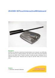
<strong>MAGGIS</strong> is the first video camera which allows you to listen to and see what is happening –<br />
even in the dark - where it is installed with a simple video call from a UMTS video-phone.<br />
<strong>MAGGIS</strong> is quickly installed, easy to use and supports the UMTS network.<br />
Figure 1<br />
Lid<br />
Figure 2<br />
4
Introduction<br />
Figure 3<br />
5
Preliminary settings<br />
Turning on the device<br />
The camera can be switched on/off using the Power Supply Switch (see figure 3).<br />
<br />
To turn on or switch off <strong>MAGGIS</strong> move the switch from the “OFF” to the “ON” position<br />
or vice versa with the aid of a tool (see Figure 4).<br />
Figure 4<br />
6
Installation<br />
Inserting the USIM card<br />
<br />
<br />
<br />
<br />
A USIM card must be inserted into the device before it can be used, disabling its<br />
PIN code using a video phone.<br />
Check to ensure that the device is switched off and the AC adaptor is unplugged before<br />
inserting or removing the USIM card.<br />
The device will not function properly unless a USIM is inserted. In this case, the device<br />
will note an anomaly and a red light will appear on the LED Network and BATTERY<br />
(LED position: see figure 3) lights.<br />
The USIM slot is shown in figure 3. Insert the USIM card into the slot in the direction of<br />
the arrow. Remember to lock the USIM card after it is inserted by pushing the USIM<br />
locking device (see figure 5).<br />
Figure 5<br />
Note 1: Check to ensure that the USIM card has been inserted as illustrated in the figure.<br />
Note 2: Take care when inserting the USIM card, since the metal contacts on the USIM<br />
card can be easily damaged/scratched.<br />
Move the device in the direction of the<br />
arrow to lock the USIM card<br />
7
Installation<br />
Suggestions for installing the device<br />
<br />
<br />
<br />
<br />
<br />
Do not position the device in front of light sources (to avoid overexposure).<br />
Do not place any objects within a 1 meter radius of the internal visual angle of the device<br />
(images could be unintelligible).<br />
Do not position the device in a basement; it may not have network coverage.<br />
Do not cover the device’s video camera with an object during a video call (image quality<br />
may be compromised).<br />
Do not cover the device with objects containing metallic materials (signal quality may be<br />
compromised)<br />
Fastening the cable glands<br />
Figure 6<br />
8
Installation<br />
Fastening the bracket<br />
Figure 7<br />
9
Installation<br />
Fastening the camera<br />
to the bracket<br />
Figure 8<br />
Insert the nut in the<br />
space indicated in the<br />
drawing<br />
10
Installation<br />
Figure 9<br />
Terminal box wires and cabling<br />
0 12V 24V<br />
Heater<br />
Connection<br />
12Vcc or<br />
24Vac<br />
ALARM NC<br />
Connection<br />
Activating alarm<br />
calls<br />
Administrator management<br />
Administrator management and alarm calls<br />
The administrator – the person authorised to send configuration commands – is defined when<br />
the first video call to <strong>MAGGIS</strong> is made.<br />
When asked for a PIN number, enter the code found inside the bag stored in the device’s box.<br />
<strong>MAGGIS</strong> will call the administrator number during an alarm.<br />
11
Activation<br />
Connecting the Charger<br />
Insert the charger into the device in the direction of the arrow.<br />
Figure 10<br />
<br />
<br />
<br />
The Battery and Network lights on the device will turn red and flash rapidly (once every<br />
second) on an off during this first phase.<br />
Once the device registers that a charger has been inserted, the Battery light will come on.<br />
Battery status is described in figure 11 below.<br />
If the Battery light is red and flashes rapidly (once every second), it is out of charge. The<br />
battery takes approximately 30 minutes to charge up to its minimum operative level. Do<br />
not switch on the device if the battery is below its minimum operative level. If the battery<br />
light is on and flashing slowly (once every 3 seconds), the battery has been charged up to<br />
its minimum operative level.<br />
12
Activation<br />
Low<br />
RED<br />
Approximately 30 minutes<br />
to reach its minimum<br />
Operative level.<br />
FULL<br />
GREEN<br />
Approximately 4 hours to<br />
charge the battery up to a 90%<br />
capacity.<br />
Figure 11<br />
Battery status is described in the figure below (Figure 12).<br />
Battery light<br />
Very low<br />
RED<br />
Flashing rapidly (once every<br />
second)<br />
Low<br />
RED<br />
Flashing slowly (once every<br />
3 seconds)<br />
Medium<br />
YELLOW<br />
Flashing slowly (once every<br />
3 seconds)<br />
Full<br />
GREEN<br />
Not flashing<br />
Figure 12<br />
13
Activation<br />
<br />
<br />
<br />
The Network light will display a yellow light while the device searches for the UMTS<br />
network. This will then turn green and start flashing rapidly. The light will show battery<br />
levels after it has measured battery capacity. Network status is described in figure 13<br />
below.<br />
Once the device is connected to the network, the Network light will turn green and stop<br />
flashing.<br />
The device and all its functions are ready for use once the Network light turns green and<br />
the Battery light displays the level charge the battery has.<br />
Network light<br />
Good coverage /<br />
ready for use<br />
GREEN<br />
Not flashing<br />
During a Video<br />
call<br />
GREEN<br />
Flashing slowly (once every 3 seconds)<br />
Searching for the<br />
UMTS network<br />
YELLOW<br />
Flashing rapidly (once every seond)<br />
Out of service<br />
RED<br />
Both the Battery and Network light<br />
flash rapidly (once every second)<br />
Figure 13<br />
14
Attivazione Activation<br />
Activating the service<br />
<br />
Follow the instructions below to carry out the authentication procedure and activate video<br />
services.<br />
1) Video call <strong>MAGGIS</strong> with a video phone (dial the number of the device and activate<br />
the video call function from the video phone).<br />
2) A request will be made for a four (4) digit PIN code – found inside the device’s box.<br />
This will activate the transmission of images recorded by <strong>MAGGIS</strong>. The graphic in<br />
figure 14 will be displayed on your video phone.<br />
Figure 14<br />
3) Enter the PIN code by pressing the appropriate keys on your video phone. The<br />
graphic will change as you enter the PIN code. Please see the graphics shown in<br />
figures 15 to 17.<br />
Figure 15 Figure 16<br />
Figure 17<br />
15
Activation<br />
4) The device will then check the PIN code you entered. If the PIN code is correct, the<br />
graphic shown in Figure 18 will be displayed and that telephone number will be<br />
added to the device's memory (saved in a list of authorisations). The number used to<br />
make the first call to the device to establish a connection will be given the title of<br />
Administrator. If the PIN code is incorrect, the graphic shown in Figure 19 will be<br />
displayed and you will be given two more chances to enter the correct PIN code.<br />
Figure 18 Figure 19<br />
Note 1: The device will automatically disconnect a video call after 3 failed attempts to<br />
enter a PIN code, or after 1 minute.<br />
5) Once authenticated, the device will emit a sound to indicate that the video call has<br />
begun. Images recorded by <strong>MAGGIS</strong> can then be seen in real time.<br />
6) A PIN code must only be entered the first time the video call services are used.<br />
Once the number is added to the device's memory (List of Authorisations), it will<br />
always be permitted to connect to the device without the need to enter a PIN code.<br />
<br />
Disconnecting a video call:<br />
1) The user interrupts the connection of the video call from their video phone.<br />
2) The transmission of images recorded by <strong>MAGGIS</strong> is interrupted and the video call<br />
is disconnected.<br />
16
Activation<br />
Note 2: for safety reasons, the device always keeps a "List of Authorisations” stored in its<br />
internal memory where it saves information on authorised users.<br />
Only authorised users can use the services supplied by the device.<br />
The List of Authorisations can save information on up to 20 users. To be<br />
automatically added to the List of Authorisations, users must video call the device<br />
and enter correctly enter its PIN code. The first user on the list is the<br />
Administrator, who is authorised to configure the device by using SMS<br />
commands (please see the “<strong>MAGGIS</strong> management" section).<br />
Note 3: IF a video call is made to the device by a user not on the list – once 20 authorised<br />
users are listed and stored in the memory - the device will not recognise the caller,<br />
who will be unable to connect to the device.<br />
Warning 1: do not conceal your number while making a video call. The device will be<br />
unable to recognise the caller and will refuse the connection.<br />
Note 4: <strong>MAGGIS</strong> video services can be used even when the charger is disconnected. A<br />
video call will not be connected if battery capacity is insufficient (below 5%).<br />
Note 5: Video calls will be terminated if battery capacity has reached its minimum<br />
operative level (below 5%) and an authorised user calls and activates the<br />
device. The user will receive a warning that the battery is low before the call is<br />
terminated.<br />
Note 6: <strong>MAGGIS</strong> must be placed in a fixed position. To ensure that video call quality<br />
remains high, place the device in an appropriate position checking the network<br />
light - which shows the strength of the radio signal received by the device.<br />
Please see figure 13 for Network light status.<br />
17
Advanced functions for the limited access mode<br />
<strong>MAGGIS</strong> management<br />
Only the administrator - the first user saved on the device’s List of Authorisations –<br />
is authorised to change settings on the List of Authorisations.<br />
<br />
<br />
The Administrator can send commands to the device using SMS text messages.<br />
These can be used to change a number of settings on the List of Authorisations.<br />
The Administrator can use 6 different commands. They are: 1) Change the number<br />
of users saved on the List of Authorisations; 2) Change the Administrator's number; 3)<br />
Delete an authorised user; 4) Delete all authorised users; 5) Enter a number as an<br />
authorised user; 6) change the PIN code.<br />
Note: SMS COMMANDS are not caps sensitive.<br />
Warning: Should the Administrator change his/her video phone – for example following<br />
an MNP request – we recommend the new number be saved as Administrator. For any<br />
problems connected to an Administrator number change, please contact Customer Services.<br />
1) To change the number of users saved in the List of<br />
Authorisations<br />
• The List of Authorisations has been programmed to save 20 authorised users. The<br />
Administrator can change this predefined number to any number between 1 and 20<br />
by sending an SMS message to the device containing the following text:<br />
#modlist*[NUMBER]#[PIN]#<br />
Note: [NUMBER] must be a number between 1 and 20.<br />
[PIN] is the correct 4 digit pin code<br />
For example, the following message can be sent to limit the List of Authorisations to only<br />
3 users: #modlist*3#1234#<br />
Warning: All information on excess users will be automatically deleted once the<br />
number of users saved in the List of Authorisations is changed, if<br />
the new number is lower than the previous one.<br />
• No more than 20 users can be saved on the List of Authorisations<br />
18
Advanced functions for the limited access mode<br />
2) To change the Administrator’s telephone number:<br />
• The Administrator’s telephone number can be changed by sending an SMS text<br />
message to the device from the Administrator’s phone.<br />
Warning: The Administrator’s number can only be changed five times. Please<br />
contact Customer Services if the number needs to be changed again after<br />
five changes.<br />
• To change this number, the Administrator must send an SMS message to the device<br />
containing the following text:<br />
#changead*[OLDNUMBER]*[NEWNUMBER]#[PIN]#<br />
Note: [OLDNUMER] is the Administrator’s old number.<br />
[NEWNUMBER] is the new Administrator number.<br />
[PIN] is the correct 4 digit pin code<br />
For example if:<br />
(OLD NUMBER) = +3931111111<br />
(NEW NUMBER) = +3932222222<br />
(PIN) = 1234<br />
SMS Command: #changead*+393931111111*+393932222222#1234#<br />
3) To delete a specific authorised user<br />
A specific authorised user can be deleted by sending an SMS message to the device<br />
from the Administrator phone containing the following text:<br />
#del*[NUMBER]#[PIN]#<br />
Note: [NUMBER] is the user number you want to delete.<br />
[PIN] is the correct 4 digit pin code<br />
For example, send the following command to delete the number +3931234567 from<br />
the List of Authorisations: #del*+393931234567#1234#<br />
Warning: The Administrator number cannot be deleted by sending this command.<br />
4) To delete all authorised users<br />
All authorised users can be deleted from the List of Authorisations by sending an<br />
SMS message to the device from the Administrator phone containing the following<br />
text:<br />
#deluser#[PIN]#<br />
Warning: [PIN] is the correct 4 digit pin code<br />
For example: #deluser#1234#<br />
Warning: All users will be deleted from the List of Authorisations once the<br />
device has received the command, with the exception of the<br />
Administrator.<br />
19
Advanced functions for the limited access mode<br />
5) To enter new numbers as authorised users<br />
A specific authorised user can be added to the List of Authorisations by sending an<br />
SMS message to the device from the Administrator phone containing the following<br />
text:<br />
#add*[NUMBER]#[PIN]#<br />
Note: [NUMBER] is the number you want to add to the List of Authorisations.<br />
[PIN] is the correct 4 digit pin code<br />
For example, if you want to add the number +3937654321 to the List as an<br />
authorised user:<br />
#add#+393937654321#1234#<br />
Warning: The [NUMBER] will not be added to the List of Authorisations once the<br />
number of numbers saved on the list has reached its limit. The SMS<br />
message will be ignored if the [NUMBER] is already found on the<br />
list.<br />
6) To change the PIN code<br />
The PIN code can be changed by sending an SMS message to the device from the<br />
Administrator phone containing the following text:<br />
#pin*[NEW_PIN]*#[PIN] #<br />
[NEW PIN] is the 4 digit number you want to use as a PIN code.<br />
[PIN] is the 4 digit number you want to change.<br />
For example send the following message to change PIN 1234 to a new PIN 0987:<br />
#PIN*0987#1234#<br />
The Table 1-1 below contains a description of all Administrator SMS commands.<br />
SMS Command<br />
#modlist*[NUMBER]#[PIN]#<br />
Example: #modlist*3#1234#<br />
#changead*[OLDNUMBER]*[NEWNUMBER]#[PIN]#<br />
Example: #changead*+393931111111*+393932222222#1234#<br />
#del*[NUMBER]#[PIN]#<br />
Example: #del*+393931234567#1234#<br />
#deluser#[PIN]#<br />
Example: #deluser#1234#<br />
#add*[NUMBER]#[PIN]#<br />
Example: #add*+393937654321#1234#<br />
#pin*[NEW_PIN]#[PIN] #<br />
Example: #pin*0987#1234#<br />
Description<br />
Use to change the number of users saved on<br />
the List of Authorisations<br />
Use to change the telephone number<br />
belonging to the Administrator<br />
Use to delete a specific authorised user<br />
Use to delete all authorised users<br />
Use to enter new numbers as authorised users<br />
Use to change the PIN code<br />
20
Problem Solving<br />
A list is provided below describing a series of situations<br />
which may take place while the device is in use. Please<br />
check the list before contacting Customer Services.<br />
1. Restarting the device (resetting procedure)<br />
<br />
The device can be restarted by pressing the reset button and keeping it pressed for at least<br />
5 seconds.<br />
Note: The device will be automatically restarted by pressing the reset button. All users will be<br />
deleted from the List of Authorisations, with the exception of the Administrator and the<br />
PIN code.<br />
2. The Network Light is off<br />
Check that the USIM card has been inserted into the USIM slot and that is correctly<br />
locked.<br />
If the USIM card has been inserted and locked correctly and the Network Light is still<br />
off, press the reset button for 5 seconds to restart the device.<br />
Note: All users will be deleted from the List of Authorisations once the device is reset, with<br />
the exception of the Administrator.<br />
Please contact Customer Services if the device still fails to function properly after it has<br />
been reset.<br />
3. The Battery Light is red continues to flash on and off<br />
<br />
<br />
<br />
<br />
Check that the USIM card has been inserted into the USIM slot and that is correctly<br />
locked.<br />
If the Network Light stays red and continues to flash on and off, move the device to<br />
another position because the radio signal is insufficient in that particular position.<br />
Using your video phone, check for UMTS network coverage.<br />
If, the light has not changed to yellow or green after you have tried a number of different<br />
positions, press the reset button for 5 seconds to restart the device.<br />
Note: All users will be deleted from the List of Authorisations once the device is reset, with<br />
the exception of the Administrator.<br />
Please contact Customer Services if the device still fails to function properly after it has<br />
been reset.<br />
21
Problem Solving<br />
4. The Battery Light is red and continues to flash on and off<br />
Check that the USIM card has been inserted into the USIM slot and that is correctly<br />
locked.<br />
Check that the charger is properly connected to the device and that it has been connected<br />
to a 220v AC power supply for at least 3 hours<br />
If the charger has been connected to the device in a correct manner and if it has been<br />
connected to a 220V AC power supply for at least 3 hours and the Battery Light is still<br />
red and continues flashing on and off, press the reset button for 5 seconds to restart the<br />
device.<br />
Note: All users will be deleted from the List of Authorisations once the device is reset, with<br />
the exception of the Administrator.<br />
Please contact Customer Services if the device still fails to function properly after it has<br />
been reset.<br />
5. The Battery and Network lights are red and remain on<br />
<br />
<br />
<br />
If both the Network and Battery Lights are red and remain on (but are not flashing),<br />
perform the procedure to switch off/restart the device.<br />
To switch off the device:<br />
The battery switch is found in the lower part of the device. Move the battery switch<br />
from the “ON” to the “OFF” position with the aid of a tool to switch off the device<br />
completely.<br />
Move the battery switch from the “OFF” to the “ON” position to switch on the<br />
device.<br />
Please contact Customer Services if, after carrying out the procedure to switch off/restart<br />
the device, both the Network and Battery Lights are red and remain on (but are not<br />
flashing).<br />
6. SMS command errors when configuring the device<br />
<br />
The device will ignore all SMS text messages it receives containing errors and syntax<br />
mistakes. It will also ignore all SMS text messages sent by users without Administrator<br />
privileges. If you have made a mistake, just send a new, valid SMS text message.<br />
22
Problem Solving<br />
7. The device does not switch on when I move the Power switch<br />
<br />
<br />
<br />
First of all, switch off the device, remove and reconnect the charger; then attempt to<br />
switch on the device again. If the charger is not connected to the device, charge up the<br />
battery completely and try again.<br />
If the device still does not switch on and the battery is completely charged, carry out the<br />
switch off/restart procedure.<br />
To switch off/restart the device:<br />
• Move the battery switch from the “ON” to the “OFF” position with the aid of a tool<br />
to switch off the device completely.<br />
• Move the battery switch from the “OFF” to the “ON” position to switch on the<br />
device.<br />
<br />
Please contact Customer Services if the device still fails to function properly after it has<br />
been reset.<br />
23
Important security information<br />
Please read the following information before using <strong>MAGGIS</strong>.<br />
Carefully read the following precautions in order to reduce the risk of personal injury from<br />
electric shocks, fires and to reduce the risk of damaging the equipment.<br />
General precautions<br />
Precautions for the battery and for the adaptor<br />
• Never connect or disconnect the AC current adaptor with wet hands. Connecting or disconnecting the<br />
AC current adaptor from a power supply with wet hands may cause an electric shock.<br />
• Never place the AC current adaptor on wooden surfaces (or any other surface which could be<br />
damaged by heat) when in use because its temperature rises when it is on. Always place it on materials<br />
which isolate heat.<br />
• Never cover the AC adaptor with an object when in use and never place it next to a heat source. An<br />
excessive increase in temperature could prejudice its functioning.<br />
• Do not dismantle or attempt to repair the AC adaptor and never change its plugs or wires. You could<br />
run the risk of receiving an electric shock.<br />
• Do not dismantle or modify the battery.<br />
• Stop using the device if you have noted anomalous temperatures, smells, staining or deformations or if<br />
it behaves in an abnormal manner when in use, while charging or when stored.<br />
A continued use of the <strong>MAGGIS</strong> video camera under any of these conditions could lead to the<br />
combustion of battery liquids or could cause the battery to crack.<br />
• Do not touch any liquids leaking out from a damaged battery for any reason. This liquid may cause<br />
serious lesions if it comes into contact with the skin or eyes. If the liquid comes into contact with the<br />
eyes rinse, thoroughly with clean water and contact a doctor immediately.<br />
If the liquid comes into contact with clothing or skin, wash immediately with clean water.<br />
• Always use the cloths supplied in the package to clean the camera’s lenses and always use a wet or<br />
antistatic cloth to clean the device. Do not use chemical detergents or abrasives as these could damage<br />
the device.<br />
Third party equipment<br />
The use of equipment, AC adaptors or third party accessories which have not been<br />
manufactured or authorised by POLITEC invalidate the product's warranty and prejudice the<br />
safety of the device itself.<br />
Precautions for repairs<br />
No part of the device, battery or charger ma be repaired by the user. Do not attempt to<br />
dismantle or repair these parts on your own as it may lead to fires, electric shocks and faults.<br />
Always contact an authorised customer services centre for repairs and substitutions.<br />
24
Technical Waranty Statement Characteristics<br />
This item has been manufactured by Politec Srl.<br />
Politec hereby guarantees that the product is free from design, working and material defects for the entire duration<br />
of the Warranty, under the following terms and conditions:<br />
1. The product cannot be guaranteed to function if it is employed outside the UMTS 3 network in Italy.<br />
a. The Warranty is applicable for 24 months as of the date of purchase of the product from an authorised<br />
Politec retailer.<br />
b. To receive assistance under the warranty, customers must present the Product coupled with its invoice or<br />
original purchase receipt to an authorised Politec customer services centre.<br />
c. Politec shall repair or substitute the Product, or any faulty part, at is own exclusive discretion throughout the<br />
warranty period. Politec or the authorised customer service centre shall carry out all repairs and substitutions<br />
only after Politec itself has verified that the product is covered by a Warranty. Repairs or substitutions may<br />
lead to a remanufactured - and nevertheless equivalent from a functional point of view - part of the Product<br />
being employed. Politec shall return the Product if repaired, or an equivalent Product in good functioning<br />
condition, to the Customer.<br />
d. Should Politec repair or substitute a Product, the Product shall maintain its warranty for the remaining<br />
duration of the Warranty period or for three (3) months as of the date of the repair, depending on which of<br />
the two periods is longer.<br />
e. Politec is not responsible for damages to or losses of any eventual, programs, data or removable storage<br />
systems.<br />
f. The Warranty shall not be applicable if:<br />
a) The fault is due to unsuitable or inaccurate use with respect to the instructions contained in the<br />
instructions manual or due to use outside of the maximum nominal power consented, or due to corrosion,<br />
oxidation, changes or unauthorised connections, unauthorised opening of the machine or unauthorised<br />
repairs to the machine, repairs carried out with unauthorised spare parts, inappropriate use, incorrect<br />
installation of the Product, incidents, natural events, damages due to chemical products or other<br />
damages outside any control which may reasonably be exercised by Politec (including, but in no way<br />
limited to, wearing on parts such as the battery for example which, because of its nature, has a limited<br />
life span, or broken or damaged antennas).<br />
b) Should the client fail to notify a fault to an authorised Politec Customer Services centre within two (2)<br />
months as of the appearance of the fault itself during the warranty period.<br />
c) Should the product be brought to a Politec customer service centre after the expiry of the Warranty<br />
period.<br />
d) Should the product’s serial number, accessory date code, or IMEI number have been removed, deleted,<br />
scratched, changed or should these nevertheless be illegible.<br />
e) Should the fault have been caused by employing (or connecting) the Product with an accessory not<br />
supplied or approved by Politec, or should it have been employed in a manner difference from its<br />
provided uses.<br />
g. All transport costs with respect to the shipment of the faulty Product and/or delivery of the Product by the<br />
authorised Politec customer services centre shall be borne by the customer.<br />
NO EXPLICIT, WRITTEN OR ORAL WARRANTIES ARE IN EXISTENCE OTHER THAN THE PRESENT<br />
WARRANTY. ALL IMPLICIT, INCLUDED WARRANTIES - WITHOUT LIMITATIONS – REGARDING THE<br />
MARKETABILITY OR SUITABILITY OF THE PRODUCT FOR A GIVEN PURPOSE ARE LIMITED TO THE<br />
DURATION OF THE PRESENT WARRANTY. POLITEC SHALL IN NO WAY BE RESPONSIBLE FOR<br />
ACCIDENTAL OR CONSEQUENTIAL DAMAGERS OR ANY NATURE, INCLUDING, BUT IN NO WAY<br />
LIMITED TO, LOSS OF PROFITS OR TRADE, WITHIN THE MAXIMUM LEGAL CONSENTED LIMITS<br />
UNDER WHICH THESE DAMAGES MAY BE DECLINED.<br />
25
Alarm video call<br />
Heater<br />
Technology<br />
Weight and size<br />
Camera<br />
Connectivity<br />
Microphone<br />
Video calls<br />
Messages<br />
Battery<br />
Privacy<br />
Security<br />
Other<br />
characteristics<br />
- Through the NC contact<br />
- Automatic power supply thermostat<br />
12 Vcc/24Vac<br />
- Temperature range –25° +70° C°<br />
- UMTS<br />
- LxWxH: 200x80x80<br />
- CCD100k pixel, 352x288<br />
- Field angle 58” diagonal,46”<br />
horizontal, 38” vertical<br />
- USB port for SW updates<br />
- Sensitivity greater – 40 dB<br />
- Answers and makes video calls from<br />
every operator<br />
- Receives SMS text configuration<br />
messages<br />
- 2200mAh for an autonomy of 330 hours in<br />
standby, 4 hours of video calls, 3,2 hours of<br />
video calls during the night.<br />
- Limits incoming video calls to up to 20<br />
numbers, not contemporary<br />
- Access is granted to see the images by<br />
entering a PIN code<br />
- LED battery light, cover for<br />
malfunctions<br />
- Reset button<br />
- Wall support bracket<br />
26