Improvement methods of reconstruction process in digital holography
Improvement methods of reconstruction process in digital holography
Improvement methods of reconstruction process in digital holography

Create successful ePaper yourself
Turn your PDF publications into a flip-book with our unique Google optimized e-Paper software.
Contributed paper<br />
OPTO-ELECTRONICS REVIEW 11(3), 203–209 (2003)<br />
<strong>Improvement</strong> <strong>methods</strong> <strong>of</strong> <strong>reconstruction</strong> <strong>process</strong> <strong>in</strong> <strong>digital</strong> <strong>holography</strong><br />
S. PAŒKO * and R. JÓWICKI<br />
Institute <strong>of</strong> Micromechanics and Photonics, Warsaw University <strong>of</strong> Technology<br />
8 Boboli Str., 02-525 Warsaw, Poland<br />
Problems <strong>of</strong> quality improvement <strong>in</strong> holographic images and a <strong>reconstruction</strong> time reduction are discussed. The convolution<br />
and Fresnel approaches are presented. For both <strong>methods</strong> the algorithm improvement is proposed. Bas<strong>in</strong>g on a special transmittance<br />
function calculation, a computation time significantly decreases. For the Fresnel approximation, an<br />
autocorrelation factor from the reconstructed image is removed. The presented ideas are illustrated by exemplary images for<br />
each step <strong>of</strong> computation. Advantages and disadvantages <strong>of</strong> the <strong>methods</strong> are discussed.<br />
Keywords: <strong>digital</strong> <strong>holography</strong>, convolution approach, response function, image filtration.<br />
1. Introduction<br />
Simplicity <strong>of</strong> the registration <strong>process</strong>, no wet <strong>process</strong><strong>in</strong>g<br />
and the possibility <strong>of</strong> immediate re<strong>process</strong><strong>in</strong>g <strong>of</strong> stored data<br />
are the ma<strong>in</strong> reasons <strong>of</strong> cont<strong>in</strong>uously <strong>in</strong>creas<strong>in</strong>g <strong>in</strong>terest <strong>in</strong><br />
<strong>digital</strong> <strong>holography</strong> (DH). The data are stored <strong>in</strong> a<br />
mass-<strong>digital</strong> memory and they can be used <strong>in</strong> any place<br />
equipped with a computer work<strong>in</strong>g <strong>in</strong> a communication<br />
network. Assum<strong>in</strong>g the number <strong>of</strong> CCD matrix pixels to be<br />
1024´1024, one hologram without any compression is registered<br />
us<strong>in</strong>g one MB file. Therefore, a commercially available<br />
hard disk may accommodate many thousands <strong>of</strong> holograms.<br />
The objects registered can be located <strong>in</strong> not easily<br />
accessible areas, and the object registration can be accomplished<br />
fully automatically. The data could be distributed<br />
simultaneously to other computers to estimate various object<br />
features.<br />
Digital record<strong>in</strong>g <strong>of</strong> holograms by a CCD camera is<br />
correct as long as the sampl<strong>in</strong>g theorem is fulfilled. This<br />
means that every <strong>in</strong>terferometric fr<strong>in</strong>ge <strong>of</strong> the hologram has<br />
to be sampled at least by two pixels <strong>of</strong> the CCD matrix.<br />
Therefore the angle between the object and reference<br />
waves must be sufficiently small. In practice, the above<br />
condition implies registration <strong>of</strong> small objects or objects located<br />
sufficiently far from the hologram plane. These restrictions<br />
do not allow for some applications <strong>of</strong> <strong>digital</strong> <strong>holography</strong><br />
<strong>in</strong> multimedia techniques. However, a rapid progress<br />
observed <strong>in</strong> the semiconductor technology permits to<br />
express optimistic forecasts for near, or even further future.<br />
The <strong>reconstruction</strong> <strong>process</strong> <strong>in</strong> DH is fully <strong>digital</strong> and no<br />
optic arrangement is needed. All computer calculations can<br />
be performed bas<strong>in</strong>g on the Rayleigh-Sommerfeld (R-S)<br />
diffraction formula [1]. However, us<strong>in</strong>g this formula directly<br />
results <strong>in</strong> time consum<strong>in</strong>g procedures. It is better to<br />
* e-mail: s.pasko@mchtr.pw.edu.pl<br />
use its simplified versions reduc<strong>in</strong>g to Fresnel approximation<br />
or convolution approaches [2]. In the majority <strong>of</strong> applications,<br />
the first method is more popular due to its fast calculations.<br />
Unfortunately, variable pixel dimension at the<br />
hologram plane and the noise <strong>in</strong>troduced by the<br />
zero-diffraction order represent ma<strong>in</strong> disadvantageous features<br />
<strong>of</strong> the Fresnel approximation method [3]. In the paper,<br />
some image improvements are considered reduc<strong>in</strong>g the<br />
noise sources <strong>in</strong> the holographic image. Subtract<strong>in</strong>g the average<br />
value <strong>of</strong> the holographic <strong>in</strong>tensity distribution from<br />
the holographic fr<strong>in</strong>ge image to elim<strong>in</strong>ate the zero-order<br />
diffraction beam is the simplest and fastest method to improve<br />
the image quality [3]. The successive subtraction <strong>of</strong><br />
<strong>in</strong>tensity distributions registered, separately, by the object<br />
and reference beams is similar method to the one mentioned<br />
above but it can be effective under the stable experimental<br />
conditions [4]. Insert<strong>in</strong>g, adequately, a mask <strong>in</strong>to<br />
the image spectrum, low spatial frequencies <strong>in</strong>clud<strong>in</strong>g the<br />
zero diffraction order can be elim<strong>in</strong>ated. The mask transmittance<br />
should be a cont<strong>in</strong>uous function to avoid undesirable<br />
diffraction <strong>in</strong>tensity oscillations <strong>in</strong> the holographic image<br />
[5]. The suppression <strong>of</strong> the conjugate image is a more<br />
complex operation. Locat<strong>in</strong>g a diaphragm between the object<br />
be<strong>in</strong>g registered and the hologram plane is one <strong>of</strong> the<br />
solutions [6]. First, dur<strong>in</strong>g the <strong>reconstruction</strong> procedure, the<br />
field distribution at the diaphragm plane is determ<strong>in</strong>ed.<br />
This field, truncated by a virtual diaphragm <strong>of</strong> proper dimensions,<br />
allows f<strong>in</strong>d<strong>in</strong>g the field distribution at the hologram<br />
plane. It is used at the f<strong>in</strong>al stage to determ<strong>in</strong>e the image<br />
field distribution. Such an approach suppresses the<br />
higher spatial frequencies <strong>of</strong> the object and removes the<br />
conjugate image. The convolution approach gives the image<br />
with constant pixel dimensions [2]. However, due to<br />
the limited reconstructed image area and more complex algorithm,<br />
with comparison to the Fresnel approximation<br />
method <strong>in</strong>duc<strong>in</strong>g time-consum<strong>in</strong>g procedures, this ap-<br />
Opto-Electron. Rev., 11, no. 3, 2003 S. Paœko 203
<strong>Improvement</strong> <strong>methods</strong> <strong>of</strong> <strong>reconstruction</strong> <strong>process</strong> <strong>in</strong> <strong>digital</strong> <strong>holography</strong><br />
proach is applied less frequently. In the paper, a method decreas<strong>in</strong>g<br />
the calculation time is proposed.<br />
2. Method <strong>of</strong> noise reduction <strong>in</strong> the central part<br />
<strong>of</strong> holographic images<br />
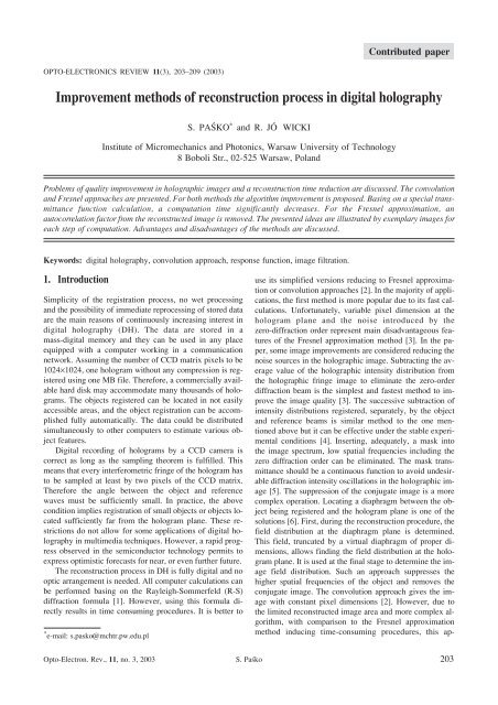
Subtract<strong>in</strong>g the average value <strong>of</strong> the <strong>in</strong>tensity distribution<br />
from the holographic fr<strong>in</strong>ge image, the zero-order diffraction<br />
beam is removed. Afterwards, us<strong>in</strong>g Fourier transformation<br />
<strong>of</strong> the rema<strong>in</strong><strong>in</strong>g <strong>in</strong>tensity distribution the spectrum<br />
is received. It is presented <strong>in</strong> Fig. 1(a) <strong>in</strong> a pictorial manner,<br />
and <strong>in</strong> Fig. 1(b) for a laboratory realised hologram.<br />
Black central part <strong>in</strong> Fig. 1(b) results from the above<br />
mentioned subtractive pre-<strong>process</strong><strong>in</strong>g. However, three<br />
components real image, conjugate image, and a residuum<br />
from zero-order diffraction beam are present. The boundaries<br />
between the constitutive areas are never precisely<br />
well def<strong>in</strong>ed. Therefore it is difficult to elaborate an automatic<br />
program to separate the area <strong>of</strong> the demanded real<br />
image.<br />
We propose to make use <strong>of</strong> a symmetry property <strong>of</strong> the<br />
auto-correlation component with respect to the spectrum<br />
centre.<br />
Let h(x,y) be the <strong>in</strong>tensity distribution at the hologram<br />
plane after subtract<strong>in</strong>g its average value. Fourier transform<br />
u(m,n) <strong>of</strong> the <strong>in</strong>tensity h(x,y) described by the follow<strong>in</strong>g<br />
equation<br />
-1<br />
u( m, n) = FFT [ h( x, y)]<br />
, (1)<br />
is a base to improve the holographic image quality. In general,<br />
the quantities m, n are the coord<strong>in</strong>ates <strong>in</strong> the Fourier<br />
doma<strong>in</strong> <strong>of</strong> the hologram <strong>in</strong>tensity distribution, moreover,<br />
they have not be treated as physical parameters. It is worth<br />
emphasiz<strong>in</strong>g that <strong>in</strong> the case <strong>of</strong> Fourier hologram with an<br />
object situated at <strong>in</strong>f<strong>in</strong>ity these quantities take the role <strong>of</strong><br />
angular coord<strong>in</strong>ates.<br />
For the every spectrum column m, the centre <strong>of</strong> the <strong>in</strong>tensity<br />
distribution and its shift with respect to the spectrum<br />
centre are determ<strong>in</strong>ed by the follow<strong>in</strong>g relation<br />
nG<br />
=<br />
å<br />
umnn ( , )<br />
N<br />
åumn<br />
( , ) , (2)<br />
N<br />
where N is the number <strong>of</strong> the samples <strong>in</strong> the every column.<br />
The distribution <strong>of</strong> the gravity centre vs. the column number,<br />
calculated for an exemplary object, is presented <strong>in</strong> Fig. 2.<br />
Choos<strong>in</strong>g a level value <strong>of</strong> |n G –N 0 | denot<strong>in</strong>g by d <strong>in</strong><br />
Fig. 2 where N 0 =N 0 /2, the columns with the gravity centres<br />
below the chosen level are removed, what is described<br />
<strong>in</strong> mathematical form by the follow<strong>in</strong>g equation<br />
( G 0 )<br />
" m Î á0, M Ù n - N < d Þ u( mn , ) = 0, (3)<br />
In consequence, majority <strong>of</strong> the spectrum related to the<br />
auto-correlation component is removed and the procedure<br />
result is presented <strong>in</strong> Fig. 3(a). The result received for laboratory<br />
hologram is shown <strong>in</strong> Fig. 3(b).<br />
Some non-zero columns, visible <strong>in</strong> the central part <strong>of</strong><br />
Fig. 3(b) have no significant <strong>in</strong>fluence on the image quality<br />
due to the low spatial frequency filtration. In the next step,<br />
the conjugate image area is removed putt<strong>in</strong>g zero for all<br />
columns located at the conjugate image side, what is presented<br />
<strong>in</strong> Figs. 4(a) and 4(b).<br />
From the observer po<strong>in</strong>t <strong>of</strong> view it is more convenient<br />
to displace the spectrum gravity centre denoted by n c and<br />
m c , where<br />
mC<br />
åå<br />
åå<br />
umnm ( , )<br />
umnm ( , )<br />
N M<br />
N M<br />
= nC<br />
=<br />
ååumn<br />
( , ) , ååumn<br />
( , ) , (4)<br />
N M<br />
N M<br />
Fig. 1. Spatial spectrum <strong>of</strong> a typical hologram. Pictorial (a) and real (b) cases.<br />
204 Opto-Electron. Rev., 11, no. 3, 2003 © 2003 COSiW SEP, Warsaw
Contributed paper<br />
Fig. 2. Gravity centre distribution for a chosen object.<br />
Fig. 3. Spatial spectrum after zero-order beam filtration. Pictorial (a) and real (b) cases.<br />
Fig. 4. Spatial spectrum after filtrat<strong>in</strong>g the zero-order beam and the conjugate image area.<br />
Opto-Electron. Rev., 11, no. 3, 2003 S. Paœko 205
<strong>Improvement</strong> <strong>methods</strong> <strong>of</strong> <strong>reconstruction</strong> <strong>process</strong> <strong>in</strong> <strong>digital</strong> <strong>holography</strong><br />
Fig. 5. Spectrum centr<strong>in</strong>g. Pictorial (a) and real (b) cases.<br />
to the image centre. The new image is given by u’<br />
u¢ ( mn , ) = u( m- mC, n -nC). (5)<br />
The result <strong>of</strong> mentioned operation is presented <strong>in</strong> Figs.<br />
5(a) and 5(b) for the pictorial and real cases, respectively.<br />
F<strong>in</strong>ally the <strong>in</strong>verse Fourier transformation<br />
-1<br />
h ¢ (, x y) = FFT [ u ¢ ( m, n)]<br />
, (6)<br />
is applied to receive the complex distribution h (x,y) atthe<br />
hologram plane with reduced noises. This distribution is a<br />
base to calculate a reconstructed image [7].<br />
To show the method effectiveness, two holographic image<br />
<strong>reconstruction</strong>s from the same hologram were accomplished.<br />
First image, Fig. 6(a), was obta<strong>in</strong>ed by remov<strong>in</strong>g a<br />
constant component from the hologram <strong>in</strong>tensity. A dist<strong>in</strong>ct<br />
noise can be seen around the image <strong>of</strong> the object registered.<br />
Apply<strong>in</strong>g the method described above, the image becomes<br />
free <strong>of</strong> noises [Fig. 6(b)].<br />
3. Convolution approach – performance<br />
improvement<br />
As it was mentioned above, the convolution approach is<br />
one <strong>of</strong> the basic <strong>methods</strong> <strong>of</strong> <strong>digital</strong> hologram <strong>reconstruction</strong>.<br />
In a simplified version, it can be described by follow<strong>in</strong>g<br />
expression<br />
-<br />
b ¢ = FFT 1 { FFT{ h × r} FFT{ g}, (7)<br />
where<br />
ì2ip<br />
2 2 2 2 2 ü<br />
exp í d¢ + ( m- M 2) Dx<br />
+ ( n - N 2)<br />
Dh<br />
ý<br />
î l<br />
þ<br />
gmn ( , ) =<br />
, (8)<br />
2<br />
d¢ + ( m- M 2) 2 Dx<br />
2 + ( n - N 2)<br />
2 Dh<br />
2<br />
Fig. 6. Reconstructed images before (a) and after proposed filtration (b).<br />
206 Opto-Electron. Rev., 11, no. 3, 2003 © 2003 COSiW SEP, Warsaw
Contributed paper<br />
h and r represent the <strong>in</strong>tensity and wave front distribution at<br />
the hologram plane, respectively [2]. Kreis <strong>in</strong> Ref. 2 has<br />
proposed a modification <strong>of</strong> this method. The Fourier transform<br />
<strong>of</strong> g(m,n) was substituted by G(m’,n’), the analytically<br />
calculated Fourier transform <strong>of</strong> g(m,n), i.e.,<br />
where<br />
-<br />
b ¢ = FFT 1 { FFT{ h × r} × G}, (9)<br />
3.1. New algorithm<br />
Our aim is to propose the solution to improve the <strong>reconstruction</strong><br />
us<strong>in</strong>g the convolution method with less time required.<br />
At the beg<strong>in</strong>n<strong>in</strong>g, let us assume that the aperture <strong>of</strong><br />
the CCD camera has a rectangular shape and it is possible<br />
to represent it by a superposition <strong>of</strong> two <strong>in</strong>f<strong>in</strong>ite longitud<strong>in</strong>al<br />
apertures, perpendicular to each other. The transfer<br />
function <strong>of</strong> the <strong>in</strong>f<strong>in</strong>ite longitud<strong>in</strong>al aperture is the same for<br />
ì<br />
ï<br />
ï 2pid<br />
¢<br />
Gmn ( , ) = expí<br />
ï<br />
l<br />
ï<br />
î<br />
æ<br />
m<br />
M 2 2 ö<br />
2<br />
2 Dx<br />
æ<br />
2<br />
N<br />
ç + ÷ 2 Dh öü<br />
l<br />
l ç n + ÷ ï<br />
è 2d<br />
¢ l ø è 2 d¢<br />
l øï<br />
1 -<br />
-<br />
2 2<br />
2 2 ý. (10)<br />
M Dx<br />
N Dh<br />
ï<br />
ï<br />
þ<br />
It is the easiest approach to f<strong>in</strong>d the G(m,n) term but it<br />
requires square root and exponential function for each<br />
pixel calculation. These mathematical operations require<br />
relatively a lot <strong>of</strong> time <strong>of</strong> the co-<strong>process</strong>or. Because dur<strong>in</strong>g<br />
the computation three Fourier transforms are used, the<br />
convolution approach is much slower than the Fresnel approximation<br />
approach. On the other hand it <strong>of</strong>fers the reconstructed<br />
image usually free <strong>of</strong> the zero order beam.<br />
The zero order appears <strong>in</strong> the image when a number <strong>of</strong><br />
pixels is very high and the angle between the object and<br />
reference beams is small enough. Another <strong>in</strong>terest<strong>in</strong>g feature<br />
<strong>of</strong> the method is the pixel size constancy <strong>in</strong> the reconstructed<br />
images. The pixel size <strong>in</strong> this case is <strong>in</strong>dependent<br />
<strong>of</strong> the holographic arrangement parameters and is equal to<br />
the size <strong>of</strong> CCD pixel. This feature causes also some <strong>in</strong>convenience,<br />
because dur<strong>in</strong>g the <strong>reconstruction</strong> <strong>process</strong><br />
only a fragment <strong>of</strong> the registered object which corresponds<br />
to the size <strong>of</strong> CCD matrix, is restored. In order to<br />
obta<strong>in</strong> a whole image, one has to compose it from several<br />
sub-images calculated dur<strong>in</strong>g sequential <strong>reconstruction</strong><br />
<strong>process</strong>es.<br />
The image obta<strong>in</strong>ed suffers from the existence <strong>of</strong> discont<strong>in</strong>uity<br />
located at place <strong>of</strong> sub-images connection. This<br />
fault can lead to errors especially when the phase for holographic<br />
<strong>in</strong>terferometry is calculated. In order to avoid these<br />
errors, it is proposed to stretch the size <strong>of</strong> hologram artificially<br />
for example from 1024´1024 to 2048´2048, for <strong>in</strong>stance,<br />
by add<strong>in</strong>g zeros around the orig<strong>in</strong>al image. In result,<br />
the <strong>reconstruction</strong> <strong>of</strong> a real object area <strong>of</strong> size<br />
2048´2048 times the CCD pixel size is obta<strong>in</strong>ed. Unfortunately,<br />
calculations <strong>in</strong> this case need a lot <strong>of</strong> time due to <strong>in</strong>creas<strong>in</strong>g<br />
the object size so, quicker algorithms are badly<br />
needed. Consider<strong>in</strong>g a formula given by Eq. (7) it is possible<br />
to <strong>in</strong>crease the speed <strong>of</strong> image calculation, for <strong>in</strong>stance<br />
by <strong>in</strong>troduc<strong>in</strong>g hardware FFT calculation or by modify<strong>in</strong>g<br />
the function g(m,n), represent<strong>in</strong>g the impulse response <strong>of</strong><br />
the optical arrangement.<br />
each perpendicular cross-section. The impulse response <strong>of</strong><br />
such an aperture can be calculated for one cross-section<br />
only and duplicated for the other ones. Because there are<br />
two perpendicular apertures considered, the same operation<br />
must be repeated for the other one. Procedures needed to<br />
obta<strong>in</strong> full <strong>in</strong>formation about the transfer function are presented<br />
below together with the figures illustrat<strong>in</strong>g their performance.<br />
Generally, the calculation <strong>process</strong> can be divided <strong>in</strong>to<br />
three parts. First, the pulse response function <strong>of</strong> s<strong>in</strong>gle l<strong>in</strong>es<br />
<strong>in</strong> both directions must be computed. They are given by<br />
ì2ip<br />
2 2 2 ü<br />
exp í d¢ + ( m-<br />
M 2)<br />
Dx<br />
ý<br />
gm ( m ) 1 î l<br />
þ<br />
=<br />
, (11)<br />
il<br />
2 2 2<br />
d¢ + ( m-<br />
M 2)<br />
Dx<br />
ì2ip<br />
2 2 2 ü<br />
exp í d¢ + ( n - N 2)<br />
Dh<br />
ý<br />
gn () 1 î l<br />
þ<br />
n =<br />
. (12)<br />
il<br />
2 2 2<br />
d¢ + ( n - N 2)<br />
Dh<br />
Next the Fourier transform is calculated. In consequence,<br />
one-dimensional spectrum <strong>of</strong> the response function<br />
is obta<strong>in</strong>ed (see Fig. 7)<br />
G( m¢ ) = FFT( g m( m)), G( n ¢ ) = FFT( g n( n))<br />
. (13)<br />
In follow<strong>in</strong>g, the results <strong>of</strong> 1D operation are stretched to<br />
2D ones by duplicat<strong>in</strong>g the l<strong>in</strong>es (Fig. 8). Two separate data<br />
blocks are created <strong>in</strong> which the results for “x” and “y” direction,<br />
respectively, are stored<br />
G1( m¢ , n¢ ) = G( m¢ ), G2( m¢ , n¢ ) = G( n¢ ). (14)<br />
Last operation can be named as the f<strong>in</strong>al composition<br />
(Fig. 9). It consists <strong>of</strong> 2D multiplication <strong>of</strong> G 1 and G 2 . Be-<br />
Opto-Electron. Rev., 11, no. 3, 2003 S. Paœko 207
<strong>Improvement</strong> <strong>methods</strong> <strong>of</strong> <strong>reconstruction</strong> <strong>process</strong> <strong>in</strong> <strong>digital</strong> <strong>holography</strong><br />
Fig. 7. Image <strong>of</strong> one l<strong>in</strong>e G(k’): (a) <strong>in</strong>tensity and (b) phase.<br />
Fig. 8. View after duplicat<strong>in</strong>g the l<strong>in</strong>es <strong>of</strong> G: (a) <strong>in</strong>tensity and (b) phase.<br />
cause G 2 represents the data along the “y” axis, therefore <strong>in</strong><br />
the multiplication conjugated values <strong>of</strong> G 2 must be used<br />
M N<br />
G( m¢ , n ¢ ) = P P G1( m¢ , n ¢ ) conj( G2 ( m¢ , n ¢ )). (15)<br />
m= 1 n=<br />
1<br />
The algorithm presented is approximately four times<br />
faster than the algorithm proposed by Kreis. This feature<br />
results from reduc<strong>in</strong>g the number <strong>of</strong> called procedures calculat<strong>in</strong>g<br />
square root and exponential. In consequence, the<br />
number <strong>of</strong> float<strong>in</strong>g po<strong>in</strong>t operations is six times smaller.<br />
However, larger number <strong>of</strong> <strong>process</strong>or operations due to the<br />
array transfer limits the speed <strong>of</strong> computation. Maximum<br />
error <strong>in</strong> the <strong>in</strong>tensity <strong>reconstruction</strong> <strong>in</strong>troduced by this approach<br />
is approximately 1%.<br />
Fig. 9. Fourier transform G(k’,l’) <strong>of</strong> the impulse response g(k,l): (a) <strong>in</strong>tensity and (b) phase.<br />
208 Opto-Electron. Rev., 11, no. 3, 2003 © 2003 COSiW SEP, Warsaw
Contributed paper<br />
Fig. 10. Reconstructed image <strong>of</strong> a screw composed <strong>of</strong> 4 subimages.<br />
Fig. 11. Image <strong>of</strong> a screw reconstructed by a modified procedure.<br />
3.2. Direct image <strong>reconstruction</strong><br />
Hav<strong>in</strong>g the algorithm with <strong>in</strong>creased speed one may consider<br />
to improve the <strong>process</strong> <strong>of</strong> full image <strong>reconstruction</strong><br />
us<strong>in</strong>g the convolution method. The conventional technique<br />
requires form<strong>in</strong>g the image from sub-images obta<strong>in</strong>ed upon<br />
<strong>reconstruction</strong> with shifted co-ord<strong>in</strong>ates <strong>in</strong> Eq.(8). The result<br />
<strong>of</strong> this procedure is <strong>of</strong>ten unsatisfactory due to significant<br />
errors at the borders <strong>of</strong> sub-images, as shown <strong>in</strong><br />
Fig. 10. We propose to apply the method which relies on<br />
artificial enlargement <strong>of</strong> size <strong>of</strong> hologram. In our case, its<br />
orig<strong>in</strong>al size <strong>of</strong> 1024 by 1024 pixels was changed to 2048<br />
by 2048. It gave the possibility to reconstruct the area that<br />
was four times larger and covered the whole image doma<strong>in</strong>.<br />
A restored image is free <strong>of</strong> disturbances encountered<br />
<strong>in</strong> the previous case as shown <strong>in</strong> Fig. 11. One essential disadvantage<br />
<strong>of</strong> this approach is its big memory requirement.<br />
If there are not enough memory resources, the computer<br />
starts procedure <strong>of</strong> data swapp<strong>in</strong>g with hard disc. The<br />
swapp<strong>in</strong>g <strong>process</strong> can slow down the computer considerably<br />
and the calculation lasts then very long.<br />
4. Conclusions<br />
Digital <strong>holography</strong> will become an attractive method to record<br />
and transform the images for multimedia techniques <strong>in</strong><br />
future. Clear, noiseless images transformed <strong>in</strong> real time are<br />
ma<strong>in</strong> requirements not fulfilled yet. The <strong>methods</strong> proposed <strong>in</strong><br />
the paper are aim<strong>in</strong>g at achiev<strong>in</strong>g this goal but the results received<br />
are far from moderate expectations yet. The availability<br />
<strong>of</strong> the CCD camera with high resolv<strong>in</strong>g power is one <strong>of</strong><br />
the most important factors facilitate the aim.<br />
Acknowledgements<br />
This work was supported by the State Committee for Scientific<br />
Research under the project 8T07D04621.<br />
References<br />
1. L.P. Jaros³awski and N.S. Merzljakow, “Methods <strong>of</strong> <strong>digital</strong><br />
<strong>holography</strong>”, Consultants Bureau, New York, 1980.<br />
2. T. Kreis and W. Jupner, “Pr<strong>in</strong>ciples <strong>of</strong> <strong>digital</strong> <strong>holography</strong>”,<br />
Proc. Fr<strong>in</strong>ge 97, 353–363 (1997).<br />
3. T. Kreis and W. Jupner, “Suppression <strong>of</strong> dc term <strong>in</strong> <strong>digital</strong><br />
<strong>holography</strong>”, Opt. Eng. 36, 2357–2360 (1997).<br />
4. S. Seebacher, W. Osten, and W. Juptner, “Measur<strong>in</strong>g shape<br />
and deformation <strong>of</strong> small objects us<strong>in</strong>g <strong>digital</strong> <strong>holography</strong>”,<br />
Proc. SPIE 3479, 104–115 (1998).<br />
5. E. Cuche, P. Marquet, and C. Depeurs<strong>in</strong>ge, “Spatial filter<strong>in</strong>g<br />
for zero-order and tw<strong>in</strong>-image elim<strong>in</strong>ation <strong>in</strong> <strong>digital</strong> <strong>of</strong>f-axis<br />
<strong>holography</strong>”, Appl. Optics 39, 4070–4075 (2000).<br />
6. G. Pedr<strong>in</strong>i, P. Fron<strong>in</strong>g, H. Fessler, and HJ. Tiziani, “In-l<strong>in</strong>e<br />
<strong>digital</strong> holographic <strong>in</strong>terferometry”, Appl. Optics 37,<br />
6262–6269 (1998).<br />
7. S. Paœko and R. JóŸwicki, “Novel Fourier approach to <strong>digital</strong><br />
<strong>holography</strong>”, Opto-Electron. Rev. 10, 89–95 (2002).<br />
Opto-Electron. Rev., 11, no. 3, 2003 S. Paœko 209
ANNOUNCEMENT and CALL FOR PAPERS<br />
Submit your abstract to this new European meet<strong>in</strong>g<br />
26–30 April 2004<br />
Strasbourg, France<br />
Science · Research · Eng<strong>in</strong>eer<strong>in</strong>g<br />
Technology · Applications · Commercialization<br />
Present your research and be a part <strong>of</strong> this unique European event. Photonics Europe will br<strong>in</strong>g together global<br />
leaders from all areas <strong>of</strong> optics/photonics research, development, and commercialization.<br />
Photonics Europe will address the toughest issues fac<strong>in</strong>g optical and photonics technology developers today.<br />
Present your research paper <strong>in</strong> these topical areas:<br />
· Lasers<br />
· Biophotonics<br />
· Optoelectronics<br />
· Nano-Photonics<br />
· Materials<br />
· Metrology<br />
· Sens<strong>in</strong>g<br />
· Micro-Optics<br />
· Packag<strong>in</strong>g<br />
· Micromach<strong>in</strong><strong>in</strong>g<br />
Plus:<br />
· Special Hot Topics Session<br />
Come to Strasbourg for science and eng<strong>in</strong>eer<strong>in</strong>g, but stay the week and enjoy the Photonics Hot Topics,<br />
15 cross-discipl<strong>in</strong>ary conferences, an extensive bus<strong>in</strong>ess program, a new European exhibition, and <strong>of</strong> course the<br />
superb Alsatian d<strong>in</strong><strong>in</strong>g, where new friends and new ideas are just a part <strong>of</strong> the menu.<br />
Plan now to participate and present your research.<br />
Conferences | spie@spie.org | Tel: +1 360 676 3290<br />
210 Opto-Electron. Rev., 11, no. 3, 2003 © 2003 COSiW SEP, Warsaw