USB Numeric Display Development Manual - Delcom Products Inc.
USB Numeric Display Development Manual - Delcom Products Inc.
USB Numeric Display Development Manual - Delcom Products Inc.

Create successful ePaper yourself
Turn your PDF publications into a flip-book with our unique Google optimized e-Paper software.
<strong>USB</strong> <strong>Numeric</strong> <strong>Display</strong><br />
<strong>Development</strong> <strong>Manual</strong><br />
<strong>Delcom</strong> Engineering<br />
200 William St. Suite 302<br />
Port Chester, NY<br />
10573<br />
914-934-5170<br />
914-934-5171 Fax<br />
www.delcom-eng.com<br />
Document Ver <strong>USB</strong>NDSPY 1.1 June 31, 2003
Contents<br />
1.0 Introduction<br />
2.0 Quick Start Up Guide<br />
3.0 Specifications<br />
3.1 OS Compatibility<br />
3.2 Mounting<br />
3.3 Mechanical Dimensions<br />
3.4 Electrical<br />
3.5 Visual Output<br />
3.6 Audio Output<br />
4.0 Features<br />
4.1 <strong>Numeric</strong> <strong>Display</strong><br />
4.2 Auditory Indicator<br />
5.0 Programming<br />
5.1 Programming Overview<br />
5.2 Programming with the DLL<br />
5.3 Programming with Direct Method<br />
5.4 Direct Methods Commands<br />
6.0 Disk Contents<br />
7.0 Release Notes<br />
8.0 Ordering Information<br />
9.0 Notes<br />
9.1 Using <strong>USB</strong> Extension Cables<br />
9.2 Using <strong>USB</strong> Hubs<br />
Appendix A – Related documents and websites
1.0 Introduction<br />
The <strong>USB</strong> <strong>Numeric</strong> <strong>Display</strong> visual and optional auditory signal device<br />
powered and activated via the <strong>USB</strong> port. The device has 4 to 8 seven<br />
segment LED digits. LED color is available in red and green. LED<br />
scan rate, flash rate and duty cycle are programmable. The optional<br />
auditory signal is produced by an piezo buzzer. Buzzer frequency,<br />
duty cycle and repeat count are all programmable. The device is selfpower<br />
from the <strong>USB</strong> bus and requires no additional hardware.<br />
2.0 Quick Start Up Guide<br />
To start using the <strong>USB</strong> <strong>Numeric</strong> <strong>Display</strong>, simply plug it in to an<br />
available <strong>USB</strong> port on your computer. All <strong>USB</strong> devices are “hot<br />
plugable” so you can plug it in with the computer on or off.<br />
Windows will automatically detect the new device and search for<br />
the required driver. If the driver is not already installed on your<br />
computer Windows will display “New hardware Found” dialog box<br />
and prompts you to enter the location of the <strong>USB</strong> driver. Place the<br />
<strong>USB</strong> <strong>Numeric</strong> <strong>Display</strong> distribution disk in the floppy drive and select<br />
that drive to install the driver. This procedure for loading the driver is<br />
only required once. Once the driver is loaded you can use one of the<br />
sample applications on the distribution disk to control the <strong>USB</strong><br />
<strong>Numeric</strong> <strong>Display</strong> device.<br />
If you have problems installing the driver please refer to “Loading<br />
Windows <strong>USB</strong> Drivers” applications note on the web site.<br />
For the latest driver and updates refer to the <strong>Delcom</strong> web site.
3.0 Specifications<br />
3.1 OS Compatibility<br />
The <strong>USB</strong> <strong>Numeric</strong> <strong>Display</strong> device is compatible with the following<br />
operating systems. Windows 98, ME, 2000, XP and MAC OSX.<br />
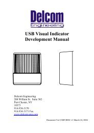
3.2 Mounting<br />
The <strong>USB</strong> <strong>Numeric</strong> <strong>Display</strong> can be purchased with or with out an<br />
enclosure. The dimension for the PCB and enclosure are shown<br />
below.<br />
3.2 Mechanical<br />
The <strong>USB</strong> <strong>Numeric</strong> <strong>Display</strong> dimensions, PCB only.<br />
1.50"<br />
0.15"<br />
0.00"<br />
0.00" 0.15"<br />
3.<br />
The <strong>USB</strong> <strong>Numeric</strong> <strong>Display</strong> dimensions with enclosure are 3.9” width,<br />
2.0” height and 0.8” deep.<br />
3.3 Electrical<br />
The <strong>USB</strong> Visual Indicator consumes 8mA when all LEDs and buzzer<br />
is off and 200ma maximum when all LEDs are on. The <strong>USB</strong> cable<br />
length is 2 meters (6 ½ Feet). {Also see 9.1}<br />
3.4 Visual Output<br />
The LEDs have a typical rating of 100,000 hours.<br />
3.5 Audio Output<br />
The audio signal is generated from a piezo buzzer producing 85 dB @<br />
2.4KHz with out the enclosure.
4.0 Features<br />
4.1 <strong>Numeric</strong> <strong>Display</strong><br />
The <strong>USB</strong> <strong>Numeric</strong> <strong>Display</strong> can be programmed in three modes. There<br />
are Raw, Hex and Ascii. In Raw data is sent directly to the seven<br />
segment Leds with out any conversion. See the Raw data table<br />
below. Raw mode allows the programmer to have complete control<br />
over each Led segment. This allow’s the to create custom characters.<br />
Valid values for Raw mode are 0-255 where 0 is all LEDs off.<br />
Hex mode allows the user to enter a number from 0 to 15. Values of<br />
10 through 15 are displayed as A,bC,d,E. Valid range is 0-15, any<br />
other value will show as a hyphen.<br />
Ascii mode allow the user to send Ascii character to the device. Valid<br />
Ascii characters are 0-9, A-F and a-f. Any other character will be<br />
displayed as a hyphen.<br />
When send data to the device the data length must be set to the correct<br />
number of digit that you what to display. All other digits greater than<br />
the length are turned off.<br />
The Led scan rate may be adjusted through software. The default is 10<br />
and the units are in 128us. Valid range is 1-255, where 255 is the<br />
slowest scan rate.<br />
The display can be programmer to flash. Valid flash values are from 0<br />
to 255, when zero equals flash off and 255 is the slowest flash rate.<br />
Flash in off by default.<br />
Each device can be configured as a 1 to 8 digit display. The default<br />
display value is 6. The display setup command can change the device<br />
from a 1 to 8 digit display. When less than 8 digits are used the<br />
unused scan lines can be used as general I/O.<br />
The decimal point has an separate command to control where the<br />
decimal point goes. Decimal point can also be controller direct in<br />
Raw mode.<br />
Table1 – Bit to Segment Relationship<br />
8 7 6 5 4 3 2 1(LSB)<br />
dp g f e d c b a
Table2 – Raw Data Standard Character Values<br />
Symbol Hex Dec Ascii<br />
0 0x00 0 48<br />
1 0x06 6 49<br />
2 0x5B 91 50<br />
3 0x4F 79 51<br />
4 0x66 102 52<br />
5 0x6D 109 53<br />
6 0x7D 125 54<br />
7 0x07 7 55<br />
8 0x7F 127 56<br />
9 0x67 103 57<br />
A 0x77 119 65<br />
B 0x7C 124 66<br />
C 0x39 57 67<br />
D 0x5E 94 68<br />
E 0x79 121 69<br />
F 0x71 113 70<br />
4.2 Auditory Indicator (Optional)<br />
The user can program the auditory indicator frequency, duty cycle and<br />
repeat value. The frequency is programmed by setting the buzzer’s<br />
frequency time variable, the units are in 256us. For example a desired<br />
buzzer frequency of 1KHz would yield a frequency value of around 4.<br />
The buzzer‘s ontime and offtime variables are used to program the<br />
duty cycle of the buzzer. These units are in 50ms. So if you wanted<br />
the buzzer to turn on and off every second you would program 10 for<br />
the ontime and offtime. The repeat value dictates what mode the<br />
buzzer will be in. If a value of zero is used for the repeat value then<br />
the buzzer will sound continuously at the frequency specified until the<br />
user turns it off. If a value of 255 is used then the buzzer will sound at<br />
the frequency and duty cycle specified until the user turns it off. If<br />
any other value is used the buzzer will sound at the frequency and<br />
duty cycle specified for the repeat value number of times.<br />
To increase the buzzer volume a small hole may be cut under the<br />
piezo buzzer in the plastic case.
5.0 Programming<br />
5.1 Programming Overview<br />
There are two ways to communicate to the <strong>USB</strong> device. They are the<br />
Direct Method and the DLL Method. The DLL method is the easier<br />
of the two to use. The DLL method adds slightly more processor<br />
overhead but relinquishes the programmer from having to deal with<br />
the low level commands of the <strong>USB</strong> device. The following sections<br />
describe how to communicate to the <strong>Delcom</strong> <strong>USB</strong> <strong>Numeric</strong> <strong>Display</strong><br />
device. Please use this document along with the sample code available<br />
on the distribution disk and <strong>Delcom</strong> web site.<br />
Requirements<br />
<strong>Delcom</strong> <strong>USB</strong> <strong>Numeric</strong> <strong>Display</strong> Device<br />
<strong>USB</strong> ready computer running Win98, ME, Win 2000, or XP.<br />
Microsoft Visual C++ version 4.0 or better, or equivalent 32 bit<br />
compiler for x86 based system, or Visual basic compiler.<br />
Knowledge of C/C++ or Visual basic.<br />
5.2 Programming with the DLL<br />
Please see the <strong>Delcom</strong>DLL documentation available on the<br />
distribution disk and website for more information. Below is a simple<br />
example in C using the <strong>Delcom</strong>DLL.<br />
#include "stdafx.h"<br />
#include "<strong>Delcom</strong>DLL.h"<br />
int main(int argc, char* argv[])<br />
{<br />
char DeviceName[MaxDeviceLen];<br />
HANDLE hUsb;<br />
<strong>Delcom</strong>GetNthDevice(<strong>USB</strong>NDSPY, 0, DeviceName); // get devicename<br />
hUsb = <strong>Delcom</strong>OpenDevice(DeviceName,0); // open device<br />
<strong>Delcom</strong><strong>Numeric</strong>Mode(hUsb,ON);<br />
// <strong>Display</strong> On<br />
<strong>Delcom</strong><strong>Numeric</strong>Auto(hUsb,1234.56); // Send Data<br />
<strong>Delcom</strong>CloseDevice(hUsb);<br />
// close device<br />
return(0);<br />
}<br />
5.3 Programming with Direct Method<br />
To communicate with <strong>USB</strong> <strong>Numeric</strong> <strong>Display</strong> Driver one must first<br />
enumerate the device. The enumeration of the device returns a device<br />
name. This device name is used to open the interface, using<br />
CreateFile(). Once you have the handle from CreateFile() you can<br />
use DeviceIOControl() to communicate to the <strong>USB</strong> Visual Signal<br />
Device and CloseHandle() to close it. To send commands to the <strong>USB</strong><br />
Visual Signal device, simply build a command packet and submit it<br />
using the DeviceIOControl function.
Device Enumeration:<br />
In order to communicate to the <strong>USB</strong> device one must first find its<br />
device name. The device name consists of a string of number<br />
representing a physical port plus the GUID (global unique identifier)<br />
for the device. In XP the PID (Product Identification Number) and<br />
the VID (Vendor Identification Number) are also include in this<br />
string. The device name can change each time you plug in an<br />
additional device or plug the device into a different <strong>USB</strong> port or hub<br />
on your computer system.<br />
The GUID for the <strong>Delcom</strong> <strong>USB</strong> <strong>Numeric</strong> <strong>Display</strong> device is<br />
{5BAFC627-C81C-4832-9AAA-C5A60B25715D}, and a typical<br />
complete device name looks like<br />
\\.\0000000000000012#{5BAFC627-C81C-4832-9AAA-C5A60B25715D}.<br />
Device Name Registry Method<br />
There are two ways to get the device name. The easiest method is to<br />
read the device name from the registry. When a <strong>USB</strong> <strong>Numeric</strong><br />
<strong>Display</strong> device is plugged in to your computer, the OS detects it and<br />
loads the driver. When this driver loads the device name is stored in<br />
the registry. Then the user just reads the name out of the registry.<br />
This method has one disadvantage. It can’t be used when more than<br />
one <strong>USB</strong> Visual Signal device is plugged in to your computer,<br />
because only the last device name will be recorded in the registry.<br />
To use the registry method simply open the registry key, query the<br />
value, and close the registry key. The registry key name is<br />
DeviceName and the path is<br />
HKEY_LOCAL_MACHINE\System\CurrentControlSet\Services\<strong>Delcom</strong>\<strong>USB</strong>NDSPY\Parameters\<br />
You can uses regedit.exe to find the entry. It is also a good place to<br />
copy the GUID from.
VB Registry Example<br />
Here is an example in Visual Basic on how to read the device name<br />
from the registry.<br />
DIM DeviceName as string<br />
DeviceName = GetRegValue(HKEY_LOCAL_MACHINE, _<br />
"System\CurrentControlSet\Services\<strong>Delcom</strong>\<strong>USB</strong>NDSPY\Parameters\",<br />
_<br />
"DeviceName")<br />
' GetRegValue - Gets the Key value in the registry given a registry key.<br />
Function GetRegValue(hKey As Long, lpszSubKey As String, szKey As String ) As<br />
String<br />
Dim phkResult As Long, lResult As Long<br />
Dim szBuffer As String, lBuffSize As Long<br />
'Create Buffer<br />
szBuffer = Space(255)<br />
lBuffSize = Len(szBuffer)<br />
' Allocate buffer space<br />
' Set the length<br />
RegOpenKeyEx hKey, lpszSubKey, 0, 1, phkResult<br />
handle to it<br />
'Open the Key, get a<br />
lResult = RegQueryValueEx(phkResult, szKey, 0, 0, szBuffer, lBuffSize) 'Query<br />
the value<br />
RegCloseKey phkResult<br />
If lResult = ERROR_SUCCESS Then<br />
GetRegValue = szBuffer<br />
End If<br />
Exit Function<br />
'Close the Key<br />
‘ return key value<br />
Device Name Enumeration Method<br />
The second method to get the device name is to use Windows<br />
device manager. To do this one calls a function in the setupapi.dll.<br />
Simply poll the device manger with the <strong>USB</strong> Visual Signal GUID for<br />
all the devices that match the GUID given. The device manager will<br />
return the device names for all the devices currently available on your<br />
system. This is the better way of getting the device name. It allows<br />
the user to use multiple devices on the same computer. The<br />
disadvantage is that it is a little more complicated.
C Enumeration Example<br />
Below is a C example using this enumeration method.<br />
Use the DEFINE_GUID macro to build the GUID.<br />
// {5BAFC627-C81C-4832-9AAA-C5A60B25715D}<br />
DEFINE_GUID(<strong>USB</strong>NDSPY_GUID,<br />
0x5bafc627, 0xc81c, 0x4832, 0x9a, 0xaa, 0xc5, 0xa6, 0xb,<br />
0x25, 0x71, 0x5d);<br />
This GUID is passed to SetupDiGetClassDevs(), which returns a<br />
handle to the device. The enumeration functions are found in the<br />
setupapi library.<br />
HDEVINFO hinfo = SetupDiGetClassDevs(&<strong>USB</strong>NDSPY_GUID, NULL,<br />
NULL, DIGCF_PRESENT | DIGCF_INTERFACEDEVICE);<br />
The first argument identifies the interface you’re looking for. The<br />
flag bits in the last argument indicate that you are looking for the<br />
interfaces exported by the <strong>USB</strong> Visual Signal device.<br />
Once you have a handle to the device information set, you can<br />
perform an enumeration of all the devices that export the particular<br />
interface you’re interested in. See Microsoft function documentation<br />
for more information on setupapi.dll library functions.<br />
Poll the device manager till there are no matching devices left.<br />
int i;<br />
Cstring Devices[10]; // an array of cstrings<br />
for (DWORD i=0; ; ++i)<br />
{<br />
SP_INTERFACE_DEVICE_DATA Interface_Info;<br />
Interface_Info.cbSize =<br />
sizeof(Interface_Info);<br />
// Enumerate device<br />
if (!SetupDiEnumInterfaceDevice(hInfo, NULL,<br />
(LPGUID)<br />
&<strong>USB</strong>NDSPY_GUID,i, &Interface_Info))<br />
{<br />
SetupDiDestroyDeviceInfoList(hInfo);<br />
return(i);<br />
}
DWORD needed; // get the required length<br />
SetupDiGetInterfaceDeviceDetail(hInfo,<br />
&Interface_Info,<br />
NULL, 0, &needed, NULL);<br />
PSP_INTERFACE_DEVICE_DETAIL_DATA detail =<br />
(PSP_INTERFACE_DEVICE_DETAIL_DATA) malloc(needed);<br />
if (!detail)<br />
{<br />
SetupDiDestroyDeviceInfoList(hInfo);<br />
return(i);<br />
}<br />
// fill the<br />
device details<br />
detail->cbSize =<br />
sizeof(SP_INTERFACE_DEVICE_DETAIL_DATA);<br />
if (!SetupDiGetInterfaceDeviceDetail(hInfo,<br />
&Interface_Info,detail, needed,NULL,<br />
NULL))<br />
{<br />
free((PVOID) detail);<br />
SetupDiDestroyDeviceInfoList(hInfo);<br />
return(i);<br />
}<br />
char name[MAX_PATH];<br />
strncpy(name, detail->DevicePath,<br />
sizeof(name));<br />
free((PVOID) detail);<br />
Devices[i] = name; // keep a copy of each device<br />
name<br />
} // end of for loop
After this code runs you end up with a list of device names, or NULL<br />
if no devices could be found (i = 0). Each device name will represent<br />
one <strong>USB</strong> <strong>Numeric</strong> <strong>Display</strong> device that is plugged into your computer.<br />
If you know that you will only support one <strong>USB</strong> device on your<br />
system at one time, you can reduce the enumeration code by dropping<br />
the for loop and only going through the code once. The device<br />
name(s) that are returned from the above code have a port number<br />
prefixed to the original GUID. The port number is related to the<br />
installation order of the plug and play devices on your machine and<br />
cannot be predetermined. The device name should look like the<br />
following.<br />
\\.\0000000000000012#{5BAFC627-C81C-4832-9AAA-C5A60B25715D}<br />
This is the complete device name one will use in order to<br />
communicate with the <strong>USB</strong> <strong>Numeric</strong> <strong>Display</strong> device.<br />
Device Communications:<br />
Open Device<br />
To begin communicating with the <strong>USB</strong> <strong>Numeric</strong> <strong>Display</strong> device you<br />
must first acquire a handle to it. To do this just pass the device name<br />
to the CreateFile() function. This is done in the same manner as<br />
opening or creating a file. If successful, this function will return a<br />
handle to the device. If the device is not plugged in, un-powered, or<br />
opened by another program this function will fail.<br />
HANDLE hUsbDevice = CreateFile(devicename,<br />
GENERIC_READ |<br />
GENERIC_WRITE, 0, NULL, OPEN_EXISTING, 0, NULL);<br />
Device Close<br />
When your application has finished using the device, the device<br />
should be closed. To do this call CloseHandle() with the device<br />
handle. If you do not close the device, you will not be able to access it<br />
again without re-setting the device.<br />
CloseHandle( hUsbDevice ) ;
Device Communications<br />
Device I/O Control<br />
The DeviceIOControl() function provides the communication method<br />
between the users and the device. This function accepts CTL_CODES<br />
and users buffers that are passed to the device driver and eventually<br />
the <strong>USB</strong> device.<br />
success = DeviceIoControl(hUsbDevice,<br />
IOCTL_<strong>USB</strong>IODS_SEND_PACKET,<br />
&TxPacket, TxPacketLen,<br />
&RxPacket, RxPacketLen,<br />
&nBytes, NULL);<br />
The CTL Codes are predefined codes that describe the desired action<br />
to take place. There are many different codes but for our purposes we<br />
are only concerned with the send packet code.<br />
Below is the CTL_CODE generation shown in C.<br />
#define CTL_CODE( DeviceType, Function, Method, Access ) ( \<br />
((DeviceType)
Once you have the CTL_CODE the next step is to make the command<br />
packet. This is a simple structure in which you just set the fields for a<br />
particular command. The fields in the command packet are described<br />
in the Direct Methods Commands below. Simply fill the structure<br />
and send it to the <strong>USB</strong> device with the DeviceIOControl function. For<br />
read commands the DeviceIOControl function returns the data in the<br />
RxPacket. The length of the sent packet is 8 to 16 bytes and the<br />
receive packet is always 8 bytes long.<br />
The packet command structure consists of the following elements.<br />
// Command Packet Structure define in C<br />
typedef struct _ioPacket{<br />
unsigned char Recipient;<br />
unsigned char DeviceModel;<br />
unsigned char MajorCmd;<br />
unsigned char MinorCmd;<br />
unsigned char DataLSB;<br />
unsigned char DataMSB;<br />
unsigned short Length; // length of ExtDate<br />
unsigned char ExtData[8];<br />
} VENDORPACKET,*PVENDORPACKET;<br />
‘ Command Packet Structure define in VB<br />
Public Type PacketStructure<br />
Recipient As Byte<br />
DeviceModel As Byte<br />
MajorCmd As Byte<br />
MinorCmd As Byte<br />
DataLSB As Byte<br />
DataMSB As Byte<br />
Length As Integer ‘length of ExtDate<br />
ExtData(8) As Byte<br />
End Type
C Example<br />
This C code example sends the packet and receives the data in the<br />
same packet that was sent to it. On error it returns –1.<br />
int UsbIoCtrl(PVENDORPACKET pPacket)<br />
{<br />
ULONG nBytes;<br />
BOOLEAN Success;<br />
Success = DeviceIoControl(hUsb,<br />
IOCTL_<strong>USB</strong>IO_WRITE_PACKET,<br />
pPacket, 8+pPacket->Length, pPacket, 8, &nBytes,<br />
NULL) ;<br />
if(!Success ) //|| ( nBytes != sizeof(VENDORPACKET) ) )<br />
{<br />
if(Verbose)MessagePopup ("UsbIoCtrl<br />
Error","DeviceIoControl call failed!");<br />
return(-1);<br />
}<br />
else<br />
return(0);<br />
}<br />
VB Example<br />
This VB code example sends the packet and receives the data in the<br />
returned value of the function.<br />
'Sends the <strong>USB</strong> packet to the device<br />
Function SendPacket(ByRef TxPacket As PacketStructure) As PacketStructure<br />
Dim lpResult As Long<br />
Dim RxPacket As PacketStructure<br />
TxPacket.Recipient = 8 ' always 8<br />
TxPacket.DeviceModel = 18 ' always 18<br />
TxPacket.LengthLSB = 0 ‘ always 0<br />
TxPacket.LengthMSB = 0 ‘ always 0<br />
If 0 = DeviceIoControl(hDevice, CTL_CODE_SEND_PACKET, TxPacket, 8, _<br />
RxPacket, 8, lpResult, 0) Then<br />
MsgBox "SendPacket() DeviceIoControl Failed."<br />
Exit Function<br />
End If<br />
SendPacket = RxPacket<br />
End Function
Registry Keys:<br />
The following is a list of registry keys that the <strong>USB</strong> I/O driver adds to<br />
the registry. To access the registry run RegEdit.exe. The registry<br />
keys are located at:<br />
HKEY_LOCAL_MACHINE\System\CurrentControlSet\Services\<strong>Delcom</strong>\US<br />
BNDSPY\Parameters<br />
<strong>Delcom</strong> <strong>USB</strong> Visual Signal Registry Keys<br />
• DebugLevel Used for debugging should always be zero.<br />
• BootUpTest Used for testing should always be zero.<br />
• DeviceName This string contains the device name of the last<br />
<strong>USB</strong> IO device loaded.<br />
5.4 Direct Method Commands.<br />
All commands are passed to the <strong>USB</strong> device in a command packet.<br />
The command is filled and sent to the <strong>USB</strong> device using the<br />
DeviceIOControl Windows command. All command packets are at<br />
least 8 byte long, maximum of 16 bytes and all receive data is 8 bytes<br />
long.<br />
Direct Command Packet Format:<br />
Recipient Byte Always 8 for the <strong>USB</strong> IO device.<br />
Device Model Byte Always 18 for the <strong>USB</strong> IO device<br />
Major Command Byte See Below<br />
Minor Command Byte See Below<br />
Data LSB Byte See Below<br />
Data MSB Byte See Below<br />
Length<br />
Short (2 Bytes) Length of DataExtension.<br />
DataExtension 0-8 Bytes – (Only use by certain commands).
Command<br />
Number<br />
Data<br />
Major Minor Length Command Description<br />
v<br />
e<br />
r<br />
10 - - WRITE FUNCTIONS<br />
10 0 0 Dummy command. Does nothing, used for testing.<br />
10 1 0 Writes the LSB to port 0. Port 0 is defaulted high after reset.<br />
10 2 0 Writes the LSB to port 1. Port 1 is defaulted high after reset.<br />
10 10 0 Writes the LSB to port 0 and the MSB to port 1.<br />
10 11 0 Sets or resets the port 0 pins individually. The LSB resets the corresponding port<br />
pin(s) and the MSB sets the corresponding port pin(s) on port 0. Resetting the<br />
port pin(s) takes precedence over setting the bits.<br />
10 12 0 Sets or resets the port 1 pins individually. The LSB resets the corresponding port<br />
pin(s) and the MSB sets the corresponding port pin(s) on port 1. Resetting the<br />
port pin(s) takes precedence over setting the bits.<br />
10 80 0 <strong>Display</strong> On/Off. Controls weather the LEDs are either on or off. A value of zero in<br />
the DataLSB turns the device off. A non-zero value in DataLSB turns on the<br />
device. On power up the device is off by default.<br />
10 81 0 <strong>Display</strong> Flash Control. Controls the flash rate of the display. The flash rate is<br />
passed in the DataLSB variable. The valid range is 0-255, where 0 equal flash off<br />
and is the default value. Units are in 10ms.<br />
10 82 0 <strong>Display</strong> Setup. This command is used to setup the number of digits used by the<br />
scan algorithm. The DataLSB is the scan mask, each bit in the mask<br />
corresponding to the mask pin. The LSB bit is first digit. The DataMSB is the<br />
number of digit present. For example to setup the display for 6 digits one must set<br />
the DataLSB to 0x3F and the DataMSB to 6. For an 8 digit display one must set<br />
DataLSB to 0xFF and DataMSB to 8. The default value of DataLSB is 0x3F and<br />
DataMSB is 6. When scan pin aren’t being used they can be used as I/O.<br />
10 85 1-8 Write Data Command. This functions writes the data in the data extension on the<br />
Led display. Data Extension 0 is write to digit 0 and data extension 1 is written to<br />
digit 1 and so on. The DataLSB controls the mode to use. A DataLSB value of 0 is<br />
Raw Mode, 1 is Hex mode and 2 is Ascii Mode. The Data Extension length must<br />
be set to the number of digits you want to display. All the remaining digit are<br />
always cleared. For instance if the Data Extension Length is set to 4 then only the<br />
data in the first four data extension bytes will be written to the display. Digits 5-8<br />
will be cleared. Valid range for data extension is 0-255 in raw mode, 0-15 in Hex<br />
mode and ‘0’-‘9’,’A’-‘F’,’a’-‘f’ in Ascii mode. Value outside this range will be<br />
set to hyphen ‘-‘.<br />
10 86 0 Set Decimal Point. This functions sets up the decimal point. The DataLSB value is<br />
used set the decimal point function. Each bit in the DataLSB correspondes to a<br />
decimal point. The LSB bit is the decimal point of the first digit. A one (high) in<br />
the DataLSB will turn the decimal point on. Default value is zero, all decimal<br />
points off. For example if DataLSB is set to 0x09, decimal points on digits one<br />
and four be turned on, 0xFF will turn all decimal points on.<br />
10 70 3 Buzzer Setup. This command setup the buzzer. There are 5 variable passed with<br />
this command. The LSB byte controls the on and off function of the buzzer. A<br />
zero value in the LSB will turn the buzzer off. A value of one will turn the buzzer<br />
on using the other 4 variables. The MSB byte contains the frequency value, its<br />
units are in 256us. The ExtData[0] byte contains the repeat value. A repeat value<br />
of zero places the buzzer in continuous 100% duty cycle mode. A repeat value of<br />
255 places the buzzer a continuous variable duty cycle defined by the on/off time<br />
below. Any other repeat value will places the buzzer in a duty cycle mode for the<br />
number of repeat time specified. The ExData[1] byte holds the on time duty cycle<br />
variable and the ExData[2] byte holds the off time duty cycle variable.
Read Commands<br />
Command<br />
Number<br />
Data<br />
Major Minor Length Command Description<br />
v<br />
e<br />
r<br />
11 - - READ FUNCTIONS<br />
All read functions return 8 bytes. See individual commands for format.<br />
11 0 0 Read ports 0 and port 1. The first byte (LSB) will contain the current value on<br />
port 0 and the second byte (MSB) will contain the current value on port 1.<br />
This command can be used to read the current LED and button state.<br />
11 8 0 Reads the button event counter value. This command returns the 4 byte event<br />
counter value and then resets the counter. If the counter over flows then the over<br />
flow status byte will be set to 0xFF otherwise it will be 0x0. The event counter is<br />
returned in the first 4 bytes and the over flow byte is in the 5 byte.<br />
11 9 0 Reads system variables. This function returns the following system variables.<br />
Byte0: Control Register.<br />
Byte1: Clock Generator Pre-Scalar.<br />
Byte4: <strong>USB</strong> Port Address.<br />
The control register has the following bits.<br />
Bit4: Set when buzzer is running. Does not include duty cycle off time.<br />
Bit5-7: Spare<br />
11 10 0 Reads the firmware information.<br />
Byte 0-3: Unique Device Serial Number. DWORD Little Endian.<br />
Byte 4: Firmware Version.<br />
Byte 5: Firmware Date.<br />
Byte 6: Firmware Month.<br />
Byte 7: Firmware Year.
6.0 Disk Contents<br />
[Root- Directory]<br />
<strong>USB</strong>DELVI.INF - The installation file for Visual Indicator<br />
<strong>USB</strong>DELVI.SYS - The Visual Indicator Driver<br />
[Documents- Directory]<br />
<strong>USB</strong>DELVI.pdf – Visual Indicator <strong>Development</strong> <strong>Manual</strong><br />
AN201.pdf – <strong>USB</strong> Windows Installation<br />
[C-Code – Directory]<br />
A simply MFC C++ Applications and Sample Code<br />
[VB-Code – Directory]<br />
A simply VB Code Applications and Sample Code<br />
7.0 Release Versions<br />
7.1 Firmware Version<br />
Version 1.0 - Initial Release<br />
7.2 Driver Version<br />
Version 1.00.5001.4 - Initial Release
8.0 Ordering Information<br />
Part Number<br />
Description<br />
806004 <strong>USB</strong> 4 Digit <strong>Numeric</strong> <strong>Display</strong> Red<br />
806006 <strong>USB</strong> 6 Digit <strong>Numeric</strong> <strong>Display</strong> Red<br />
806008 <strong>USB</strong> 8 Digit <strong>Numeric</strong> <strong>Display</strong> Red<br />
806014 <strong>USB</strong> 4 Digit <strong>Numeric</strong> <strong>Display</strong> Red w/Enclosure<br />
806016 <strong>USB</strong> 6 Digit <strong>Numeric</strong> <strong>Display</strong> Red w/Enclosure<br />
806018 <strong>USB</strong> 8 Digit <strong>Numeric</strong> <strong>Display</strong> Red w/Enclosure<br />
806005 <strong>USB</strong> 4 Digit <strong>Numeric</strong> <strong>Display</strong> Green<br />
806007 <strong>USB</strong> 6 Digit <strong>Numeric</strong> <strong>Display</strong> Green<br />
806009 <strong>USB</strong> 8 Digit <strong>Numeric</strong> <strong>Display</strong> Green<br />
806015 <strong>USB</strong> 4 Digit <strong>Numeric</strong> <strong>Display</strong> Green w/Enclosure<br />
806017 <strong>USB</strong> 6 Digit <strong>Numeric</strong> <strong>Display</strong> Green w/Enclosure<br />
806019 <strong>USB</strong> 8 Digit <strong>Numeric</strong> <strong>Display</strong> Green w/Enclosure<br />
9.0 Notes<br />
9.1 Using <strong>USB</strong> extension cables.<br />
An <strong>USB</strong> extension cable can be used with device but one must make<br />
sure the voltage at the device does not drop below 4.0 volts. If the<br />
voltage at the device drops below 4.0 volts the device will reset. For<br />
cable lengths longer than 15feet powered <strong>USB</strong> should be used.<br />
9.2 Using <strong>USB</strong> Hubs<br />
An <strong>USB</strong> hub can be used with this device but one must make sure that<br />
the hub is a full powered hub. That can supplies at 500mA to each<br />
port. Some low-end hubs provide no more than 100mA of current to<br />
each port. If the hub does not supply the required current the device<br />
will reset.<br />
Appendix A:<br />
Related Documents and Web sites<br />
<strong>Delcom</strong> Engineering Web Site www.delcom-eng.com<br />
Universal Serial Bus Specification www.usb.org<br />
Microsoft <strong>Development</strong> Network www.msdn.microsoft.com