USB IO HID Datasheet - Delcom Products Inc.
USB IO HID Datasheet - Delcom Products Inc.
USB IO HID Datasheet - Delcom Products Inc.

You also want an ePaper? Increase the reach of your titles
YUMPU automatically turns print PDFs into web optimized ePapers that Google loves.
<strong>Delcom</strong> <strong>Products</strong> <strong>Inc</strong>.<strong>USB</strong><strong>IO</strong><strong>HID</strong> <strong>Datasheet</strong>Revision 4 – 4/7/2009<strong>USB</strong> <strong>IO</strong> <strong>HID</strong> <strong>Datasheet</strong><strong>USB</strong> <strong>HID</strong> Low Speed Peripheral Controllers902270 – <strong>USB</strong> <strong>HID</strong> Chip 10 I/O SOIC18902370 – <strong>USB</strong> <strong>HID</strong> Chip 10 I/O DIP18902670 – <strong>USB</strong> <strong>HID</strong> Chip 16 I/O SOIC24902770 – <strong>USB</strong> <strong>HID</strong> Chip 16 I/O DIP24<strong>USB</strong><strong>IO</strong><strong>HID</strong>.pdf Copyright © DELCOM PRODUCTS INC. 2009. All Rights Reserved. Page 1 of 34<strong>Delcom</strong> <strong>Products</strong> <strong>Inc</strong>. 200 William St STE302 – Port Chester NY 10573 USA (914)934-5170 www.delcomproducts.com
<strong>Delcom</strong> <strong>Products</strong> <strong>Inc</strong>.<strong>USB</strong><strong>IO</strong><strong>HID</strong> <strong>Datasheet</strong>Revision 4 – 4/7/20091 Functional OverviewThe <strong>Delcom</strong> <strong>USB</strong> <strong>HID</strong> <strong>IO</strong> chips provide a preprogrammed low cost solution to <strong>USB</strong>peripherals. These chips are based on the Cypress CY7C637xx <strong>USB</strong> chips. The <strong>USB</strong> <strong>HID</strong><strong>IO</strong> chip are preprogrammed. The preprogrammed firmware handles all the <strong>USB</strong>communications and offers the user a rich set of functions. These functions include basic <strong>IO</strong>to advanced functions such as I2C and SPI.<strong>USB</strong><strong>IO</strong><strong>HID</strong>.pdf Copyright © DELCOM PRODUCTS INC. 2009. All Rights Reserved. Page 3 of 34<strong>Delcom</strong> <strong>Products</strong> <strong>Inc</strong>. 200 William St STE302 – Port Chester NY 10573 USA (914)934-5170 www.delcomproducts.com
<strong>Delcom</strong> <strong>Products</strong> <strong>Inc</strong>.<strong>USB</strong><strong>IO</strong><strong>HID</strong> <strong>Datasheet</strong>Revision 4 – 4/7/20092 Pin DefinitionsNameI/O82227082237018-Pin82267082277024-PinDescription(Alternate function)P0.0 I/O 1 1 Port 0 bit 0 (I2C SCLK)P0.1 I/O 2 2 Port 0 bit 1 (I2C SDA)P0.2 I/O 3 3 Port 0 bit 2P0.3 I/O 4 4 Port 0 bit 3P0.4 I/O 18 24 Port 0 bit 4P0.5 I/O 17 23 Port 0 bit 5 (SPI MISO)P0.6 I/O 16 22 Port 0 bit 6 (SPI MOSI)P0.7 I/O 15 21 Port 0 bit 7 (SPI SCLK)P1.0 I/O 5 5 Port 1 bit 0 (Clock and PWM)P1.1 I/O 14 20 Port 1 bit 1 (Clock and PWM)P1.2 I/O - 6 Port 1 bit 2 (Clock and PWM)P1.3 I/O - 19 Port 1 bit 3 (Clock and PWM and Buzzer)P1.4 I/O - 7 Port 1 bit 4P1.5 I/O - 18 Port 1 bit 5P1.6 I/O - 8 Port 1 bit 6P1.7 I/O - 17 Port 1 bit 7P2.1/XIN I 9 12 Port 2 bit 1 (Input only, weak pull down)XOUT O 10 13 Clock Out ( Note used)VREG O 8 11 3.3 VReg – Use for D- pull upD+ I/O 13 16 <strong>USB</strong> Data +D- I/O 12 15 <strong>USB</strong> Data -VPP - 7 10 Programming voltage, Connect to VSSVCC - 11 14 Voltage Supply +5VoltsVSS - 6 9 Ground3 Pin DescriptionsName DescriptionVCCVoltage Supply. Nominal 5V, Range 4.0Volts to 5.25VoltsVSSGround. Connect to groundXIN,XOUT Not usedP0.0-7 Port 0. GP<strong>IO</strong>. Programmable drive with 14K pullupP1.0-7 Port 1. GP<strong>IO</strong>. Programmable drive with 14K pullupP2.1 Port 2. GP<strong>IO</strong>. Input Only with weak pull down.P1.0-7 Port 1. GP<strong>IO</strong>. Programmable sink current & pullup.D+,D- <strong>USB</strong> data lines. D- requires an external 1.3K resistor to the VReg pin.VREG +3.3 Volt ReferenceVPPProgramming pin. Must be connected to ground.<strong>USB</strong><strong>IO</strong><strong>HID</strong>.pdf Copyright © DELCOM PRODUCTS INC. 2009. All Rights Reserved. Page 4 of 34<strong>Delcom</strong> <strong>Products</strong> <strong>Inc</strong>. 200 William St STE302 – Port Chester NY 10573 USA (914)934-5170 www.delcomproducts.com
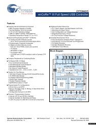
<strong>Delcom</strong> <strong>Products</strong> <strong>Inc</strong>.4 Circuit Layout<strong>USB</strong><strong>IO</strong><strong>HID</strong> <strong>Datasheet</strong>Revision 4 – 4/7/20094.1 Typical SchematicBelow is a typical schematic of the <strong>USB</strong> chip and required external parts. At a minimum youwill need to install at least the R1 and C1. C2, C3 and L1 (ferrite bead) are optional. C2 andC3 are recommended. <strong>Inc</strong>lude C2 when the total current draw is over 25mA. <strong>Inc</strong>lude C3 forESD rejection and increase reliability. <strong>Inc</strong>lude L1 to reduce EMI. Note an external crystal orresonator is not required. The 6Mhz clock is now incorporated internally in the chip.Furthermore pin P2.1 can be used as an extra input.4.2 Backward CompatibilityThe <strong>USB</strong> <strong>HID</strong> chips are backwards compatible with the older type circuit layout used ingeneration I chips. The generation I chips used a 7.5K pull up on D- to +5V, this configurationcan still be used. But the recommended circuit above improves reliability. Also the crystal orresonator used in generation I chips is not longer used.<strong>USB</strong><strong>IO</strong><strong>HID</strong>.pdf Copyright © DELCOM PRODUCTS INC. 2009. All Rights Reserved. Page 5 of 34<strong>Delcom</strong> <strong>Products</strong> <strong>Inc</strong>. 200 William St STE302 – Port Chester NY 10573 USA (914)934-5170 www.delcomproducts.com
<strong>Delcom</strong> <strong>Products</strong> <strong>Inc</strong>.<strong>USB</strong><strong>IO</strong><strong>HID</strong> <strong>Datasheet</strong>Revision 4 – 4/7/20095 Programmed Features5.1 Basic I/OThe <strong>USB</strong> <strong>HID</strong> I/O chips provide general 8 bit input/output commands as well as individual setand reset commands of each pin. See write command 1,2,10,11, 12 and read commands100.5.2 Write data with StrobeSee write commands 13, 14, 15 and 16.The write strobe feature allows the <strong>USB</strong> I/O chip to interface to another device by using astandard 8-bit data bus with a strobe pin. The data is placed on port 0 and the strobe isselectable on one of the port 1 pins. Theses functions allow one to eight data bytes to be senton either a positive and negative strobe (pulse). The write strobe functions support anoptional acknowledge signal.Commands 13 and 14 produces the following sequence; 1) Data in is written to Port 0. 2) Thestrobe pin is toggled active for 1.5us. Optionally, if the acknowledge pin is enabled the strobepin will wait while the acknowledge pin is held low (See command 10-40 bit 3). 3) Then thestrobe pin is toggled non-active. 4) And finally 0xFF is written to Port 0. The strobe pin andthe data on port 0 must be initially preset to there no active states before using this function.Port0 should be preset to 0xFF.Commands 15 and 16 produces the following sequence; 1) Data in Data Extension is writtento Port 0 LSB first. 2) The strobe pin is set active for 1.5us. If the acknowledge pin is enabledthe strobe pin will wait while the acknowledge pin is held low (See command 10-40 bit 3). 3)Then the strobe pin is made non-active. 4) And finally 0xFF is written to Port 0. 4) Systemthen delays for the specified time set in Data LSB byte. 5) Then the process is repeated till alldata bytes in the Data Extension have been sent. The delay is equal to8.25us+(0.75us*DelayValue) Example: Command 8,18,10,15,10,1,4,0,0,0,0 will send 4 bytesof data (all zeros here) on a high strobe on pin one of port one with a delay of 15.75us. Thestrobe pin and the data on port 0 must be initially preset to there no active states before usingthis function.5.3 Read Data with StrobeSee read commands 1 and 2.The read strobe feature allows the <strong>USB</strong> I/O chip to interface to another device by using astandard 8-bit data bus with a strobe pin. The data is captured on port 0 with a active strobeon port1. The strobe pin can be either active high or low. Note before using this command,users should preset Port1 to 0xFF to place Port1 in input mode. The read data strobecommand will produce the following sequence. 1) The selected strobe pin on Port 1 is madeactive. 2) Delay for 1.5us. 3) Data us latched on Port0 and stored. 4) The strobe pin isreleased.5.4 Clock GeneratorThese functions generate a clock source with variable frequency and duty cycle. Up to fourseparate clocks can be configured. The clock outputs can be selected on port 1 pins 0<strong>USB</strong><strong>IO</strong><strong>HID</strong>.pdf Copyright © DELCOM PRODUCTS INC. 2009. All Rights Reserved. Page 6 of 34<strong>Delcom</strong> <strong>Products</strong> <strong>Inc</strong>. 200 William St STE302 – Port Chester NY 10573 USA (914)934-5170 www.delcomproducts.com
<strong>Delcom</strong> <strong>Products</strong> <strong>Inc</strong>.<strong>USB</strong><strong>IO</strong><strong>HID</strong> <strong>Datasheet</strong>Revision 4 – 4/7/2009through 3. Clock pins can be preset to a predefined state. Use command 20 to enable thisfeature.See write commands 19, 20, 21, 22, 23, 24, 25, 26, 27, 28 and 29.Frequency and duty commands (21-24). The LSB data value sets the period when the portpin is high and the MSB data value sets the period when the port pin is low. The defaultresolution of the period is 10ms, but this can be changes with the prescalar command (19).The resolution of the duty cycle is 0.39 percent.5.5 PWMThis feature allows for a PWM function on ports1 pins P1.0 though P1.3. Use write command34 to configure the PWM feature. To enabled the PWM feature on a pin you must write alow(zero) to that pin. A PWM value of 100(100%) will keep the pin low infinitely. Any valueless than 100 will produce a PWM on the selected port pin. To disable the PWM function youmust set the duty to 100 (100%). When the duty is set to 100 (100%) the pin function is it’snormal state (high or low depend on how it is set). See write command 34.5.6 Port SetupThese features allow the user to place the I/O in one of 4 modes. Each pin on ports 0 and 1can be set independently. The boot up default is mode C. To change the port pin modes usewrite commands 45-48.GP<strong>IO</strong> Mode tableModeMode 1 ValueCommand 46,48Mode 0 ValueCommand 45,47Port type whendata out is lowPort type whendata out is highA 0 0 Hi-Z / CMOS Hi-Z / TTLB 0 1 Medium (8mA)Sink / CMOSC – DefaultBoot up State1 0 Low (2mA)Sink / CMOSHigh (30mA)Drive / CMOSPull up (14K) /CMOSD 1 1 High (50mA)Sink / CMOSHigh (30mA)Drive / CMOSMaximum cumulative source drive current for all GP<strong>IO</strong> is 30mA.Maximum cumulative sink drive current for all GP<strong>IO</strong> is 70mA.See http://www.delcomproducts.com/downloads/cy7c637xx-B.pdf for more GP<strong>IO</strong> details.5.7 Read BufferThis feature allows the <strong>USB</strong> I/O chip to interface to a device using a standard 8-bit data busand a read strobe pin. Data is read on port 0 with a read strobe (pulse) on one of theselectable port 1 pins. The data read buffer is 7 bytes deep. If the read data buffer is full,new data will not be accepted and the over flow flag will be set. Note this function cannot beused while the RS232 functions are in uses. See read command 5.<strong>USB</strong><strong>IO</strong><strong>HID</strong>.pdf Copyright © DELCOM PRODUCTS INC. 2009. All Rights Reserved. Page 7 of 34<strong>Delcom</strong> <strong>Products</strong> <strong>Inc</strong>. 200 William St STE302 – Port Chester NY 10573 USA (914)934-5170 www.delcomproducts.com
<strong>Delcom</strong> <strong>Products</strong> <strong>Inc</strong>.5.8 Scratch Pad<strong>USB</strong><strong>IO</strong><strong>HID</strong> <strong>Datasheet</strong>Revision 4 – 4/7/2009The scratch pad allows the user to write 8 bytes of user defined information in to the <strong>USB</strong> I/Odevice. This area can be used for storing user variables, states or other information. Notethis function cannot be used while the RS232 functions or Read Buffer functions are in uses.5.9 Event CounterThe event counter feature allows the counting of events on one or more of the port 0 pins.The resolution of the counter is 4 bytes. Counting is done on either a rising or falling edge.Active edge is set up with write command 43 and enabled with write command 38. The actualcounted value is returned with read command 8.5.10 RS232 Serial PortThe RS232 functions allow the chip to interface to a RS232 compliant device. Currently thebaud rate is fixed at 2400bit/sec with 8 data bit, one stop bit and no parity. To use the RS232function first enable it with commands 10-40, then use command 10-50 to send data and 11-50 to receive data. You can check the internal buffer count with command 11-9. The RS232pins are fixed with transmit at port 0 pin 7, receive at port 0 pin 6 and clear to send at port 0pin 5. This command supports a maximum transfer of 7 bytes per command.5.11 I 2 C PortThe I2C functions allow the chip to interface to an I2C compliant device. The I2C portsupports the standard clock rate of 100 KHz. The SCLK signal is on port 0 pin 0 and the SDAsignal is on port 0 pin 1. There are two write commands; 60-Write and 63-Selective ReadSetup. There are three read commands; 60-Read, 61-Selective 8bit Address Read, and 62-Selective 16bit Address Read. This command supports a maximum transfer of eight bytesper command. If any error occur during the I2C communications bit 4 of byte 7 is set (seeread command 9).In firmware version 23 and above we added the ability to change the output drive mode of theI2C pins. The default power up mode is CMOS. This can be changed to open drain using the110 write command, bit 0. The open drain mode is useful when connected to 3.3volt I2Cdevices.Generic I2C Write. – Writes up to 8bytes of data.Usage: Write Cmd 60: LSBData=Add/Cmd(B0), MSBData=Length(bytes to send),ExtData[0..7]=Data to write.I2C output:[START] [Add/Cmd(B0)] [Write ExtData0..7] [STOP]Generic I2C Read. - Reads up to 8bytes of data. This action requires two commands, firstsetup the command with write command 63, then call the read 60 command.Usage: Write Cmd 63: LSBData=0, MSBData=Length(bytes to read),HidData(0)=Add/Cmd(B0), HidData(1)=0, HidData(2)=0, HidData(3)=0Usage: Read Cmd 61: Read the data.I2C output:[START] [Add/Cmd(B0)] [Read Data0..7] [STOP]<strong>USB</strong><strong>IO</strong><strong>HID</strong>.pdf Copyright © DELCOM PRODUCTS INC. 2009. All Rights Reserved. Page 8 of 34<strong>Delcom</strong> <strong>Products</strong> <strong>Inc</strong>. 200 William St STE302 – Port Chester NY 10573 USA (914)934-5170 www.delcomproducts.com
<strong>Delcom</strong> <strong>Products</strong> <strong>Inc</strong>.<strong>USB</strong><strong>IO</strong><strong>HID</strong> <strong>Datasheet</strong>Revision 4 – 4/7/2009Generic I2C 8 Bit Address Selective Read. - Reads up to 8bytes of data at a specific 8bitaddress or register. This action requires two commands, first setup the command with writecommand 63, then call the read 61 command.Usage: Write Cmd 63: LSBData=0, MSBData=Length(bytes to read),HidData(0)=Add/Cmd(B0), HidData(1)=AddressLSB(B1), HidData(2)=0,HidData(3)=RdSelCmd(B2)Usage: Read Cmd 61: Read the data.I2C output:[START] [Add/Cmd(B0)] [AddressLSB(B1)] [START] [RdSelCmd(B2)] [Read Data0..7][STOP]Generic I2C 16 Bit Address Selective Read. - Reads up to 8bytes of data at a specific 16bitaddress or register. This action requires two commands, first setup the command with writecommand 63, then call the read 62 command.Usage: Write Cmd 63: LSBData=0, MSBData=Length(bytes to read),HidData(0)=Add/Cmd(B0), HidData(1)=AddressLSB(B1), HidData(2)= AddressLSB(B2),HidData(3)=RdSelCmd(B3)Usage: Read Cmd 62: Read the data.I2C output:[START] [Add/Cmd(B0)] [AddressLSB(B1)] [AddressMSB(B2)] [START] [RdSelCmd(B3)][Read Data0..7] [STOP]5.12 64 Bit Read/Write commandThe 64 bit read/write commands allows the user to read or write 64 bits (8 Bytes) of data withone command to eight 8-bit hardware latches. Theses commands require extra hardware.See the <strong>USB</strong>64B<strong>IO</strong>-Sch.pdf schematic on our website. The command writes a 3bit addresson port1 then writes or reads a byte value on Port 0 with a wr/rd strobe on Port 1.5.13 SPI PortThe SPI functions allow the chip to interface to an SPI compliant device. The I2C portsupports a variable clock period from 20ns to 5.1ms. The default clock is 200ns and can bechanged with write command 91. The SCLK signal is on port 0 pin 7, the MOSI signal is onport 0 pin 6 and the MISO signal is on port 0 pin 5. This command supports a maximumtransfer of eight bytes per command. There are two SPI commands they are 90-Write SPIData and 90-Read SPI Data.The write 90 SPI command will send up to 64 bit of data over the SPI bus. At the same timethis command is writing the data out on the MOSI pin, the input values on MISO is capturedand can be later read with read command 90.In firmware version 23 and above we added the ability to change the output drive mode of theSPI pins. The default power up mode is CMOS. This can be changed to open drain using the110 write command, bit 1. The open drain mode is useful when connected to 3.3volt I2Cdevices.<strong>USB</strong><strong>IO</strong><strong>HID</strong>.pdf Copyright © DELCOM PRODUCTS INC. 2009. All Rights Reserved. Page 9 of 34<strong>Delcom</strong> <strong>Products</strong> <strong>Inc</strong>. 200 William St STE302 – Port Chester NY 10573 USA (914)934-5170 www.delcomproducts.com
<strong>Delcom</strong> <strong>Products</strong> <strong>Inc</strong>.<strong>USB</strong><strong>IO</strong><strong>HID</strong> <strong>Datasheet</strong>Revision 4 – 4/7/20095.14 Buzzer CommandThis feature is intended to be used to drive a buzzer or other auditory device. The feature isfixed on port 1 pin 3 (also H-Bridge Option below). The command number for this feature is70. The frequency, duty cycle and repeat value are all programmable. The frequency isprogrammed by setting the buzzer’s frequency time variable, the units are in 256us. Forexample a desired buzzer frequency of 1KHz would yield a frequency value of around 4. Thebuzzer‘s on time and off time variables are used to program the duty cycle of the buzzer.These units are in 50ms. If you want the buzzer to turn on and off every second you wouldprogram 10 for the on time and off time. The repeat value dictates what mode the buzzer willbe in. If a value of zero is used for the repeat value then the buzzer will sound continuously atthe frequency specified until the user turns it off. If a value of 255 is used then the buzzer willsound at the frequency and duty cycle specified until the user turns it off. If any other value isused the buzzer will sound at the frequency and duty cycle specified and repeat for that manytimes. The DataLSB turns this feature on (1) or off (0). The DataMSB sets the frequency. TheDataExt[0] sets the repeat value. The Data Ext[1] sets the on time. And the Data Ext[2] setsthe off time.Freq Value Freq(Hz) Freq Value Freq(Hz) Freq Value Freq(Hz)1 3906 5 781 9 4342 1953 6 651 10 3903 1302 7 558 11 3554 976 8 488 12 325// Buzzer Example (Freq=3906Hz DutyOn=200ms DutyOff=100ms Repeat=3)MajorCmd =102;// note this is a 16byte commandMinorCmd =70;// Buzzer CommandLSBData = 0x01;// Turn buzzer onMSBData = 0x01;// Set the frequencyDataExt0 = 3;// Repeat 3 timesDataExt1 = 4;// On Duty 200msDataExt2 = 2;// Off Duty 100msH-Bridge Option – In version 25 and above the buzzer function can optionally drive an H-Bridge circuit. See H-Bridge function below. When the H-Bridge controller has been set tomode 1 or mode 2, this function will driver the H-Bridge pins (P0.0-P0.3) instead of P1.3. Alsowhile the buzzer function is running P1.1 is automatically brought low and returned high whenthe buzzer function terminates. The P1.1 is intend to be connected to the H-Bridge powerenable circuit.5.15 Auto Clear & Auto ConfirmThe Auto Clear and Auto Confirm feature are intended for the <strong>Delcom</strong> <strong>USB</strong> indicatorlight. They use the built in button of the indicator (on port 0 pin 0) to either on off theled lights (AutoClear) and/or to sound the buzzer in the indictor light when the buttonis pressed (Auto Confirm). In order to use this feature you must first enable the event<strong>USB</strong><strong>IO</strong><strong>HID</strong>.pdf Copyright © DELCOM PRODUCTS INC. 2009. All Rights Reserved. Page 10 of 34<strong>Delcom</strong> <strong>Products</strong> <strong>Inc</strong>. 200 William St STE302 – Port Chester NY 10573 USA (914)934-5170 www.delcomproducts.com
<strong>Delcom</strong> <strong>Products</strong> <strong>Inc</strong>.<strong>USB</strong><strong>IO</strong><strong>HID</strong> <strong>Datasheet</strong>Revision 4 – 4/7/2009counter (see write command 38). The write command number 72 controls thesefeature. DataLSB bit 6 enables or disables the Auto Clear feature. And DataLSB bit 7enables or disables the Auto Confirm feature5.16 Pulse CommandThis command allows the user to send a custom pulse stream on port 0 or port 1. Thecommand number is 76. All 8bits on either port0 or port1 can be changed. The LSBDataparameter contains the delay prescaler and the port select bit. Bit 7 of the LSBData selectsthe port, a low selects port 0 and high selects port 1. The remaining bits 6 through 0 hold theprescaler value. The prescaler range is 0 to 127. The delay between the states is equal to(DelayValue+1) x Prescalar x ~2us. There are 5 port pin state change parameters and 4delay parameters. The change the port data parameters change the port value by executinga XOR with the current port value and the StateXPortXORData value. So to toggle a pin setthe StateXPortXORData bit value high. You can toggle as many pins as you like. Up to 5states can be set, for less than 5 states set the remaining data to all zeros. The initial portvalue should be preset with the write port command. Note this command processes inlineand therefore no other command will be processed till this command terminates.// Pulse Command exampleMajorCmd =102;// note this is a 16byte commandMinorCmd =76;// Pulse CommandLSBData = 0x01;// PortSelect=Port0 and Prescaler=1MSBData = 0x01; // S0PortXORData - Toggle P0.0DataExt0 = 10;// S0Delay – delay for 10 x 1 x 2us = 20usDataExt1 = 0x02; // S1PortXORData - Toggle P0.1DataExt2 = 5;// S1Delay – delay for 10 x 1 x 2us = 20usDataExt3 = 0x02; // S2PortXORData - Toggle P0.1DataExt4 = 5;// S2Delay – delay for 10 x 1 x 2us = 20usDataExt5 = 0x02; // S3PortXORData - Toggle P0.1DataExt6 = 10;// S3Delay – delay for 10 x 1 x 2us = 20usDataExt7 = 0x03; // S4PortXORData - Toggle P0.0 & P0.1States 0 1 2 3 4Port0.0 __--------------------____Port0.1 _______-----_____-----____5.17 H-Bridge FunctionThe H-Bridge control functions is intended to drive an H-Bridge circuit. The H-Bridge functioncan be used to drive DC motor or a buzzer. Pins P0.0 through P0.3 are used to control the H-Bridge. Pin P0.0 drives the bottom right transistor, P0.1 drives the top right transistor, P0.2drives the top left transistor and P0.3 drives the bottom left transistor. The active level is low.The H-bridge mode is set with the write command 71. The LSB Data parameter is used to setthe mode. There are 4 modes; 0=off (All pins high), 1=State 1 (forward), 2=State 2(reverse),0xFF=Brake (both bottom drivers low). Default boot up pins values are all high.<strong>USB</strong><strong>IO</strong><strong>HID</strong>.pdf Copyright © DELCOM PRODUCTS INC. 2009. All Rights Reserved. Page 11 of 34<strong>Delcom</strong> <strong>Products</strong> <strong>Inc</strong>. 200 William St STE302 – Port Chester NY 10573 USA (914)934-5170 www.delcomproducts.com
<strong>Delcom</strong> <strong>Products</strong> <strong>Inc</strong>.<strong>USB</strong><strong>IO</strong><strong>HID</strong> <strong>Datasheet</strong>Revision 4 – 4/7/20096 Firmware Communications6.1 OverviewThere two ways to communicate with the <strong>USB</strong> <strong>HID</strong> device. They are the direct and indirectmethods. The direct method communicates directly to the <strong>USB</strong> driver via the OS APIfunctions. The indirect method communicates to the <strong>USB</strong> <strong>HID</strong> device via the <strong>Delcom</strong> DLL.Using the <strong>Delcom</strong> DLL is the easiest way of communicating with the <strong>USB</strong> <strong>HID</strong> device and isbackwards compatible with the older generation I <strong>USB</strong> Chips Sets. You can also mix indirectand direct functions. For example you can use the DLL to get the device name and then youthe direct method to open and write/read to the device.6.1.1 Indirect Method – <strong>Delcom</strong> DLLUsing the <strong>Delcom</strong> DLL is the simplest method to communicate with the <strong>USB</strong> device. Simplycopy the DLL in your program executing directory (e.g. bin/debug) or to a searchable systempath (e.g. windows/system32). Then including the prototyping or declaration file in yourproject and start calling the DLL functions. The DLL also offers enhanced functions thatsimplify the communication with the <strong>USB</strong> device. See the <strong>Delcom</strong> DLL for more information.// Simply C# <strong>Delcom</strong> DLL Examplepublic class Main{unsigned int hDevice = 0;int Result;byte Port0, Port1;StringBuilder DeviceName = new tringBuilder("",<strong>Delcom</strong>.MAXDEVICENAMELEN);}cout
<strong>Delcom</strong> <strong>Products</strong> <strong>Inc</strong>.<strong>USB</strong><strong>IO</strong><strong>HID</strong> <strong>Datasheet</strong>Revision 4 – 4/7/2009check the Family ID (FID) and/or the unique serial number (SID) in each <strong>Delcom</strong> <strong>USB</strong> <strong>HID</strong>Chip. The device name can change each time the <strong>USB</strong> device is plugged in, so you mustsearch for the device name each time.<strong>USB</strong> <strong>HID</strong> GUID: {4D1E55B2-F16F-11CF-88CB-001111000030}<strong>Delcom</strong> <strong>USB</strong> VID: 0x0FC5<strong>Delcom</strong> <strong>USB</strong> PID: 0xB080<strong>Delcom</strong> <strong>USB</strong> FID: 1=<strong>IO</strong>Chips, 2=VisualIndicators, 3=NumericDisplays,4=PanelLigths, 5=Buzzers,<strong>Delcom</strong> <strong>USB</strong> SID: Unique Serial NumberOnce the device name has been found, we use it to create or open the device. The openfunction returns a handle to the device. This handle is then used to communicate with thedevice and to finally close the device when we are done with it. In Windows use theCreateFile() functions to open the device. Note some OS required <strong>USB</strong> <strong>HID</strong> device to alwaysbe opened in a shared mode.//In MS Windows we would use the following functions:GetHidGuid()// Returns the unique <strong>USB</strong> <strong>HID</strong> GUIDSetupDiGetClassDevs()// Returns the device detailsSetupDiEnumDeviceInterfaces () // Returns the device interfaceSetupDiGetDeviceInterfaceDetail() // Returns the interface detailsCreateFile()// Opens the deviceHidD_GetAttributes()// Returns the device attributtesHidD_SetFeature// Writes to the deviceHidD_GetFeature// Read from the deviceCloseFile() or CloseHandle() // Closes the deviceWriting and reading to the device is done by passing a small buffer to the write and readsystem API functions. The buffer we call a data packet. This data packet is preset by the userto the command numbers and parameters we want and then sent down to the <strong>USB</strong> device.The <strong>USB</strong> device acts on the data packet and in a read commands returns data in the samedata packet that we passed. All data packets are at least 8 byte long. The transmit(TX) andreceive(RX) data/command packets are defined below.6.2 TX Command Packet Format:Major Command 1 ByteMinor Command 1 ByteData LSB1 ByteData MSB1 ByteData<strong>HID</strong>[0..3] 4 BytesDataExt[0..7]8 Bytes(Optional)6.3 Rx Command Packet Format:ReadData[0..15]8-16 Bytes<strong>USB</strong><strong>IO</strong><strong>HID</strong>.pdf Copyright © DELCOM PRODUCTS INC. 2009. All Rights Reserved. Page 13 of 34<strong>Delcom</strong> <strong>Products</strong> <strong>Inc</strong>. 200 William St STE302 – Port Chester NY 10573 USA (914)934-5170 www.delcomproducts.com
<strong>Delcom</strong> <strong>Products</strong> <strong>Inc</strong>.<strong>USB</strong><strong>IO</strong><strong>HID</strong> <strong>Datasheet</strong>Revision 4 – 4/7/20096.4 Write CommandsThis section describes the <strong>USB</strong><strong>IO</strong><strong>HID</strong> write commands. There are currently twomajor commands (101 and102) for the write command/data functions. A majorcommand of 101 will send an 8 byte write command. A major command of 102 willsend a 16 byte write command. In the future we will add two more commands tosend 32 and 64 byte write commands. Note you can always send a higher numberof bytes of a write command, but not the opposite.MajorCmd = 101 – Send an 8 Byte write command.MajorCmd = 102 – Send an 16 Byte write command.6.4.1 Port Write FunctionsMinorCmd = 0Length = 8 or 16 BytesMinorCmd = 1LSBData = Port0ValueLength = 8 BytesMinorCmd = 2LSBData = Port1Length = 8 BytesMinorCmd = 3LSBData =ReadStrobeMSBData = Port1ValueLength = 8 BytesMinorCmd = 8LSBData = LSBWriteMSBData = MSBWriteLength = 8 BytesMinorCmd = 10LSBData = Port0ValueMSBData = Port1ValueLength = 8 BytesMinorCmd = 11LSBData = Port0ResetMSBData = Port0SetLength = 8 BytesMinorCmd = 12LSBData = Port1ResetMSBData = Port1SetLength = 8 BytesMinorCmd = 13LSBData = Port0DataMSBData = Port1Strobe0 - Test function. Writes the command/data packet to the devicecommand/data buffer. Uses for testing purposes, command doesnothing. The written command/data packet can be read with readcommands 101 or 102.1 – Write Port 0. Writes the LSB data to Port02 – Write Port 1. Writes the LSB data to Port13 – Setup Read Strobe. The LSB data value sets the read strobe pin tobe used in read commands 1 and 2. See read commands 1 and 2.8 – Setup 64bit Write 2Bytes Read 8bytes.. The LSB data value LSBwrite data and the MSB data value sets the MSB write data. See readcommand 1810 – Write both the port 0 and port 1 values. The LSB data is writtento Port0 and the MSB data is written to Port1.11 - Sets or resets the port 0 pins individually. The LSB resets thecorresponding port pin(s) and the MSB sets the corresponding portpin(s) on port 0. Resetting the port pin(s) takes precedence over settingthe bits.12 - Sets or resets the port 1 pins individually. The LSB resets thecorresponding port pin(s) and the MSB sets the corresponding portpin(s) on port 1. Resetting the port pin(s) takes precedence over settingthe bits.13 - Write strobe high function. This command writes the LSB to port0 and then toggles the corresponding pin marked in the MSB byte highthen low.<strong>USB</strong><strong>IO</strong><strong>HID</strong>.pdf Copyright © DELCOM PRODUCTS INC. 2009. All Rights Reserved. Page 14 of 34<strong>Delcom</strong> <strong>Products</strong> <strong>Inc</strong>. 200 William St STE302 – Port Chester NY 10573 USA (914)934-5170 www.delcomproducts.com
<strong>Delcom</strong> <strong>Products</strong> <strong>Inc</strong>.<strong>USB</strong><strong>IO</strong><strong>HID</strong> <strong>Datasheet</strong>Revision 4 – 4/7/2009Length = 8 BytesMinorCmd = 14LSBData = Port0DateMSBData = Port1StrobeLength = 8 BytesMinorCmd = 15LSBData = DelayMSBData = Port1StrobeExtData0..7 = DataBufferLength = 16 BytesMinorCmd = 16LSBData = DelayMSBData = Port1StrobeExtData0..7 = DataBufferLength = 16 BytesMinorCmd = 17ExtData0..7 = DataBufferLength = 16 Bytes14 - Write strobe low function. This command writes the LSB to port0 and then toggles the corresponding pin marked in the MSB byte lowthen high.15 - Write 8-byte strobe high function. This command writes the DataExtension data to port 0 and then toggles the corresponding pin marked in the MSB bytehigh then low and then delays for the specified time set in the LSB byte.16 - Write8-byte strobe low function. This command writes the DataExtension data to port 0 and then toggles the corresponding pin marked in the MSB bytelow then high and then delays for the specified time set in the LSB byte.17 - Write 64 Bit Command. This command writes 8 bytes of data tothe external hardware latches. The data is passed in the data extensionregisters. The LSB of the data extension is written to address zero. Thiscommand requires external hardware. See <strong>USB</strong>64B<strong>IO</strong>-Sch.pdf on ourwebsite.6.4.2 Port Clock FunctionsMinorCmd = 19LSBData = PrescalarLength = 8 BytesMinorCmd = 20LSBData = DisableMSBData = EnableLength = 8 BytesMinorCmd = 21LSBData = HighDutyMSBData = LowDutyLength = 8 BytesMinorCmd = 22LSBData = HighDutyMSBData = LowDutyLength = 8 BytesMinorCmd = 22LSBData = HighDutyMSBData = LowDutyLength = 8 BytesMinorCmd = 23LSBData = HighDutyMSBData = LowDutyLength = 8 BytesMinorCmd = 2519 - Loads the Clock Generator Global Prescalar value. This valueis passed in the LSB register. <strong>Inc</strong>reasing this number decreases all theclock function frequencies. Prescalar range is 1 to 255 and the boot updefault value is 10.20 - Enables or disables the clock generator on port 1. The lowernibble of the LSB disables the corresponding port pin(s) and the lowernibble of the MSB enables the corresponding port pin(s). Disabling theport pin(s) takes precedence over enabling.21 - Loads the frequency and duty cycle for port 1 pin 0. The LSBdata sets the high duty cycle and the MSB data sets the low duty cycleon port 1 pin 0.22 - Loads the frequency and duty cycle for port 1 pin 1. The LSBdata sets the high duty cycle and the MSB data sets the low duty cycleon port 1 pin 1.22 - Loads the frequency and duty cycle for port 1 pin 2. The LSBdata sets the high duty cycle and the MSB data sets the low duty cycleon port 1 pin 2.23 - Loads the frequency and duty cycle for port 1 pin 3. The LSBdata sets the high duty cycle and the MSB data sets the low duty cycleon port 1 pin 3.25 - Synchronizes the clock generation. This command synchronizes<strong>USB</strong><strong>IO</strong><strong>HID</strong>.pdf Copyright © DELCOM PRODUCTS INC. 2009. All Rights Reserved. Page 15 of 34<strong>Delcom</strong> <strong>Products</strong> <strong>Inc</strong>. 200 William St STE302 – Port Chester NY 10573 USA (914)934-5170 www.delcomproducts.com
<strong>Delcom</strong> <strong>Products</strong> <strong>Inc</strong>.LSBData = EnableMSBData = PresetLength = 8 BytesMinorCmd = 26LSBData = DelayValueLength = 8 BytesMinorCmd = 27LSBData = DelayValueLength = 8 BytesMinorCmd = 28LSBData = DelayValueLength = 8 BytesMinorCmd = 29LSBData = DelayValueLength = 8 Bytes<strong>USB</strong><strong>IO</strong><strong>HID</strong> <strong>Datasheet</strong>Revision 4 – 4/7/2009all the clock generators to start now plus an initial phase delay, seebelow. The lower nibble of the LSB enables this function on thecorresponding pins P1.0 to P1.3. The lower nibble of the MSB presetsthe initial value on the corresponding pins P1.0 to P1.3. Initial phasedelay resolution is in 10ms and is passed in the LSB register. Initialphase delay registers are cleared after this command is sent. Thereforethe initial phase delay registers must be set each time this command iscalled.26 - Load initial phase delay on port 1 pin 0. Sets the LSB data asthe port1 pin0 initial delay value. To be used with command 25.27 - Load initial phase delay on port 1 pin 1. Sets the LSB data asthe port1 pin0 initial delay value. To be used with command 25.28 - Load initial phase delay on port 1 pin 2. Sets the LSB data asthe port1 pin0 initial delay value. To be used with command 25.29 - Load initial phase delay on port 1 pin 3. Sets the LSB data asthe port1 pin0 initial delay value. To be used with command 25.6.4.3 Port Setup FunctionsMinorCmd = 30Length = 8 BytesMinorCmd = 31Length = 8 BytesMinorCmd = 33Length = 8 BytesMinorCmd = 33Length = 8 BytesMinorCmd = 34LSBData = Port1PinValueMSBData = PWMValueLength = 8 Bytes30 - Enable or disable port 0 pull up resistors. This command is notsupported; it has been left for backwards compatibility. See new portsetup commands 44-48.31 - Enable or disable port 1 pull up resistors. This command is notsupported; it has been left for backwards compatibility. See new portsetup commands 44-48.32 - Setup port 0 pins sink current level. This command is notsupported; it has been left for backwards compatibility. See new portsetup commands 44-48.33- Setup port 1 pins sink current level. This command is notsupported; it has been left for backwards compatibility. See new portsetup commands 44-48.34 - Load the PWM values. Port pins P1.0 through P1.3 can beplaced is PWM mode by writing the PWM value with this command. TheLSB Data parameter is the port pin number, range is 0-3. The MSBData parameter is the PWM value, range is 0-100.<strong>USB</strong><strong>IO</strong><strong>HID</strong>.pdf Copyright © DELCOM PRODUCTS INC. 2009. All Rights Reserved. Page 16 of 34<strong>Delcom</strong> <strong>Products</strong> <strong>Inc</strong>. 200 William St STE302 – Port Chester NY 10573 USA (914)934-5170 www.delcomproducts.com
<strong>Delcom</strong> <strong>Products</strong> <strong>Inc</strong>.<strong>USB</strong><strong>IO</strong><strong>HID</strong> <strong>Datasheet</strong>Revision 4 – 4/7/20096.4.4 Feature commandsMinorCmd = 35LSBData = Storbe PinLength = 8 BytesMinorCmd = 37LSBData = DataMSBData = Address[0-7]Length = 8 BytesMinorCmd = 38LSBData = EnablePinMSBData = DisablePinLength = 8 BytesMinorCmd = 40LSBData = CtrlReg ValueLength = 8 Bytes35 - Setup read buffer function. This command sets up the micro toread the current values on port 0 when a read strobe in presented onthe configured strobe pin on port 1. The LSB will enable the correspondpin on port 1 to latch data on port 0 on the active edge. The active edgeis set up the pull ups command 30 and 31. If the pull-ups are enabledthen the active transition is from high to low. Otherwise the activetransition is from low to high. The read buffer is only 7 bytes deep.Default is 0x00, read buffer disabled. See read buffer command 5.Note this function cannot be used while the RS232 functions are inuses.37 - Write scratch pad area. Writes the LSB to the scratch pad. TheMSB contains the pointer to the scratch pad. Pointer values can rangefrom 0 to 7. The scratch pad area is 8 bytes deep. This area can beused for storing user variables, states or information. Defaulted to all0x00 on boot up. Note this function cannot be used while the RS232functions are in uses.38 - Enable/Disable Events Counter. This command sets up the eventcounter. LSB data byte enables this function on the corresponding pinon port 0. The MSB data byte disabled this function on thecorresponding pin on port 0. Once enabled the system will count eventson the enabled pin on the active edge. The active edge is configured bythe pull ups command 10-30 and 10-31. If the pull-ups are enabledthen the active transition is from high to low. Otherwise the activetransition is from low to high. The event counter value is read withcommand 11-8. This feature is off by default.40 - Enable/Disable Control Register. This function sets the controlregister value. Each bit in this register controls different options. TheLSB data byte sets the control register.Bit 0: Status LED. When set Port1 pin 3 (P1.3) will toggle low when <strong>USB</strong> communicationsare present. Only available on this pin.Bit 1: Enables the RS232 Serial port with fixed 2400 baud rate. Version 5.Bit 3: Enables the acknowledge pin in the write strobe functions 13,14,15 &16. Theacknowledge pin is only available on pin P1.2 and is active low. The write strobe will beextended while the acknowledge pin is held low. Version 8.Bits7-4,2: Future Implementation. These bits are reserved for future implementation andshould be set to zero for future compatibility.<strong>USB</strong><strong>IO</strong><strong>HID</strong>.pdf Copyright © DELCOM PRODUCTS INC. 2009. All Rights Reserved. Page 17 of 34<strong>Delcom</strong> <strong>Products</strong> <strong>Inc</strong>. 200 William St STE302 – Port Chester NY 10573 USA (914)934-5170 www.delcomproducts.com
<strong>Delcom</strong> <strong>Products</strong> <strong>Inc</strong>.<strong>USB</strong><strong>IO</strong><strong>HID</strong> <strong>Datasheet</strong>Revision 4 – 4/7/20096.4.5 Interrupt and Port ModeMinorCmd = 43LSBData = Port0IntEdgeLength = 8 BytesMinorCmd = 44LSBData = Port1IntEdgeLength = 8 BytesMinorCmd = 45LSBData = Port0ModeLength = 8 BytesMinorCmd = 46LSBData = Port0Mode1Length = 8 BytesMinorCmd = 47LSBData = Port1Mode0Length = 8 BytesMinorCmd = 48LSBData = Port1Mode1Length = 8 Bytes43 - Set Port 0 Interrupt Edge.The LSB Data parameter sets the Port 0 Interrupt Edge. 1= Risingedge, 0=Falling edge.44 - Set Port 1 Interrupt Edge.The LSB Data parameter sets the Port 1 Interrupt Edge. 1= Risingedge, 0=Falling edge.45 - Configures Port 0 GP<strong>IO</strong> – Mode 0 RegisterThe LSB data parameter is the value passed. Each bit represents a portpin. See the GP<strong>IO</strong> Mode table.46 - Configures Port 0 GP<strong>IO</strong> – Mode 1 RegisterThe LSB data parameter is the value passed. Each bit represents a portpin. See the GP<strong>IO</strong> Mode table.47 - Configures Port 1 GP<strong>IO</strong> – Mode 0 RegisterThe LSB data parameter is the value passed. Each bit represents a portpin. See the GP<strong>IO</strong> Mode table.48 - Configures Port 1 GP<strong>IO</strong> – Mode 1 RegisterThe LSB data parameter is the value passed. Each bit represents a portpin. See the GP<strong>IO</strong> Mode table.<strong>USB</strong><strong>IO</strong><strong>HID</strong>.pdf Copyright © DELCOM PRODUCTS INC. 2009. All Rights Reserved. Page 18 of 34<strong>Delcom</strong> <strong>Products</strong> <strong>Inc</strong>. 200 William St STE302 – Port Chester NY 10573 USA (914)934-5170 www.delcomproducts.com
<strong>Delcom</strong> <strong>Products</strong> <strong>Inc</strong>.<strong>USB</strong><strong>IO</strong><strong>HID</strong> <strong>Datasheet</strong>Revision 4 – 4/7/20096.4.6 Communication CommandsMinorCmd = 50ExtData[0] = LengthExtData[1..7] = DataLength = 16 BytesMinorCmd = 60LSBData = Add/Cmd(B0)MSBData = LengthExtData[0..7] = DataLength = 16 BytesMinorCmd = 61LSBData = Add/Cmd(B0)MSBData = Address(B1)Length = 8 BytesMinorCmd = 62LSBData = RdSelCmd(B2)MSBData = LengthLength = 8 BytesMinorCmd = 63LSBData = 0MSBData = LengthHidData0 = Add/Cmd(B0)HidData1 = AddLSB(B1)HidData2 = AddMSB(B2)HidData3 =RdSelCmd(B2/3)Length = 8 BytesMinorCmd = 70LSBData = On/OffMSBData = LengthDataExt[0] = Repeat ValueDataExt[1] = OnTimeDataExt[2] = Off TimeLength = 16 BytesMinorCmd = 71LSBData = ModeLength = 8 Bytes50 - Writes to the RS232 Serial Port. This command sends data to theserial port. Both the data count and data are passed in the DataExtension. The MSB and LSB bytes should be zero. The data count isin the LSB byte (first byte of the DataExt) and the data is in theremaining 7 bytes. Issuing this command clears the TX Status register(see 11-9). Example command 8,18,0,0,6,5,1,2,3,4,5 will send 5 bytesof data (1,2,3,4,5) to the serial port.60 - Write to the I2C Port. This command writes the data found in thedata extension to the I2C device. The device address/command is setin the Data LSB byte and the number of bytes to send is set in the DataMSB byte. If an error occurs bit 4/7 of byte 7 is set in the systemparameters bytes, else reset. See read command 9.61 -I2C Selective Read Setup 1. Note this is an old command left forbackwards compatibility with generation I chip sets. It is recommendedthat you use command 63 instead of this command.This commands setups the selective read command 61. You will alsoneed to call command number 62 to setup the selective read. The DataLSB should be set to the device address/command (byte 0) and theData MSB should be set to the selective read address (byte 1). Alsosee read command 61.62 -I2C Selective Read Setup 2. Note this is an old command left forbackwards compatibility with generation I chip sets. It is recommendedthat you use command 63 instead of this command.This commands setups the selective read command 61. You will alsoneed to call command number 61 to setup the selective read. The DataLSB should be set to the device read command (byte 2) and the DataMSB should be set to the read length. Also see read command 61.63 -I2C Selective Read Setup. This commands setups the selectiveread command 61. The Data LSB is not used and should be set to zerofor future compatibility. The Data MSB is set to the read length in bytes.The HidData0 is set to the I2C device address/command (byte 0). TheHidData1 is set to the LSB address of the I2C device. The HidData2 isset to the MSB address of the I2C device (byte 2), this byte is only sentin 16 bit mode. The HidData3 is set to the I2C read command this willbe byte 2 or 3 depending on the mode used. Once this command hasbeen sent the user should call the read 61 or 62 command.70 – Buzzer Control. This command is used to drive a buzzer on port 0pin3. See the buzzer control description for more information.71 – H-Bridge Control. This command is used to control the H-Bridgefunctions. The LSBData parameter configures the H-Bridge mode.Values: 0=Off, 1=State 1 (forward), 2=State 2(reverse),0xFF= Brake(both lower drivers are on). See H-Bridge description for more info.<strong>Inc</strong>luded in firmware version 25 and above.<strong>USB</strong><strong>IO</strong><strong>HID</strong>.pdf Copyright © DELCOM PRODUCTS INC. 2009. All Rights Reserved. Page 19 of 34<strong>Delcom</strong> <strong>Products</strong> <strong>Inc</strong>. 200 William St STE302 – Port Chester NY 10573 USA (914)934-5170 www.delcomproducts.com
<strong>Delcom</strong> <strong>Products</strong> <strong>Inc</strong>.<strong>USB</strong><strong>IO</strong><strong>HID</strong> <strong>Datasheet</strong>Revision 4 – 4/7/2009MinorCmd = 72LSBData = ControlByteLength = 8 BytesMinorCmd = 76LSBData = Port & PrescalarMSBData = S0PortXORDataDataExt0= S0DelayDataExt1 = S1PortXORDataDataExt2= S1DelayDataExt1 = S2PortXORDataDataExt4= S2DelayDataExt1 = S3PortXORDataDataExt6= S3DelayDataExt7 = S4ortXORDataLength = 16 Bytes72 – Auto Clear & Auto Confirm Control. This command enables ordisables the Auto Clear and Auto Confirm feature. Bit 6 of the DataLSBcontrols the Auto Clear feature and bit 7 controls the Auto Confirmfeature. A high value enables the feature and low disables it.76 – Pulse Control. This command allows the user to send a custompulse stream on port 0 or port 1. See the Pulse Command describtionfor more information.MinorCmd = 90LSBData = Bit LengthExtData[0..7] = DataLength = 16 BytesMinorCmd = 110LSBData = Disbale BitsLSBData = Enable BitsLength = 8 Bytes90 - Write to the SPI port. This commands writes up to 8 bytes (64bits)of data (passed in the DataExt) to the SPI port. The number of bit towrite is passed in the LSB Byte, range is 1-64. Also see command 11-90 to read the MISO data.110 – Enable/Disable Option0 Bits.. This command enables ordisables the option0 bits. There are 8 options bits. Set thecorresponding bit in LSBData high to disable the option. And set thecorresponding bit in MSBData high to enable the option. The option0default value is zero.Bit 0 – I2C Output Mode. 0=CMOS, 1=Open drain.Bit 1 – SPI Output Mode. 0=CMOS, 1=Open drain.Bit 3-7 Reversed for future use.<strong>Inc</strong>luded in firmware version 23 and above.<strong>USB</strong><strong>IO</strong><strong>HID</strong>.pdf Copyright © DELCOM PRODUCTS INC. 2009. All Rights Reserved. Page 20 of 34<strong>Delcom</strong> <strong>Products</strong> <strong>Inc</strong>. 200 William St STE302 – Port Chester NY 10573 USA (914)934-5170 www.delcomproducts.com
<strong>Delcom</strong> <strong>Products</strong> <strong>Inc</strong>.<strong>USB</strong><strong>IO</strong><strong>HID</strong> <strong>Datasheet</strong>Revision 4 – 4/7/20096.5 Read CommandsThis section describes the <strong>USB</strong><strong>IO</strong><strong>HID</strong> read commands. To send a read command senda user defined buffer to the <strong>USB</strong> <strong>HID</strong> read function. The first byte passed in the buffermust be preset to the command number. On a successfully return of the <strong>USB</strong> <strong>HID</strong> readfunction, the buffer passed will return the requested read data. Read command canreturn 8 to 16 bytes of requested data, see individual commands for command readlength.Command = 0Command = 1Length = 8 BytesCommand = 2Length = 8 BytesCommand = 5Length = 8 BytesCommand = 7Length = 8 BytesCommand = 8Length = 8 BytesCommand = 9Length = 8 or 16 Bytes0 – Not supported. See read command 100 for read ports command..1- Reads port 0 with High strobe. Reads the current data on port 0 with a highstrobe on pin X on port 1. The LSB sets up which pin is to be used for the high strobe.See Read port 0 with strobe sequence below.2 - Reads port 0 with Low strobe. Reads the current data on port 0 with a lowstrobe on pin X on port 1. The LSB sets up which pin is to be used for the low strobe.See Read port 0 with strobe sequence below.5 - Reads the Read Buffer. This command is setup with the read Buffer SetupCommand 35. The LSB byte returned is the read buffer status byte, it will contain thenumber of bytes available in the read buffer. The next 7 bytes contain the data. The readdata buffer is only 7 bytes deep. Data is filled from byte 1 to byte 7. If the read data bufferis full and another read strobe occurs before this command is read. Then the read bufferstatus byte will be set to 0xFF and the new data byte would be lost. The user must checkthe read status byte to see if; new data is present, not present or present with data overflow. This command resets the read status byte to zero. Note this function cannot be usedwhen the RS232 function is in use.7 - Reads the 8 bytes in the scratch pad area. Default values are zero.8 - Reads the event counter value. This command returns the 4 byte eventcounter value and then resets the counter. If the counter over flows then the over flowstatus byte will be set to 0xFF otherwise it will be 0x0. The event counter is returned inthe first 4 bytes and the over flow byte is in the 5 byte.9 - Reads system variables. This function returns the following system variables.This command can be read as an 8 or 16 byte command.Byte0: Control Register.Byte1: Clock Generator Pre-Scalar.Byte2: Port 0 Pull Up Register.Byte3: Port 1 Pull Up Register.Byte4: <strong>USB</strong> Port Address.Byte5: RS232 Rx Status. Returns the available data count in the lower nibble.Bit 7of 7 is set on Rx Buffer overflow and bit 6/7 is set on Rx framing error.Byte6: RS232 Tx Status. The lower nibble returns the number of data bytes still pendingin the Tx buffer.Bit 7of 7 is set on a Tx buffer overflow.Byte7: Bit 4/7 is set if an I2C error is detected. This bit is update each time an I2C functionis called.Byte8: Option0 – See write command 110 for more information.Byte9-15: Reversed for future use.<strong>USB</strong><strong>IO</strong><strong>HID</strong>.pdf Copyright © DELCOM PRODUCTS INC. 2009. All Rights Reserved. Page 21 of 34<strong>Delcom</strong> <strong>Products</strong> <strong>Inc</strong>. 200 William St STE302 – Port Chester NY 10573 USA (914)934-5170 www.delcomproducts.com
<strong>Delcom</strong> <strong>Products</strong> <strong>Inc</strong>.<strong>USB</strong><strong>IO</strong><strong>HID</strong> <strong>Datasheet</strong>Revision 4 – 4/7/2009Command = 10Length = 8 BytesCommand = 12Length = 8 BytesCommand = 17Length = 8 BytesCommand = 18Length = 8 BytesCommand = 50Length = 8 BytesCommand = 60Length = 8 BytesCommand = 61Length = 8 Bytes10 - Reads the firmware information.Byte 0-3: Unique Device Serial Number. DWORD Little Endian.Byte 4: Firmware Version.Byte 5: Firmware Date.Byte 6: Firmware Month.Byte 7: Firmware Year.12 - Reads 8 bytes of memory data.This is peek functions used only for firmware debugging. Address was be preset withwrite command 3.17 - Read 64 Bit Command. This command reads 8 bytes of data from theexternal hardware. The LSB of the returned data is address zero. This command requiresexternal hardware. See <strong>USB</strong>64B<strong>IO</strong>-Sch.pdf on our website.18 - Write 2 bytes, Read 8 byte Command. This command reads 8 bytes ofdata from the external hardware, similar to the above command. But the data setup inwrite command 8, is write to address 0 and 1. See write setup command 8. Thiscommands requires external hardware. See <strong>USB</strong>64B<strong>IO</strong>-Sch.pdf on our website.50 - Reads the RS232 Rx Buffer.This byte returns 8 bytes, the first byte is the Rx Buffer Status and data count and theremaining bytes are the RS232 data bytes. The Rx buffer is 7 bytes deep and is in LSBfirst order. The Rx Status and data count byte are cleared when this command is issued.The lower nibble of the status byte contains the Rx buffer data length count, pin 7of 7 ofthe rx status byte is set on an Rx overflow and pin 6 of 7 is set on a Rx framing error.Note you can read both the Rx Status and Tx Status bytes with command 11-9 withoutclearing there content.60 -Reads from the I2C Port.Reads 1 to 8 bytes of data from the I2C port. This command must be pre setup with writecommands 63. If an error occurs bit 4/7 of byte 7 in read command 9 is set, else reset.Also see read command 9.61 - Selective Reads from the I2C Port (8-Bit Address)This command is typically used in I2C memory devices. This command first writes a 8bitselective address and then reads 1 to 8 bytes of data from the I2C port. This commandmust be pre setup with write command 63 (or commands 61 and 62). If an error occursbit 4/7 of byte 7 in read command 9 is set, else reset. Also see read command 9.Command = 62Length = 8 Bytes62 - Selective Reads from the I2C Port (16-Bit address)This command is typically used in I2C memory devices. This command first writes 16bitselective address and then reads 1 to 8 bytes of data from the I2C port. This commandmust be pre setup with write command 63. If an error occurs bit 4/7 of byte 7 in readcommand 9 is set, else reset. Also see read command 9.Command = 90Length = 8 BytesCommand = 100Length = 8 BytesCommand = 101Length = 8 Bytes90 - Read SPI Data.Returns 8 bytes (64bits) of data captured from the last SPI write command (90). To readdata from the SPI port first send Write SPI data command 90 and then send thiscommand.100 - Read ports 0 and port 1. This command will read the currently port values.The first byte (LSB) will contain the current value on port 0 and the second byte (MSB) willcontain the current value on port 1. The third byte returns the clock enable status on port1. And the fourth byte returns the Port2 values.101 – Read 8 Byte Command Buffer. This command returns the values of thelast 8 byte value in the command buffer. This command does not alter the commandbuffer. The command can be used to double check that your last write or read commandwas sent or received correctly. This command can be used for testing or for missioncritical designs.<strong>USB</strong><strong>IO</strong><strong>HID</strong>.pdf Copyright © DELCOM PRODUCTS INC. 2009. All Rights Reserved. Page 22 of 34<strong>Delcom</strong> <strong>Products</strong> <strong>Inc</strong>. 200 William St STE302 – Port Chester NY 10573 USA (914)934-5170 www.delcomproducts.com
<strong>Delcom</strong> <strong>Products</strong> <strong>Inc</strong>.<strong>USB</strong><strong>IO</strong><strong>HID</strong> <strong>Datasheet</strong>Revision 4 – 4/7/2009Command = 102Length = 16 Bytes102 – Read 16 Byte Command Buffer. This command returns the values ofthe last 16 byte value in the command buffer. This command does not alter the commandbuffer. The command can be used to double check that your last write or read commandwas sent or received correctly. This command can be used for testing or for missioncritical designs.Command = 103Length = 8 Bytes103 – Read Errors. . This command will read the currently error value. After thiscommand has been sent the current error value is reset to zero. Return values:Bytes0-1: FamilyCode (1=<strong>USB</strong> Chips, 2=Visual Indicators, 3=Numeric Display, 4=TLights)Bytes2: Firmware versionByte3: Always zeroByte4: System ErrorBit0 – Set on power up.Bit1 – Watch Dog ResetBit2 – Low Voltage ResetBit3 – Invalid ISR ResetBit4 – <strong>USB</strong> No Data ErrorByte5: Command ErrorBit0 – Write Command failed or not supported.Bit1 – Read Command failed or not supported.Byte6: Generic ErrorCommand = 104Length = 16 Bytes104 – Read Family. This command will return the current family number. The returnsyntax is as follows.Bytes0-1: FamilyCode (1=<strong>USB</strong> Chips, 2=Visual Indicators, 3=Numeric Display, 4=TLights,5=Buzzer)Bytes2-3: Security CodeByte4: Firmware versionByte5: Firmware DateByte6: Firmware MonthByte7: Firmware YearBytes8-10: Serial Number<strong>USB</strong><strong>IO</strong><strong>HID</strong>.pdf Copyright © DELCOM PRODUCTS INC. 2009. All Rights Reserved. Page 23 of 34<strong>Delcom</strong> <strong>Products</strong> <strong>Inc</strong>. 200 William St STE302 – Port Chester NY 10573 USA (914)934-5170 www.delcomproducts.com
<strong>Delcom</strong> <strong>Products</strong> <strong>Inc</strong>.<strong>USB</strong><strong>IO</strong><strong>HID</strong> <strong>Datasheet</strong>Revision 4 – 4/7/20097 SpecificationsFor more specifications all so see the Cypress data sheet CY7C637XX.7.1 Absolute Maximum RatingsStorage Temperature -65C to +150COperating Temperature -0C to +70CVss relative to Vcc-0.5V to +7.0VDC Input Voltage-0.5V to Vcc+0.5VDC voltage on HiZ pins-0.5V to Vcc+0.5VMax Current Summed on Port1 pins 60maMax Current Summed on Port0 pins 10maPower Dissipation300mWStatic Discharge Voltage >2000VLatch Up Current200mA7.2 Electrical CharacteristicsVCC Operating Current20mAVCC Limits 4 to 5.25VMax GP<strong>IO</strong> Sink Current70mA*Max GP<strong>IO</strong> Source Current30mA*Pull Up Resistor24Kohms* Cumulative across all ports.7.3 CommunicationsPacket Bandwidth*100 Packet/sec* The <strong>USB</strong> 1.1 Low Speed specification defines the maximum packet period to be10ms. Therefore you can send a read or write command every 10ms or 100 packetsper second. Depending on the command you can send 8 or 16 byte per packet.<strong>USB</strong><strong>IO</strong><strong>HID</strong>.pdf Copyright © DELCOM PRODUCTS INC. 2009. All Rights Reserved. Page 24 of 34<strong>Delcom</strong> <strong>Products</strong> <strong>Inc</strong>. 200 William St STE302 – Port Chester NY 10573 USA (914)934-5170 www.delcomproducts.com
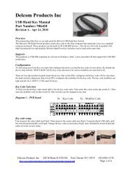
<strong>Delcom</strong> <strong>Products</strong> <strong>Inc</strong>.8 Package Diagrams<strong>USB</strong><strong>IO</strong><strong>HID</strong> <strong>Datasheet</strong>Revision 4 – 4/7/2009<strong>USB</strong><strong>IO</strong><strong>HID</strong>.pdf Copyright © DELCOM PRODUCTS INC. 2009. All Rights Reserved. Page 25 of 34<strong>Delcom</strong> <strong>Products</strong> <strong>Inc</strong>. 200 William St STE302 – Port Chester NY 10573 USA (914)934-5170 www.delcomproducts.com
<strong>Delcom</strong> <strong>Products</strong> <strong>Inc</strong>.<strong>USB</strong><strong>IO</strong><strong>HID</strong> <strong>Datasheet</strong>Revision 4 – 4/7/20099 Ordering InformationOrder Number Number of GP<strong>IO</strong> Package Type902270 10 18 Pin (300Mil) SOIC902370 10 18 Pin (0.300”) DIP902670 16 24 Pin (300Mil) SOIC902770 16 24 Pin (0.300”) DIP10 Firmware Release NotesVersion 20 - Nov 1 2008 - Initial ReleaseVersion 21 - Dec 2 2008 – Added support for <strong>Delcom</strong> Indicator products.Version 22 - Jan 9 2009 – Fixed auto clear, auto confirm and I2C 16bit read command.- Added more error bits to the error command. Fixed event counter.Version 23 - Jan 16 2009 – Added open drain options for I2C and SPI. See write cmd 110.Version 24 - Jan 27 2009 – Fixed error in 64Bit read command 17.Version 25 - Mar 26 2009 – Added H-Bridge command. See write cmd 71.<strong>USB</strong><strong>IO</strong><strong>HID</strong>.pdf Copyright © DELCOM PRODUCTS INC. 2009. All Rights Reserved. Page 26 of 34<strong>Delcom</strong> <strong>Products</strong> <strong>Inc</strong>. 200 William St STE302 – Port Chester NY 10573 USA (914)934-5170 www.delcomproducts.com
<strong>Delcom</strong> <strong>Products</strong> <strong>Inc</strong>.<strong>USB</strong><strong>IO</strong><strong>HID</strong> <strong>Datasheet</strong>Revision 4 – 4/7/200911 Trouble ShootingIf Windows does not see the <strong>USB</strong> device in the Windows Device Manager or it is listed as an'Unknown device' then you have a hardware problem. Most common errors are; ReservedD+/D- (green/white) wires, incorrect pull up resistor on the D- pin (1.3K resistor to the VREGpin), missing +5volts or ground, and VPP pin not tied to ground. Make sure your circuitmatches the circuit in the Typical Schematic section above.12 Notes12.1 Power NotesWhen the device boots up the total current consumed by the device should be at a minimumto comply with the <strong>USB</strong> standard (less than 25mA).Cable length and cable size should be selected in order to maintain an operating voltage atthe <strong>USB</strong> I/O chip of at least 4 volts. Failure to maintain 4 volts at the <strong>USB</strong> chip will cause it toreset.This device can be used in a self-powered mode or with an external power supply if morethan 450mA is required by the user’s circuit. When using external power supplies, connectthe <strong>USB</strong> I/O chip VCC to the <strong>USB</strong> supplied power and run the user added circuitry off theexternal power supply. Do not connect the <strong>USB</strong> VCC and external power supplies together,only connect the grounds.12.2 InterfacingWhen interfacing the <strong>USB</strong> I/O chip to your circuit, one must be careful not to over load thecurrent on the individually pins or the total maximum current for the chip. Also one most notexceed the voltage maximums on the pins. If the voltage or current exceeds the limits of thechip you will have to add buffering to your design. For example most relays require more than25mA to actuate the relay, and the <strong>USB</strong> I/O device can only sink 25mA. Therefore a currentamplifier is required, such as a transistor or opto-coupler. When working with excessivecurrents, voltages or with high EMI circuits it is recommended that you use relays and/oropto-couplers to isolate the circuits.<strong>USB</strong><strong>IO</strong><strong>HID</strong>.pdf Copyright © DELCOM PRODUCTS INC. 2009. All Rights Reserved. Page 27 of 34<strong>Delcom</strong> <strong>Products</strong> <strong>Inc</strong>. 200 William St STE302 – Port Chester NY 10573 USA (914)934-5170 www.delcomproducts.com
<strong>Delcom</strong> <strong>Products</strong> <strong>Inc</strong>.<strong>USB</strong><strong>IO</strong><strong>HID</strong> <strong>Datasheet</strong>Revision 4 – 4/7/200913 Examples13.1 C++ Example Direct ExampleThe following code snippet is not complete, shown here for example purposes only. For thecomplete code listing see the link in the references section. The following C function scansfor the <strong>USB</strong> <strong>HID</strong> device and optionally tests for the family type number and serial number. Ifthe device is found it copies the device handle to the global variable hDevice, saves thedevice name, and leaves the file open.Note that the device can be opened in a shared or non-shared mode. Most OS required <strong>HID</strong>device to be opened in a shared mode.#define <strong>USB</strong>_VID 0x0FC5 // <strong>USB</strong> Vendor ID (Always 0x0FC5 for <strong>Delcom</strong> products)#define <strong>USB</strong>_PID 0xB080 // <strong>USB</strong> Product ID (Always 0xB080 for <strong>Delcom</strong> <strong>HID</strong> device)#define <strong>USB</strong>_TID 0x0001 // <strong>USB</strong> Type ID (0=all, 1=<strong>USB</strong><strong>HID</strong><strong>IO</strong>, 2=<strong>USB</strong><strong>HID</strong>VI,…)#define <strong>USB</strong>_SID 0x0000 // <strong>USB</strong> Serial ID (zero=scan for all)HANDLE hDevice;// Handle to the devicechar DeviceName[512]; // Devicename string// ------------------------------------------------------ //// ScanForHidDevice(VID,PID,TID,SID) - Scan thru all the <strong>HID</strong> device lookking// for a match on the VID, PID and optional TID (Type ID) and SID(SerialNum)// Sets the hDevice ghandle varible if found and opens the device// Return zero if found, else non-zero error code.// 0 = Success// 1 = No matching <strong>HID</strong> devices// ------------------------------------------------------ //unsigned int ScanFor<strong>HID</strong>Device(unsigned int VID, unsigned int PID, unsigned intTID, unsigned int SID ){//Use a series of API calls to find a <strong>HID</strong> with a matching Vendor,Product,Type and Serial ID.<strong>Delcom</strong>DeviceInfoStruct <strong>Delcom</strong>Info;PSP_DEVICE_INTERFACE_DETAIL_DATA detailData;GUIDHidGuid;HANDLEhDevInfo;ULONGRequired;<strong>HID</strong>D_ATTRIBUTESAttributes;SP_DEVICE_INTERFACE_DATAdevInfoData;boolLastDevice = FALSE;int MemberIndex = 0;boolMyDeviceDetected = FALSE;LONGResult;ULONGLength;// Variable initLength = 0;detailData = NULL;hDevice=NULL;MemberIndex = 0;LastDevice = FALSE;HidD_GetHidGuid(&HidGuid);// Get the GUID for all system <strong>HID</strong>s.hDevInfo=SetupDiGetClassDevs(&HidGuid, NULL, NULL, DIGCF_PRESENT |DIGCF_INTERFACEDEVICE);devInfoData.cbSize = sizeof(devInfoData);do {MyDeviceDetected=FALSE;Result=SetupDiEnumDeviceInterfaces(hDevInfo, 0, &HidGuid, MemberIndex,&devInfoData);if (Result != 0)<strong>USB</strong><strong>IO</strong><strong>HID</strong>.pdf Copyright © DELCOM PRODUCTS INC. 2009. All Rights Reserved. Page 28 of 34<strong>Delcom</strong> <strong>Products</strong> <strong>Inc</strong>. 200 William St STE302 – Port Chester NY 10573 USA (914)934-5170 www.delcomproducts.com
<strong>Delcom</strong> <strong>Products</strong> <strong>Inc</strong>.<strong>USB</strong><strong>IO</strong><strong>HID</strong> <strong>Datasheet</strong>Revision 4 – 4/7/2009{ //A device has been detected, so get more infoResult = SetupDiGetDeviceInterfaceDetail(hDevInfo, &devInfoData, NULL, 0,&Length, NULL); // zero length call to get sizedetailData = (PSP_DEVICE_INTERFACE_DETAIL_DATA)malloc(Length);detailData -> cbSize = sizeof(SP_DEVICE_INTERFACE_DETAIL_DATA);Result = SetupDiGetDeviceInterfaceDetail(hDevInfo, &devInfoData, detailData,Length, &Required, NULL);// To open device in a non-share mode, change the 3 parameter to NULLhDevice=CreateFile(detailData->DevicePath, GENERIC_READ|GENERIC_WRITE,FILE_SHARE_READ|FILE_SHARE_WRITE,(LPSECURITY_ATTRIBUTES)NULL, OPEN_EXISTING, 0,NULL);Attributes.Size = sizeof(Attributes);Result = HidD_GetAttributes(hDevice, &Attributes);MyDeviceDetected = FALSE;if( (Attributes.VendorID == VID) && (Attributes.ProductID == PID)){MyDeviceDetected = TRUE;strncpy(DeviceName, detailData->DevicePath, 512); // save the devicename/* optional check for Family id and serial number, See Appendix Aif(TID || SID) { // Now check for TID and SID if non-zeroif(GetDeviceInfo(&<strong>Delcom</strong>Info)) MyDeviceDetected = FALSE;else {if(TID && (<strong>Delcom</strong>Info.Family != TID)) MyDeviceDetected = FALSE;if(SID && (<strong>Delcom</strong>Info.Serial != SID)) MyDeviceDetected = FALSE;}} // end of TID or SID*/}Else {//The PID and/or VID doesn't match. Close the device try the next oneCloseHandle(hDevice);hDevice = 0;}free(detailData);} //if (Result != 0)else { // End of List - No <strong>HID</strong> devices detected!LastDevice=TRUE; // returned 0, so there are no more devices to check.}//If we haven't found the device yet, then try the next one.MemberIndex++;} // loop till either end of deivce list or we find our devicewhile ((LastDevice == FALSE) && (MyDeviceDetected == FALSE));SetupDiDestroyDeviceInfoList(hDevInfo);if (MyDeviceDetected == FALSE) {// Device not foundhDevice = 0;return(1);}else {// Device FoundHidD_SetNumInputBuffers(hDevice,1);return(0); // Success}}//Free the memory<strong>USB</strong><strong>IO</strong><strong>HID</strong>.pdf Copyright © DELCOM PRODUCTS INC. 2009. All Rights Reserved. Page 29 of 34<strong>Delcom</strong> <strong>Products</strong> <strong>Inc</strong>. 200 William St STE302 – Port Chester NY 10573 USA (914)934-5170 www.delcomproducts.com
<strong>Delcom</strong> <strong>Products</strong> <strong>Inc</strong>.Write example.<strong>USB</strong><strong>IO</strong><strong>HID</strong> <strong>Datasheet</strong>Revision 4 – 4/7/2009// GEN2 Example to set port0 & port1 to 0xFF.typedef union <strong>HID</strong>PacketStruct {unsigned char Data[256];struct {unsigned char MajorCmd;unsigned char MinorCmd;unsigned char DataLSB;unsigned char DataMSB;unsigned char Data<strong>HID</strong>[4];unsigned char DataExt[8];} Tx;struct {unsigned char Cmd;} Rx;} <strong>HID</strong>PacketStruct, *p<strong>HID</strong>PacketStruct;<strong>HID</strong>Packetstruct MyPacket; // Declare the packetMyPacket.Tx.MajorCmd = 101; // Fill the packetMyPacket.Tx.MinorCmd = 1;MyPacket.Tx.DataLSB = 0xFF;HidD_SetFeature(hDevice,MyPacket, 8) // lastly send the packetRead example.// GEN2 <strong>USB</strong> Write/Read Command/Data Packettypedef union <strong>HID</strong>PacketStruct {unsigned char Data[256];struct {unsigned char MajorCmd;unsigned char MinorCmd;unsigned char DataLSB;unsigned char DataMSB;unsigned char Data<strong>HID</strong>[4];unsigned char DataExt[8];} Tx;struct {unsigned char Cmd;} Rx;} <strong>HID</strong>PacketStruct, *p<strong>HID</strong>PacketStruct;<strong>HID</strong>Packetstruct MyPacket; // Declare the packetMyPacket.Rx.Cmd = 100;// Fill the packet – read ports cmdHidD_GetFeature(hDevice,MyPacket, 8) // lastly send the packetunsigned char Port0 = MyPacket Data[0];unsigned char Port2 = MyPacket Data[1];<strong>USB</strong><strong>IO</strong><strong>HID</strong>.pdf Copyright © DELCOM PRODUCTS INC. 2009. All Rights Reserved. Page 30 of 34<strong>Delcom</strong> <strong>Products</strong> <strong>Inc</strong>. 200 William St STE302 – Port Chester NY 10573 USA (914)934-5170 www.delcomproducts.com
<strong>Delcom</strong> <strong>Products</strong> <strong>Inc</strong>.<strong>USB</strong><strong>IO</strong><strong>HID</strong> <strong>Datasheet</strong>Revision 4 – 4/7/200914 References14.1 Documentation<strong>Delcom</strong> <strong>USB</strong> <strong>HID</strong> Documentation and Exampleshttp://www.delcomproducts.com/productdetails.asp?productnum=900000<strong>Delcom</strong> DLLhttp://www.delcomproducts.com/productdetails.asp?productnum=890510<strong>Delcom</strong> <strong>USB</strong> <strong>HID</strong> Chipshttp://www.delcomproducts.com/products_<strong>USB</strong><strong>IO</strong>.asp<strong>Delcom</strong> Distribution Diskhttp://www.delcomproducts.com/delcomcd/Start.htmCypress CY7C637XX Data Sheet.http://www.delcomproducts.com/downloads/cy7c637xx-B.pdf14.2 Examples<strong>Delcom</strong> <strong>USB</strong> <strong>HID</strong> C# Net Direct Examplehttp://www.delcom-eng.com/productdetails.asp?ProductNum=890630<strong>Delcom</strong> <strong>USB</strong> <strong>HID</strong> C++ Direct Examplehttp://www.delcom-eng.com/productdetails.asp?ProductNum=890607<strong>USB</strong><strong>IO</strong><strong>HID</strong>.pdf Copyright © DELCOM PRODUCTS INC. 2009. All Rights Reserved. Page 31 of 34<strong>Delcom</strong> <strong>Products</strong> <strong>Inc</strong>. 200 William St STE302 – Port Chester NY 10573 USA (914)934-5170 www.delcomproducts.com
<strong>Delcom</strong> <strong>Products</strong> <strong>Inc</strong>.<strong>USB</strong><strong>IO</strong><strong>HID</strong> <strong>Datasheet</strong>Revision 4 – 4/7/2009Optional TID and SID TestIf you plan on also testing for the family type and/or serial number add the following code to yourproject, and uncomment the ‘optional check for Family id and serial number’ code in theScanFor<strong>HID</strong>Device function.// Family Type Valuesenum FamilyType{ALL,<strong>USB</strong><strong>IO</strong>,<strong>USB</strong>VI,<strong>USB</strong>ND};// all <strong>Delcom</strong> <strong>USB</strong> device// all <strong>Delcom</strong> <strong>USB</strong> <strong>IO</strong> Chips & foot switch// all <strong>Delcom</strong> <strong>USB</strong> Visual Indicators// all <strong>Delcom</strong> <strong>USB</strong> Numeric Displays// DataStruct used by the GetDeviceInfo functionstypedef struct <strong>Delcom</strong>DeviceInfoStruct_ {unsigned short int Family;unsigned short int Security;unsigned char Version;unsigned char Day;unsigned char Month;unsigned char Year;unsigned int Serial;unsigned int Spare;} <strong>Delcom</strong>DeviceInfoStruct, *p<strong>Delcom</strong>DeviceInfoStruct;// ---------------------------------------------------------------- //// Reads device info// Returns zero on success, else non-zero// Return data in a 16byte data buffer. Buffer must be predeclared// ---------------------------------------------------------------- //int GetDeviceInfo(p<strong>Delcom</strong>DeviceInfoStruct pInfo){myPacket.Rx.Cmd = 104;if(!HidD_GetFeature(hDevice,&myPacket, 16)) {return(1);}// command failed}// now get the data if the variable has been passedif(!pInfo) return(1);memcpy(pInfo,&myPacket,16);return 0;<strong>USB</strong><strong>IO</strong><strong>HID</strong>.pdf Copyright © DELCOM PRODUCTS INC. 2009. All Rights Reserved. Page 32 of 34<strong>Delcom</strong> <strong>Products</strong> <strong>Inc</strong>. 200 William St STE302 – Port Chester NY 10573 USA (914)934-5170 www.delcomproducts.com
<strong>Delcom</strong> <strong>Products</strong> <strong>Inc</strong>.<strong>USB</strong><strong>IO</strong><strong>HID</strong> <strong>Datasheet</strong>Revision 4 – 4/7/2009Appendix A. Revision HistoryRev Date Author Description0 12/15/2008 DL Initial Release1 01/08/2009 DL Corrected minimum schematic. Addedpulse, auto clear, auto confirm andbuzzer commands. Removedunsupported SPI commands. Fixed misctypos. Added bit details to read errorcommand.2 01/16/2009 DL Added option command #110.3 04/01/2009 DL Added H-Bridge command #71. Addedshared access note.4 04/07/2009 DL Correct Buzzer Example in 5.14.<strong>USB</strong><strong>IO</strong><strong>HID</strong>.pdf Copyright © DELCOM PRODUCTS INC. 2009. All Rights Reserved. Page 33 of 34<strong>Delcom</strong> <strong>Products</strong> <strong>Inc</strong>. 200 William St STE302 – Port Chester NY 10573 USA (914)934-5170 www.delcomproducts.com
<strong>Delcom</strong> <strong>Products</strong> <strong>Inc</strong>.Appendix B. Notices<strong>USB</strong><strong>IO</strong><strong>HID</strong> <strong>Datasheet</strong>Revision 4 – 4/7/2009DELCOM PRODUCTS INC. takes no position regarding the validity or scope of any intellectualproperty or other rights that might be claimed to pertain to the implementation or use of thetechnology described in this document or the extent to which any license under such rights mightor might not be available; neither does it represent that it has made any effort to identify any suchrights. Information on DELCOM PRODUCTS INC procedures with respect to rights in DELCOMPRODUCTS INC. specifications can be found at the DELCOM PRODUCTS INC. website. Copiesof claims of rights made available for publication and any assurances of licenses to be madeavailable, or the result of an attempt made to obtain a general license or permission for the use ofsuch proprietary rights by implementers’ or users of this specification, can be obtained from theDELCOM PRODUCTS INC. Executive Director.DELCOM PRODUCTS INC. invites any interested party to bring to its attention any copyrights,patents or patent applications, or other proprietary rights which may cover technology that may berequired to implement this specification. Please address the information to the DELCOMPRODUCTS INC. Executive Director.Copyright © DELCOM PRODUCTS INC. Open 2009. All Rights Reserved.This document and translations of it may be copied and furnished to others, and derivative worksthat comment on or otherwise explain it or assist in its implementation may be prepared, copied,published and distributed, in whole or in part, without restriction of any kind, provided that theabove copyright notice and this paragraph are included on all such copies and derivative works.However, this document itself may not be modified in any way, such as by removing the copyrightnotice or references to DELCOM PRODUCTS INC., except as needed for the purpose ofdeveloping DELCOM PRODUCTS INC. specifications, in which case the procedures forcopyrights defined in the DELCOM PRODUCTS INC. Intellectual Property Rights document mustbe followed, or as required to translate it into languages other than English.The limited permissions granted above are perpetual and will not be revoked by DELCOMPRODUCTS INC. or its successors or assigns.This document and the information contained herein is provided on an “AS IS” basis andDELCOM PRODUCTS INC. DISCLAIMS ALL WARRANTIES, EXPRESS OR IMPLIED,INCLUDING BUT NOT LIMITED TO ANY WARRANTY THAT THE USE OF THE INFORMAT<strong>IO</strong>NHEREIN WILL NOT INFRINGE ANY RIGHTS OR ANY IMPLIED WARRANTIES OFMERCHANTABILITY OR FITNESS FOR A PARTICULAR PURPOSE.LIFE SUPPORT POLICY - <strong>Delcom</strong> <strong>Products</strong> are not authorized for use in life support devicesand/or systems without the express written approval of <strong>Delcom</strong>.<strong>USB</strong><strong>IO</strong><strong>HID</strong>.pdf Copyright © DELCOM PRODUCTS INC. 2009. All Rights Reserved. Page 34 of 34<strong>Delcom</strong> <strong>Products</strong> <strong>Inc</strong>. 200 William St STE302 – Port Chester NY 10573 USA (914)934-5170 www.delcomproducts.com