AMLOK Rod Clamp Series RCN - Minuteman Controls
AMLOK Rod Clamp Series RCN - Minuteman Controls
AMLOK Rod Clamp Series RCN - Minuteman Controls

Create successful ePaper yourself
Turn your PDF publications into a flip-book with our unique Google optimized e-Paper software.
Page 2
General:<br />
Function:<br />
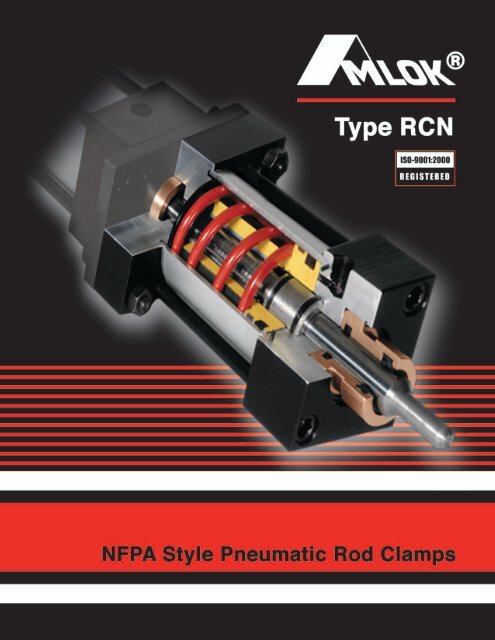
This new 3rd generation NFPA - Style<br />
<strong>AMLOK</strong> ® Pneumatic <strong>Series</strong> <strong>RCN</strong> <strong>Rod</strong> <strong>Clamp</strong><br />
has been developed as a solution to control<br />
problems inherent to pneumatics—over<br />
travel, drifting, bouncing and reverse<br />
traveling. The <strong>AMLOK</strong> ® is one of the world's<br />
only Power-Off <strong>Rod</strong> <strong>Clamp</strong>s available as a<br />
stand-alone unit—able to be mounted to the<br />
NFPA cylinder of your choice, or to be used<br />
with no cylinder at all.<br />
The <strong>AMLOK</strong> ® has been designed with<br />
oversized components to withstand the most<br />
severe applications. For example, the contact<br />
area of the clamping collet is considerably<br />
greater than on similar units. The<br />
increased contact area reduces the pressure-per-square-inch<br />
on the rod,thereby<br />
extending service life.<br />
The patented <strong>AMLOK</strong> ® Type <strong>RCN</strong> consists of<br />
a hard anodized aluminum housing with a<br />
special piston and wedge locking mechanism<br />
actuated by a spring that mechanically locks<br />
the rod. This mechanically-operated intensifying<br />
mechanism increases the force created<br />
by the spring several times to guarantee<br />
quick and secure locking. The clamp is<br />
unlocked when air actuates the piston, which<br />
compresses the spring and releases the<br />
locking device.<br />
Since the locking of the <strong>AMLOK</strong> ® is<br />
accomplished mechanically by a spring and<br />
unlocked by air pressure, loss of air pressure<br />
will cause the unit to lock.<br />
The patented intensifier is a mechanical<br />
design, guaranteeing a long service life, even<br />
under severe operating conditions. Since the<br />
clamping is accomplished through spring<br />
force, drifting caused by a lack of air<br />
pressure is not possible.<br />
The <strong>AMLOK</strong> ® <strong>Rod</strong> <strong>Clamp</strong> is also offered as<br />
an integral unit to an Advanced Cylinder.<br />
Please refer to our Integrated Cylinder<br />
catalog when an integral unit is required.<br />
For hydraulic applications, please refer to our<br />
Type RCH <strong>AMLOK</strong> ® catalog.<br />
Warranty: <strong>AMLOK</strong> ® <strong>RCN</strong> units are<br />
warranted for a period of one (1) year from<br />
date of shipment, to be free from defects of<br />
materials and workmanship, provided said<br />
items are properly applied.<br />
The holding force depends upon the rod and<br />
piston diameter. The available holding forces<br />
can be multiplied by adding additional<br />
<strong>AMLOK</strong> ® clamps to the same rod.<br />
<strong>AMLOK</strong>S ® are designed for locking<br />
reciprocating motions only. To lock rotary<br />
motions, contact the factory.<br />
If these units are to be used as safety<br />
or braking devices, or for additional<br />
information on other models such as the<br />
Sitema Safety Catchers and Power On <strong>Rod</strong><br />
<strong>Clamp</strong>s please consult the factory.<br />
Design Hints:<br />
When attached to cylinders, longer<br />
cylinder rods must be specified to allow for<br />
the length of the <strong>AMLOK</strong> ® . See “L”<br />
dimension in the chart.<br />
If a hollow rod must be clamped, contact<br />
Advanced Machine for guidelines.<br />
Recommended rod tolerances are cited on<br />
page 5. For maximum life, the rod should be<br />
semi-hardened or surface-hardened with<br />
surface finish of about 32 micro inches.<br />
Avoid nicks and burrs which could damage<br />
the wiper and bearings.<br />
The contact surfaces and bores to which the<br />
<strong>AMLOK</strong> ® is clamped must be square and<br />
concentric to each other within .002" T.I.R. to<br />
avoid binding of the rod or excess wear. The<br />
rod must fully engage the clamping device to<br />
avoid distortion of the mechanism.<br />
MISSION STATEMENT<br />
We strive to supply products and services of the highest<br />
value while sharing responsibilities in a rewarding work<br />
environment.<br />
NOTE: <strong>AMLOK</strong> ® <strong>Rod</strong> <strong>Clamp</strong>s can be an<br />
integral part of your housing. We can provide<br />
mating components for your special<br />
applications. When side loads are acting on<br />
the cylinder rod, make sure that the rod is<br />
guided sufficiently in bearings to avoid<br />
excessive side loads on the locking<br />
mechanism. This is especially important at<br />
higher cylinder rod speeds to avoid<br />
overheating the clamping device due to<br />
excessive friction with the rod.<br />
Proper lubrication is important for higher<br />
speeds or continuous side loads.<br />
For special mountings or higher holding<br />
forces, please consult the factory.<br />
VISION STATEMENT<br />
We passionately pursue to be an innovative and exciting<br />
company, valued by our people, customers and suppliers,<br />
and acknowledged by the business community as a world<br />
class leader through the products and services provided.<br />
Page 3
Patented <strong>AMLOK</strong> ® <strong>Rod</strong> <strong>Clamp</strong> Type - <strong>RCN</strong><br />
Standard Specifications<br />
<br />
<br />
<br />
<br />
<br />
<br />
NFPA Mounting Styles<br />
Square Head - Tie <strong>Rod</strong> Design<br />
Maximum Operating Pressure - 160 PSI Air<br />
Required Release Pressure - 60 PSI Air<br />
Operating Media - Filtered Compressed Air<br />
Operating Temperature - Standard 10 F to + 180 F<br />
- Optional 10 F to + 250 F<br />
<br />
<br />
<br />
Cycle Rate: maximum five times per second.<br />
Holding Force - Axial holding forces were established after 2,000,000 fatigue test cycles.<br />
Some linear movement may occur after clamp is fully engaged.<br />
Special units to minimize movement available. Please contact factory.<br />
Part Numbering System<br />
<strong>RCN</strong> XXX XXX X XXX X X XX<br />
<strong>AMLOK</strong> <strong>Series</strong><br />
<strong>Rod</strong> Size - X.XX (INCHES)<br />
Equivalent Cylinder<br />
Bore Size - X.XX (INCHES)<br />
Type "C"= Cylinder Mount/<br />
"S"= Stand Alone<br />
Mounting Style (See pages 4-10)<br />
“P” Port Location (1,2,3, or 4)<br />
Seal Material (N=Standard=Nitrile)<br />
(V=Viton) optional<br />
Surface Coatings: (“Blank” =Standard)<br />
(“EN” =Electroless Nickel) optional<br />
(“SS” =Stainless Steel) optional<br />
EXAMPLE: <strong>RCN</strong> 100 250 S MXO 1 N EN<br />
1.00" ROD SIZE<br />
2.50" DIA. BORE<br />
Type = Stand Alone<br />
NFPA (MXO) Mounting Style<br />
“P” Port Location = (1)<br />
Seal Material = Nitrile<br />
Surface Coating = Electroless Nickel<br />
Page 4
Patented <strong>AMLOK</strong> ® <strong>Rod</strong> <strong>Clamp</strong> Type - <strong>RCN</strong><br />
Technical Data Chart<br />
<strong>AMLOK</strong> ®<br />
Type-<strong>RCN</strong> <br />
063150<br />
063200<br />
063250<br />
100200<br />
100250<br />
100325<br />
100400<br />
100500<br />
138325<br />
138400<br />
138500<br />
138600<br />
175600<br />
200500<br />
250600<br />
<strong>Rod</strong><br />
Dia.<br />
0.625<br />
0.625<br />
0.625<br />
1.000<br />
1.000<br />
1.000<br />
1.000<br />
1.000<br />
1.375<br />
1.375<br />
1.375<br />
1.375<br />
1.750<br />
2.000<br />
2.500<br />
Bore<br />
Dia.<br />
1.500<br />
2.000<br />
2.500<br />
2.000<br />
2.500<br />
3.250<br />
4.000<br />
5.000<br />
3.250<br />
4.000<br />
5.000<br />
6.000<br />
6.000<br />
5.000<br />
6.000<br />
L<br />
5.09<br />
5.09<br />
5.09<br />
5.09<br />
5.09<br />
5.83<br />
5.83<br />
5.83<br />
5.83<br />
5.83<br />
5.83<br />
5.83<br />
6.33<br />
6.08<br />
6.58<br />
E<br />
2.00<br />
2.50<br />
3.00<br />
2.50<br />
3.00<br />
3.75<br />
4.50<br />
5.50<br />
3.75<br />
4.50<br />
5.50<br />
6.50<br />
6.50<br />
5.50<br />
6.50<br />
UF<br />
3.375<br />
4.125<br />
4.625<br />
4.125<br />
4.625<br />
5.500<br />
6.250<br />
7.625<br />
5.500<br />
6.250<br />
7.625<br />
8.625<br />
8.625<br />
7.625<br />
8.625<br />
F<br />
3/8<br />
3/8<br />
3/8<br />
3/8<br />
3/8<br />
5/8<br />
5/8<br />
5/8<br />
5/8<br />
5/8<br />
5/8<br />
3/4<br />
3/4<br />
5/8<br />
3/4<br />
FH<br />
1 1/4<br />
1 1/4<br />
1 1/4<br />
1 1/4<br />
1 1/4<br />
1 3/4<br />
1 3/4<br />
1 3/4<br />
1 3/4<br />
1 3/4<br />
1 3/4<br />
1 3/4<br />
2<br />
1 3/4<br />
2<br />
FC<br />
1”<br />
1”<br />
1”<br />
1”<br />
1”<br />
1 1/4”<br />
1 1/4”<br />
1 1/4”<br />
1 1/4”<br />
1 1/4”<br />
1 1/4”<br />
1 1/4”<br />
1 1/2”<br />
1 1/2”<br />
1 3/4”<br />
FB Dia.<br />
0.312<br />
0.375<br />
0.375<br />
0.375<br />
0.375<br />
0.437<br />
0.437<br />
0.562<br />
0.437<br />
0.437<br />
0.562<br />
0.562<br />
0.562<br />
0.562<br />
0.562<br />
TF<br />
2.750<br />
3.375<br />
3.875<br />
3.375<br />
3.875<br />
4.687<br />
5.437<br />
6.625<br />
4.687<br />
5.437<br />
6.625<br />
7.625<br />
7.625<br />
6.625<br />
7.625<br />
Axial Holding<br />
Force Lbs.<br />
200<br />
400<br />
650<br />
300<br />
450<br />
950<br />
1550<br />
2150<br />
950<br />
1550<br />
1950<br />
2650<br />
2450<br />
1750<br />
1950<br />
Weight<br />
Lbs.<br />
3.2<br />
5.3<br />
7.0<br />
5.1<br />
7.2<br />
15.0<br />
21.7<br />
30.2<br />
15.3<br />
21.2<br />
31.4<br />
45.3<br />
48.0<br />
31.7<br />
45.0<br />
<strong>AMLOK</strong> ®<br />
Type-<strong>RCN</strong> <br />
063150<br />
063200<br />
063250<br />
100200<br />
100250<br />
100325<br />
100400<br />
100500<br />
138325<br />
138400<br />
138500<br />
138600<br />
175600<br />
200500<br />
250600<br />
R<br />
1.430<br />
1.840<br />
2.190<br />
1.840<br />
2.190<br />
2.760<br />
3.320<br />
4.100<br />
2.760<br />
3.320<br />
4.100<br />
4.880<br />
4.880<br />
4.100<br />
4.880<br />
DD<br />
Thread<br />
1/4-28<br />
5/16-24<br />
5/16-24<br />
5/16-24<br />
5/16-24<br />
3/8-24<br />
3/8-24<br />
1/2-20<br />
3/8-24<br />
3/8-24<br />
1/2-20<br />
1/2-20<br />
1/2-20<br />
1/2-20<br />
1/2-20<br />
B<br />
1.125<br />
1.125<br />
1.125<br />
1.500<br />
1.500<br />
1.500<br />
1.500<br />
1.500<br />
2.000<br />
2.000<br />
2.000<br />
2.000<br />
2.375<br />
2.625<br />
3.125<br />
C<br />
0.375<br />
0.375<br />
0.375<br />
0.500<br />
0.500<br />
0.500<br />
0.500<br />
0.500<br />
0.625<br />
0.625<br />
0.625<br />
0.625<br />
0.750<br />
0.875<br />
1.000<br />
A<br />
0.50<br />
0.62<br />
0.62<br />
0.62<br />
0.62<br />
0.75<br />
0.75<br />
0.75<br />
0.75<br />
0.75<br />
0.75<br />
0.75<br />
0.75<br />
0.75<br />
0.88<br />
P<br />
1/8<br />
1/8<br />
1/8<br />
1/8<br />
1/8<br />
1/4<br />
1/4<br />
1/4<br />
1/4<br />
1/4<br />
1/4<br />
1/4<br />
1/4<br />
1/4<br />
1/4<br />
V<br />
5/8<br />
5/8<br />
5/8<br />
7/8<br />
7/8<br />
7/8<br />
7/8<br />
7/8<br />
1<br />
1<br />
1<br />
1<br />
1 1/8<br />
1 1/8<br />
1 1/4<br />
Y<br />
.250<br />
.000<br />
.000<br />
.375<br />
.375<br />
.000<br />
.000<br />
.000<br />
.000<br />
.000<br />
.000<br />
.000<br />
.000<br />
.000<br />
.000<br />
Z<br />
.406<br />
.406<br />
.406<br />
.406<br />
.406<br />
.625<br />
.688<br />
.688<br />
.600<br />
.688<br />
.688<br />
.688<br />
.688<br />
.688<br />
.688<br />
Axial Holding<br />
Force Lbs.<br />
200<br />
400<br />
650<br />
300<br />
450<br />
950<br />
1550<br />
2150<br />
950<br />
1550<br />
1950<br />
2650<br />
2450<br />
1750<br />
1950<br />
Weight<br />
Lbs.<br />
3.2<br />
5.3<br />
7.0<br />
5.1<br />
7.2<br />
15.0<br />
21.7<br />
30.2<br />
15.3<br />
21.2<br />
31.4<br />
45.3<br />
48.0<br />
31.7<br />
45.0<br />
Dimensions subject to change without notice.<br />
Other sizes available upon request (including metric sizes). Maximum rod tolerances +.000"/-.003"<br />
Other sizes available for mounting to 8” and 10” bore cylinders. Contact factory.<br />
Basic Mount Type <strong>RCN</strong>-XXX XXX C MXO X X N XX (Shown Below)<br />
(Face Mounting Using Threads of <strong>AMLOK</strong>) with bushing head end only<br />
Page 5
<strong>AMLOK</strong><br />
®<br />
<strong>Rod</strong> <strong>Clamp</strong> <strong>Series</strong> <strong>RCN</strong> - Mounting Dimensions<br />
MOUNTING ARRANGEMENTS<br />
✹ Indicates Style for Mounting to NFPA Style MF1 Cylinder.<br />
<strong>AMLOK</strong> ® Type <strong>RCN</strong> <strong>Rod</strong> <strong>Clamp</strong>s can be mounted directly to machine or fixture housings or NFPA Style MFI air cylinders.<br />
If desired, the <strong>AMLOK</strong> ® can be used as the main mounting component with the NFPA style MFI cylinder attached.<br />
✹<br />
<strong>RCN</strong> - XXX XXX CMF2<br />
Rear Flange Mount<br />
(NFPA Style MF2 for<br />
cylinder mounting.)<br />
<strong>RCN</strong> - XXX XXX SN<br />
Basic Mount (Face mounting<br />
using threads of <strong>AMLOK</strong>)<br />
with bushing at both ends.<br />
✹<br />
<strong>RCN</strong> - XXX XXX CA<br />
For Cylinder Mounting<br />
Front Flange Mount<br />
(NFPA Style MF1) &<br />
Rear Flange Mount<br />
(NFPA Style MF2)<br />
<strong>RCN</strong> - XXX XXX SMF1<br />
Front Flange Mount<br />
(NFPA Style MF1)<br />
with bushing at both ends.<br />
<strong>RCN</strong> - XXX XXX SA<br />
Both Flanges Mount<br />
(NFPA Style MF1 + MF2)<br />
with bushing at both ends.<br />
<strong>RCN</strong> - XXX XXX CMF1<br />
Front Flange Mount<br />
(NFPA Style MF1)<br />
for cylinder mounting.<br />
Page 6
<strong>AMLOK</strong><br />
®<br />
<strong>Rod</strong> <strong>Clamp</strong> <strong>Series</strong> <strong>RCN</strong> - Mounting Dimensions<br />
<strong>RCN</strong> - XXX XXX CMS4<br />
Bottom Tap Mount (NFPA Style MS4).<br />
<strong>RCN</strong> - XXX XXX SMS4<br />
Bottom Tap Mount (NFPA Style MS4) with bushing at both ends.<br />
<strong>AMLOK</strong> ®<br />
Type<br />
<strong>RCN</strong><br />
NT TK TN YT SN XT<br />
063150<br />
1/4-20<br />
1/4<br />
5/8<br />
1.24<br />
3.60<br />
1.49<br />
063200<br />
5/16-18<br />
1/2<br />
7/8<br />
1.24<br />
3.60<br />
1.49<br />
063250<br />
3/8-16<br />
5/8<br />
1 1/4<br />
1.24<br />
3.60<br />
1.49<br />
100200<br />
5/16-18<br />
1/2<br />
7/8<br />
1.49<br />
3.60<br />
1.74<br />
100250<br />
3/8-16<br />
5/8<br />
1 1/4<br />
1.49<br />
3.60<br />
1.74<br />
100325<br />
1/2-13<br />
11/16<br />
1 1/2<br />
1.56<br />
3.85<br />
2.16<br />
100400<br />
1/2-13<br />
3/4<br />
2 1/16<br />
1.56<br />
3.85<br />
2.16<br />
100500<br />
5/8-11<br />
1<br />
2 11/16<br />
1.41<br />
4.23<br />
1.93<br />
138325<br />
1/2-13<br />
3/4<br />
1 1/2<br />
1.72<br />
3.85<br />
2.26<br />
138400<br />
1/2-13<br />
3/4<br />
2 1/16<br />
1.72<br />
3.85<br />
2.24<br />
138500<br />
5/8-11<br />
1<br />
2 11/16<br />
1.54<br />
4.23<br />
2.05<br />
138600<br />
3/4-10<br />
1 1/8<br />
3 1/4<br />
1.54<br />
4.23<br />
2.05<br />
175600<br />
3/4-10<br />
1 1/8<br />
3 1/4<br />
1.91<br />
4.23<br />
2.43<br />
200500<br />
5/8-11<br />
1<br />
2 11/16<br />
1.91<br />
4.23<br />
2.18<br />
250600<br />
3/4-10<br />
1 1/8<br />
3 1/4<br />
2.17<br />
4.73<br />
2.18<br />
Page 7
<strong>AMLOK</strong><br />
®<br />
<strong>Rod</strong> <strong>Clamp</strong> <strong>Series</strong> <strong>RCN</strong> - Mounting Dimensions<br />
<strong>RCN</strong> - XXX XXX CMS1<br />
Angle Mount (NFPA Style MS1).<br />
<strong>RCN</strong> - XXX XXX SMS1<br />
Angle Mount (NFPA Style MS1) with bushing at both ends.<br />
<strong>AMLOK</strong> ®<br />
Type<br />
<strong>RCN</strong><br />
AO AL AH AT NA S<br />
SA<br />
AB<br />
063150<br />
3/8<br />
1<br />
1 3/16<br />
1/8<br />
7.09<br />
1 1/4<br />
7.09<br />
7/16<br />
063200<br />
3/8<br />
1<br />
1 7/16<br />
1/8<br />
7.09<br />
1 3/4<br />
7.09<br />
7/16<br />
063250<br />
3/8<br />
1<br />
1 5/8<br />
1/8<br />
7.09<br />
2 1/4<br />
7.09<br />
7/16<br />
100200<br />
3/8<br />
1<br />
1 7/16<br />
1/8<br />
7.34<br />
1 3/4<br />
7.09<br />
7/16<br />
100250<br />
3/8<br />
1<br />
1 5/8<br />
1/8<br />
7.34<br />
2 1/4<br />
7.09<br />
7/16<br />
100325<br />
1/2<br />
1 1/4<br />
1 15/16<br />
1/8<br />
8.45<br />
2 3/4<br />
8.33<br />
9/16<br />
100400<br />
1/2<br />
1 1/4<br />
2 1/4<br />
1/8<br />
8.45<br />
3 1/2<br />
8.33<br />
9/16<br />
100500<br />
5/8<br />
1 3/8<br />
2 3/4<br />
3/16<br />
8.70<br />
4 1/4<br />
8.58<br />
11/16<br />
138325<br />
1/2<br />
1 1/4<br />
1 15/16<br />
1/8<br />
8.57<br />
2 3/4<br />
8.33<br />
7/16<br />
138400<br />
1/2<br />
1 1/4<br />
2 1/4<br />
1/8<br />
8.57<br />
3 1/2<br />
8.33<br />
9/16<br />
138500<br />
5/8<br />
1 3/8<br />
2 3/4<br />
3/16<br />
8.82<br />
4 1/4<br />
8.58<br />
11/16<br />
138600<br />
5/8<br />
1 3/8<br />
3 1/4<br />
3/16<br />
8.82<br />
5 1/4<br />
8.58<br />
13/16<br />
175600<br />
5/8<br />
1 3/8<br />
3 1/4<br />
3/16<br />
9.45<br />
5 1/4<br />
9.08<br />
13/16<br />
200500<br />
5/8<br />
1 3/8<br />
2 3/4<br />
3/16<br />
9.20<br />
4 1/4<br />
8.83<br />
11/16<br />
250600<br />
5/8<br />
1 3/8<br />
3 1/4<br />
3/16<br />
9.83<br />
5 1/4<br />
9.33<br />
13/16<br />
Page 8
<strong>AMLOK</strong><br />
®<br />
<strong>Rod</strong> <strong>Clamp</strong> <strong>Series</strong> <strong>RCN</strong> - Mounting Dimensions<br />
<strong>RCN</strong> - XXX XXX CMT1<br />
Head Trunnion Mount (NFPA Style MT1).<br />
<strong>RCN</strong> - XXX XXX SMT1<br />
Head Trunnion Mount (NFPA Style MT1) with bushing at both ends.<br />
<strong>AMLOK</strong> ®<br />
Type<br />
<strong>RCN</strong><br />
TD TL UT XG<br />
063150<br />
1<br />
1<br />
4<br />
1 1/4<br />
063200<br />
1<br />
1<br />
4 1/2<br />
1 1/4<br />
063250<br />
1<br />
1<br />
5<br />
1 1/4<br />
100200<br />
1<br />
1<br />
4 1/2<br />
1 1/2<br />
100250<br />
1<br />
1<br />
5<br />
1 1/2<br />
100325<br />
1<br />
1<br />
5 3/4<br />
1 3/4<br />
100400<br />
1<br />
1<br />
6 1/2<br />
1 3/4<br />
100500<br />
1<br />
1<br />
7 1/2<br />
1 3/4<br />
138325<br />
1<br />
1<br />
5 3/4<br />
1 7/8<br />
138400<br />
1<br />
1<br />
6 1/2<br />
1 7/8<br />
138500<br />
1<br />
1<br />
7 1/2<br />
1 7/8<br />
138600<br />
1 3/8<br />
1 3/8<br />
9 1/4<br />
1 7/8<br />
175600<br />
1 3/8<br />
1 3/8<br />
9 1/4<br />
2 1/8<br />
200500<br />
1<br />
1<br />
7 1/2<br />
2<br />
250600<br />
1 3/8<br />
1 3/8<br />
9 1/4<br />
2<br />
Page 9
<strong>AMLOK</strong> ® ROD CLAMP - ASSEMBLY INSTRUCTIONS<br />
FOR NFPA “MF1” CYLINDER MOUNT:<br />
1. Read Assembly Instructions and<br />
Caution Label on unit.<br />
2. Connect a flexible hose to the pressure<br />
port of the <strong>AMLOK</strong> ® , apply air pressure<br />
to release the clamping mechanism and<br />
slide the <strong>AMLOK</strong> ® over the rod to be<br />
clamped.<br />
3. Align the mounting holes and port hole<br />
to the proper location.<br />
4. Release pressure.<br />
6. Pressurize the <strong>AMLOK</strong> ® to the<br />
specified release pressure.<br />
7. Release and pressurize several times.<br />
With the specified pressure the rod<br />
should move freely through<br />
the <strong>AMLOK</strong> ® .<br />
8. If the rod does not move freely, check<br />
the squareness of the housing and<br />
cylinder contact surface and correct<br />
if necessary.<br />
5. Bolt <strong>AMLOK</strong> ® to cylinder or housing.<br />
Page 10
CUSTOM ROD CLAMPS AVAILABLE<br />
Pneumatic Air Cylinder with Tandem <strong>RCN</strong> Locking Units<br />
10” Bore, 1 3/4 Dia. <strong>Rod</strong>, NFPA Style ME5<br />
Pneumatic Integrated Locking Cylinder<br />
Material: Stainless Steel & Electroless Nickel Aluminum<br />
Bore: 6.0” Dia.<br />
STK: 126”<br />
<strong>Rod</strong>: 1.375 Dia.<br />
Magnetic Piston for Sensing Stroke Position<br />
Lock Holding Force: 2,650 lbs.<br />
To add an <strong>RCN</strong> to an existing cylinder contact factory 815-962-6076.<br />
Page 11
TL-LN-0604