Wall Mounted Mini Split Heat Pump Air Conditioner - Alpine Home ...
Wall Mounted Mini Split Heat Pump Air Conditioner - Alpine Home ...
Wall Mounted Mini Split Heat Pump Air Conditioner - Alpine Home ...

Create successful ePaper yourself
Turn your PDF publications into a flip-book with our unique Google optimized e-Paper software.
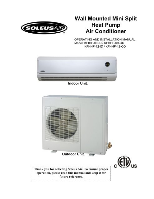
<strong>Wall</strong> <strong>Mounted</strong> <strong>Mini</strong> <strong>Split</strong><br />
<strong>Heat</strong> <strong>Pump</strong><br />
<strong>Air</strong> <strong>Conditioner</strong><br />
OPERATING AND INSTALLATION MANUAL<br />
Model: KFIHP-09-ID / KFHHP-09-OD<br />
KFHHP-12-ID / KFHHP-12-OD<br />
Indoor Unit.<br />
Outdoor Unit.<br />
Thank you for selecting Soleus <strong>Air</strong>. To ensure proper<br />
operation, please read this manual and keep it for<br />
future reference.
TABLE OF CONTENTS<br />
STRUCTURE AND OPERATION...……………………..……………………………………….....1-8<br />
Name of Each Part…………………………………………………………….………..………...……1<br />
The Instructions before Use…………………………………………………………………………2-3<br />
Specifications and Technical Data……………………………….……..……………….…………….4<br />
Remote Control Operation………………………………………………….….…...............………5-6<br />
How to Insert Batteries……………………………………………..………………….………...……7<br />
Operation………………………………………………………………………………………...……8<br />
INSTALLATION...……………………..……………………………………………………...........9-14<br />
Installation Location………………………………………………….………………………………9<br />
Electric Wiring………………………………………....………………………………...….……….10<br />
Grounding Requirement…………………………………………………….…...……..………....….10<br />
Installation Dimension Diagram……………………………………………………….…….………11<br />
Installation…………………………………………………………………………….……….....12-13<br />
Install the Indoor Unit…………………………………………………………………………….....14<br />
Install the Outdoor Unit……………………………………………………………………...…..15-16<br />
Test Operation and Check after Installation……………………………….………………………...17<br />
CARE AND MAINTENANCE……………………………………………...………..…….……...…18<br />
Care and Maintenance ………………………………………………………....………….…….18-19<br />
Trouble Shooting………………………………….………………………………………..……20-21<br />
ELECTRICAL SCHEMATIC DIAGRAM…………………………………...………..…………22-23<br />
Electrical Schematic Diagram (Indoor Unit)…………………………...……………......………….22<br />
Electrical Schematic Diagram (Outdoor Unit)………..……………………….……………………23<br />
WARRANTY…………………………………………………………………………………………24<br />
Danger Caution.<br />
This mark indicates a direction/procedure that<br />
must be followed!<br />
Thank you for selecting Soleus <strong>Air</strong>. To ensure proper operation, please read this<br />
manual and keep it for future reference.
Structure and Operation<br />
◆Name of Each Part<br />
- 1 -
◆The Instructions before Use<br />
★Grounding: The unit must be properly<br />
grounded.<br />
Warning<br />
★Disconnect the power when the unit is not being<br />
used for extended periods of time.<br />
★Don’t attempt to repair the air conditioner by<br />
yourself. There are no user replaceable parts.<br />
Please contact your authorized dealer.<br />
★If your air conditioner malfunctions,<br />
discontinue use and call your authorized dealer.<br />
★Never block the air inlet or outlet of indoor and<br />
outdoor unit.<br />
★Don’t step on the top of the outdoor unit or<br />
place something on it.<br />
★Never store flammable liquids near your air<br />
conditioner.<br />
★The condensing unit should be securely<br />
mounted to avoid damage.<br />
- 2 -
◆The Instructions before Use<br />
★Set the room temperature appropriately.<br />
The difference<br />
between indoor<br />
and outdoor<br />
temperature<br />
shall be 40 °F.<br />
★Adjust the air flow and direction properly.<br />
When the air conditioner is running, you can<br />
press the SWING key on the remote control to<br />
adjust the guide louver and change the<br />
direction of air flow.<br />
★Close all doors & windows for efficient<br />
operation.<br />
★To avoid harm to your pets or plants, never<br />
direct the airflow at them.<br />
★To avoid damage or electric shock, never spray<br />
liquid onto the unit.<br />
★This air conditioner cannot be used for<br />
drying clothes or refrigerating foods.<br />
- 3 -
◆Specification and Technical Data<br />
Function<br />
Accessory<br />
Model<br />
KFIHP-09-ID<br />
KFIHP-09-OD<br />
Cool / <strong>Heat</strong><br />
<strong>Air</strong> Cleaner<br />
KFHHP-12-ID<br />
KFHHP-12-OD<br />
Cooling capacity (Btu/h) 9000 12000<br />
<strong>Heat</strong>ing capacity (Btu/h) 9500 13000<br />
Power Supply (V) 115V~ 208~230<br />
Frequency (Hz) 60<br />
Cooling/<strong>Heat</strong>ing rated current(A) 12/13.6 9/10<br />
Cooling/<strong>Heat</strong>ing rated power(W) 1250/1450 1700/1750<br />
Cooling/<strong>Heat</strong>ing power input(W) 730/840 1100/1200<br />
Recycling air Volume(m 3 /h) 550<br />
Refrigerant and weight(lbs) R410A 2.6 lbs R410A 2.8 lbs<br />
Water proof level<br />
IP24<br />
Noise(Indoor/Outdoor)dB(A) 43/55<br />
Climate type<br />
Anti-electric shock protection<br />
Weight Indoor/Outdoor)(lbs) 24.3/99.2 24.3/99.2<br />
Dimensions<br />
(W x D x H)<br />
Indoor unit 30.31”×7.48”×9.84” 32.68”×8.86”×11.22”<br />
Outdoor unit 33.39”×12.6”×21.26” 33.39”×12.6”×21.26”<br />
Connection Pipe:<br />
Length (ft) 19.68<br />
Gas additional charge(oz/ft) 0.16<br />
Outer Diameter<br />
Liquid Pipe (mm)<br />
Φ6(1/4”)<br />
Gas Pipe (mm)<br />
Φ12(1/2”)<br />
Max Distance<br />
Height (ft) 16.4<br />
Length (ft) 49.21<br />
1. All above are tested and certified to ETL specification.<br />
2. All above could be changed without notice; the latest specifications are on the nameplate of your air conditioner.<br />
3. When the unit is restarted after it stopping, it can automatically resume the last running mode, and the outdoor unit<br />
starts later.<br />
Working temperature range:<br />
Indoor side DB/WB(°F) Outdoor side DB/WB(°F)<br />
Maximum cooling 89.6 / 73.4 109.4 / 78.8<br />
<strong>Mini</strong>mum cooling 69.8 / 59 69.8 / -<br />
Maximum heating 80.6 / - 75.2 / 64.4<br />
<strong>Mini</strong>mum heating 68 / - 23 / 21.2<br />
T1<br />
I<br />
- 4 -
◆Remote Control Operation<br />
Function-Remote control<br />
Note:<br />
• Don't drop the remote control.<br />
• Don't place the remote control in a location exposed to direct sunlight.<br />
• When the unit is restarted after stopped, it will automatically resume its last running mode, and the<br />
outdoor unit will start there after.<br />
TEMP+ TEMP- Button:<br />
Under the COOL, DRY,<br />
FAN or HEAT mode,<br />
press these two buttons<br />
could set the temperature,<br />
the temp. setting range is<br />
60.8°F -86°F, the temp.<br />
can be memorized under<br />
each mode.<br />
MODE Button:<br />
When the unit is<br />
turned on, press this<br />
button. The AUTO,<br />
COOL, DRY, FAN or<br />
HEAT mode can then<br />
be selected.<br />
FAN SPEED Button:<br />
When the unit starts up,<br />
under the AUTO, COOL,<br />
FAN or HEAT mode, press<br />
this button and select Auto<br />
fan, Low fan, Middle fan,<br />
High fan. At DRY mode,<br />
the fan speed runs at Low<br />
fan speed. The FAN<br />
SPEED can be memorized<br />
under various modes.<br />
SLEEP Button:<br />
Under COOL, DRY &<br />
HEAT mode, press the<br />
button once to start the<br />
SLEEP function, when<br />
pressed again, it will stop.<br />
CLOCK Button:<br />
When pressing this<br />
button once, the icon of<br />
CLOCK will flash, and<br />
can be adjusted. At<br />
CLOCK adjustment,<br />
press the TIME+ once,<br />
the ones placed on the<br />
minute will be increased<br />
1, and continuously press<br />
1 sec above, the tens<br />
place on the minute will<br />
be increased 1 in every<br />
half second. When<br />
pressing the TIME-, the<br />
ones placed on the<br />
minute will be decreased<br />
1, and continuously press<br />
1 sec above, the tens<br />
place will be decreased 1<br />
in every half second.<br />
After adjusting please<br />
press the CLOCK button<br />
again for confirming.<br />
- 5 -
◆Remote Control Operation (Continued)<br />
Liquid Crystal Display.<br />
It shows all set contents.<br />
ON/OFF Button<br />
Press ON.<br />
Press OFF.<br />
T-ON Button.<br />
When pressing this button<br />
once, enter into T-ON<br />
setting, the icon of T-ON<br />
flash, every press of<br />
TIME+, the time of T-ON<br />
will be increased 1min.<br />
When continuously press 1<br />
sec above, the tens placed<br />
on minute will be<br />
increased 1, every press of<br />
TIME- will be decreased 1<br />
minute, when continuously<br />
press 1 sec above, the tens<br />
placed on minute will be<br />
decrease 1 in every half<br />
second, and it goes round<br />
with 12 hours.<br />
TIME+ TIME- Button<br />
SWING Button:<br />
Press once to have louvers<br />
swing [oscillate]. Press<br />
twice in one second the<br />
panel light will turn on.<br />
Press twice again and the<br />
light will turn off.<br />
T-OFF Button<br />
Press this button once to<br />
enter into T-OFF<br />
setting, the icon of T-<br />
OFF will flash, the T-<br />
OFF button is available<br />
in ON or OFF mode, the<br />
setting method is the<br />
same with T-ON.<br />
CANCEL Button<br />
Pressing this button will<br />
cancel timer.<br />
Function instruction please<br />
refer to T-ON button, T-<br />
OFF button, CLOCK<br />
button.<br />
- 6 -
◆How to Insert Batteries<br />
1. Remove the cover from the back of the remote control.<br />
2. Insert the two batteries (Two AAA dry-cell batteries).<br />
3. Re-attach the cover.<br />
NOTE:<br />
• Don’t mix different batteries.<br />
• Remove batteries when not in use for a longtime.<br />
• The batteries can be used for about one year.<br />
• Keep remote at least 3.28 feet from TV’s and other electronic devices.<br />
When the wireless remote control is lost or broken, please use the manual switch,<br />
It will start in AUTO mode, the temperature setting and fan speed cannot<br />
be changed. Please use a ball point pen or similar device to operate switch.<br />
Turn on the unit: By pressing the Manual Switch the unit will start in AUTO automatically.<br />
The microcomputer will adjust to the indoor temperature by selecting (COOL, HEAT, FAN), in order to<br />
achieve a comfortable condition.<br />
• Turn off the unit: When unit is running, press the manual switch STOP button, the unit will stop running.<br />
- 7 -
◆Operation<br />
The general procedure:<br />
1. Power the unit and a buzzer will sound. Power/Run indication is red and the air conditioner is waiting<br />
to run.<br />
(Note: Once the air conditioner plugs to power supply or receives the signal of remote control, the<br />
buzzer will send out the desirable sound.)<br />
2. Press ON/OFF button, Power/Run indication is green and shows the running mode (Cooling, <strong>Heat</strong>ing,<br />
and Auto), and then the air conditioner starts running.<br />
3. Press MODE button to select desired running mode.<br />
4. Press SWING button to automatically swing and stop when repress it.<br />
5. Press FAN button to set desired fan speed.<br />
6. Press TEMP. button to set desired temperature.<br />
Procedure for SLEEP mode:<br />
7. Press SLEEP button to set the sleep.<br />
8. Press TIMER button to set the present ON TIME or OFF TIME.<br />
Note:<br />
In AUTO mode, the unit will automatically adjust its running modes according to the room temperature<br />
changes.<br />
- 8 -
Installation<br />
◆Installation Location<br />
Indoor Unit<br />
1. The inlet and outlet should not be covered so that the outflow air can reach all parts of the room.<br />
2. Install in a location from which the condensation water can be drained out conveniently and that is<br />
permitting easy connection with the outdoor unit.<br />
3. Avoid a location where there is heat source, steam or inflammable gas.<br />
4. Install in a location where it can withstand the full weight and vibration of the unit.<br />
5. Be sure to leave enough space to allow access for routine maintenance. The height of the installation<br />
should be 7.55 feet or more away from the floor.<br />
6. Install in a location where it is 3.28 feet or more away from other electric appliances such as television,<br />
audio devices, etc.<br />
7. Select a location where it is easy to remove and clean the filter.<br />
8. Be sure that the installation conforms to the installation dimension diagram.<br />
9. The plug should be accessible after the appliance is positioned.<br />
Outdoor Unit<br />
10. Select a location from which noise and outflow air emitted by unit will not inconvenience neighbors.<br />
11. Select a location where there should be sufficient ventilation.<br />
12. The inlet and outlet should not be covered.<br />
13. The location should be able to withstand the full weight and vibration of the outdoor unit and permit<br />
safe installation.<br />
14. There should be no danger of flammable gas or corrosive gas leaks.<br />
15. Be sure that the installation conforms to the installation dimension diagram.<br />
- 9 -
◆Electric Wiring<br />
1. All the electric work must be done according to the wiring diagram.<br />
2. Check for the correct voltage of the unit.<br />
3. Don’t pull the power cord strongly.<br />
4. The air conditioner must be safely grounded! Grounding wire must be connected to the building and<br />
done by the qualified personnel. In fixed circuit, there must be electricity leakage protection switch of<br />
enough power capacity and air switch with enough space. <strong>Air</strong> switch (thermal-magnetic breaker) can<br />
protect the short circuit and over load.<br />
◆Grounding Requirement<br />
1. The air conditioner is class 1 appliance, so it must connect with ground reliably.<br />
2. The yellow-green wires in the air conditioner are grounding wires and can’t be used for other purposes.<br />
3. The grounding-resistance should conform to the requirement of IEC Standard.<br />
- 10 -
◆Installation Dimension Diagram<br />
Important Notes<br />
The installation must be done by trained and qualified service personnel.<br />
112.6 inch<br />
212.6 inch<br />
- 11 -
◆Installation<br />
• Install the rear panel<br />
1. Always mount the rear panel horizontally.<br />
Because the mouth of drainage pipe is at the left<br />
side and the left side of the rear panel is better to<br />
adjust slightly lower.<br />
2. Fix the rear panel on the selected location with<br />
screws supplied with the unit.<br />
3. Be sure that the rear panel has been fixed firmly<br />
enough to withstand the weight of an adult of<br />
132.3 lbs; furthermore, the weight should be<br />
evenly shared by each screw.<br />
50 50<br />
• Install the piping hole<br />
1. Make the piping hole (Φ50) in the wall at a slight downward slant to the out door side. (Shown in<br />
Fig. 1)<br />
2. Insert the piping-hole sleeve into the hole to prevent the connection piping and wiring from being<br />
damaged when passing through the hole.<br />
• Install the drainage hose<br />
1. For well draining, the drain hose should be placed at a<br />
downward slant.<br />
2. Do not wrench or bend the drain hose or flood its end by<br />
water.<br />
3. The extended drainage pipe in the room should be wrapped<br />
with the insulating materials.<br />
• Install the connection pipes<br />
Connect the connection pipes with the relevant union pipes of the indoor unit and tighten the flare nut of the<br />
connection pipes (Shown in P16 “Install the connection pipes”).<br />
NOTE:<br />
1. Connect the connection pipes with the indoor unit first<br />
and the outdoor unit second.<br />
2. Be careful in bending the connection pipes, or you will<br />
damage the pipes.<br />
3. Do not over tighten the flare nut. There is a possibility<br />
of leakage.<br />
• Electric wiring<br />
1. Open the surface panel.<br />
2. Remove the fixed screw from the wiring cover as shown at the right side.<br />
3. Route the power connection cord from the back of the indoor unit and pull it toward the front through<br />
the wiring hole for connection.<br />
- 12 -
◆Installation<br />
4. Connect the Neutral wire of the power connection cables to the “N (1)” terminal of the terminal<br />
board, connect the Signal wire to the “2” terminal, and connect the live wire to the“3”terminal and<br />
connect the grounding wire to the “ ” terminal.<br />
5. Reassemble the wiring cover and tighten the screw.<br />
6. Recover the surface panel.<br />
- 13 -
◆ Install the Indoor Unit<br />
1. When routing the piping and wiring from the left or right side of the indoor unit, cut off the tailings from<br />
the chassis in necessary (shown in Fig.4 (a), (b) and (c)).<br />
(1) Cut off the tailings 1 when routing the wiring only.<br />
(2) Cut off the tailings 1 and tailings 2 (or tailings 1, tailings 2 and tailings 3) when routing both the<br />
wiring and piping.<br />
1, 2, and 3 in Fig. 4 are the recommended piping.<br />
2. Wrap the piping and wiring and pull them through the cut-off-tailings hole (Shown in Fig.5).<br />
3. Hang the mounting slots of the indoor unit on the upper tabs of the rear panel and check if it is secured.<br />
4. The height of the installed location should be 6.56 feet or more from the floor.<br />
- 14 -
◆Install the Outdoor Unit<br />
• Install the connection pipe<br />
1. Align the center of the piping flare with the valve.<br />
2. Screw in the flare nut by hand and then tighten<br />
the nut with spanner and torque wrench refer to<br />
right figure.<br />
Tightening Torque Table<br />
Hex Nut Diameter<br />
(mm)<br />
Tightening Torque<br />
(N.m)<br />
Φ6 15~20<br />
φ12 50~55<br />
Note: Exceeding tightening torque will<br />
damage the flare nut.<br />
• Electric wiring connection<br />
1. Disassemble the big handle.<br />
2. Remove the wire clamp and connect the end of<br />
the power connection cord with screws to the<br />
wiring terminal board. Be sure that the wiring<br />
connection is in accordance with the indoor unit’s.<br />
3. Fix the wiring with wire clamp. For the heat<br />
pump join the two control cords.<br />
4. Make sure that the wiring has been connected securely.<br />
5. Reassemble the big handle.<br />
NOTE:<br />
1. Incorrect wiring connections will cause electrical malfunction.<br />
2. Do not pull the wire when assembling it with wire clamp.<br />
- 15 -
◆Install the Outdoor Unit<br />
• <strong>Air</strong> Purging and Leakage Test<br />
1. Remove the flare nuts of charging end from gas valve.<br />
2. Connect the charging hose in the middle to the vacuum<br />
pump, then Low-pressure (Lo) end should be connected<br />
to charging end of gas valve. (Shown in Fig. 9)<br />
3. Open the vacuum pump to evacuate. When multi-meter<br />
indicates 1 bar, fully tighten Lo handle of manifold valve<br />
and stop evacuation. Keep it for over 15 minutes to ensure<br />
the pressure is constant.<br />
4. Remove bonnets of gas and liquid valve.<br />
5. Slightly loosen core of liquid valve with hexagon wrench<br />
until the pressure exceeds 0 bars.<br />
6. Remove charging hose from charging end of gas valve and<br />
screw the flare nuts of charging end.<br />
7. Open cores of gas and liquid valve entirely by hexagon<br />
wrench.<br />
8. Tighten the bonnets of gas and liquid valve, and then test<br />
whether there is any leakage or not.<br />
- 16 -
◆Test Operation and Check after Installation<br />
Test Operation<br />
1. Before Test Operation<br />
(1) Do not switch on power before installation is finished<br />
completely.<br />
(2) Electric wiring must be connected correctly and securely<br />
(3) Cut-off valves of the connection pipes should be opened.<br />
(4) All the impurities such as scraps must be cleared from the<br />
unit.<br />
2. Test Operation Method<br />
(1) Switch on power and press “ON/OFF” button on the remote control to run the air<br />
conditioner.<br />
(2) Press “MODE” button and check the operation condition of COOL, HEAT, SWING mode<br />
and so on.<br />
If Wireless remote control is lost, open the surface panel and operate as following:<br />
a. When turning it to Auto position, unit will run in Auto mode, if there is remote control signal, it will run<br />
at the remote control signal.<br />
b. When turning it to Test position, the main unit will enter into Cool mode, indoor fan will run at high fan<br />
speed, if there is remote control signal, main unit will run at the remote control signal.<br />
c. When turning it to Run position, the main unit will run at received remote control order.<br />
d. When turning it to Stop position, the unit will stop running.<br />
Check after Installation<br />
Items to be checked<br />
Has it been properly mounted?<br />
Have you done the refrigerant leakage test?<br />
Does the unit drain well?<br />
Is the voltage in accordance with the rated<br />
voltage marked on the nameplate?<br />
Is the electric wiring and piping connection<br />
installed correctly and securely?<br />
Has the unit been connected to secure grounding<br />
connection?<br />
Has the inlet and outlet been insulated?<br />
Has the length of connection pipes and refrigerant<br />
capacity been recorded?<br />
Possible Malfunction<br />
The unit may drop, shake or emit noise.<br />
It may cause insufficient cooling (heating) capacity.<br />
It may cause condensation and dripping.<br />
It may cause electric malfunction or damage the part.<br />
It may cause electric malfunction or damage the unit.<br />
It may cause electrical leakage.<br />
It may cause insufficient cooling (heating) capacity.<br />
The refrigerant capacity is not accurate.<br />
- 17 -
Care and Maintenance<br />
◆Care and Maintenance<br />
CAUTION:<br />
Turn power off and pull out the power cord before cleaning air conditioner.<br />
Never sprinkle water on the indoor unit and the outdoor unit for cleaning because it can<br />
cause an electric shock.<br />
Volatile Liquid (e.g. thinner or gasoline) will damage the air conditioner. (So wipe the<br />
units with a dry soft cloth, or a cloth slightly moistened with water or cleanser.)<br />
Clean the front panel (Don’t remove the front panel when cleaning)<br />
When the indoor unit front panel is dirty, please use the cloth which is soaked in the warm water<br />
under 104°F, then dry it and wipe the dirty places.<br />
NOTE:<br />
There are microcomputer components and circuit board on the displayer of the indoor unit front<br />
panel, never let it dip in the water.<br />
Cleaning the <strong>Air</strong> Filters (Recommended once every three months)<br />
The air filters should be cleaned more frequently in dusty conditions.<br />
1. Take down the air filter<br />
Open the surface panel, hold the tab of air filter<br />
and raise it slightly, and then take it out along the<br />
direction of arrows (See the right figure).<br />
2. Cleaning<br />
To clear the dust adhering to the filters, you can<br />
either use a vacuum cleaner, or wash them with<br />
water and dry it in the shade (See the right<br />
figure).<br />
Note: Never use water above 113°F to wash the filters, or<br />
it could cause deformation or discoloration. Never parch it<br />
by fire, or it could cause a fire or deformation.<br />
- 18 -
◆Care and Maintenance (Continued)<br />
3. Reinsert the filters<br />
Reinsert the filters along the direction of arrow,<br />
then cover the surface panel and clasp it.<br />
Check before Use<br />
1. Be sure that nothing obstructs the air outlet and<br />
intake vents.<br />
2. Verify that the unit is properly grounded.<br />
3. Always use new batteries.<br />
4. Verify condenser is properly mounted.<br />
Maintain after Use<br />
1. Clean filters and other parts.<br />
2. Turn main power off.<br />
3. Clean dust from the outdoor unit.<br />
◆Trouble Shooting<br />
Warning: Don’t attempt to repair the air conditioner by yourself; it can cause an electric shock or fire.<br />
Please check the following items before calling your service technician.<br />
Problem<br />
Trouble Shooting<br />
Won’t start immediately<br />
when the air conditioner is<br />
restarted.<br />
Once the air conditioner is stopped, it will not<br />
operate until the time delay of 3 minutes has<br />
passed.<br />
There’s unusual odor<br />
blowing from the outlet after<br />
operation is started.<br />
This is caused by the odors in the room.<br />
- 19 -
◆Trouble Shooting<br />
Problem<br />
Sound of water flow can be heard during operation.<br />
Trouble Shooting<br />
This is caused by the refrigerant flowing inside<br />
the unit.<br />
Mist is emitted during cooling operation.<br />
Because the air of the room is cooled down<br />
rapidly.<br />
Creaking noise can be heard when start or stop the unit.<br />
This is caused by the expansion of plastic due<br />
to the change of temperature.<br />
<strong>Air</strong> conditioner does not operate at all.<br />
Cooling (<strong>Heat</strong>ing) efficiency is not good.<br />
Remote control is not operating<br />
• Has the power been shut down?<br />
• Is the wiring loose?<br />
• Is the leakage protection switch in<br />
operation?<br />
• Is TIMER ON is operation?<br />
• Is SET TEMP. suitable?<br />
• Is air inlet or outlet obstructed?<br />
• Are air filters dirty?<br />
• Are the windows and door closed?<br />
• Is indoor fan speed set at low speed?<br />
• Is there any other hear source in your room?<br />
• Remote control can’t be used when the air<br />
conditioner is disturbed or changing its<br />
functions frequently.<br />
• Is the remote control out of effective to the<br />
indoor unit? Are there any obstruction<br />
between the remote control and the signal<br />
receptor?<br />
• Replace the worn batteries of remote control<br />
is the voltage of the batteries is not<br />
sufficient.<br />
- 20 -
◆Trouble Shooting<br />
Immediately discontinue using the unit and disconnect the power if any of the following occurs:<br />
Unusual noise can be heard during operation.<br />
<strong>Air</strong> switch or leakage protection switch often<br />
shuts down.<br />
Water is leaking from the unit.<br />
Electrical lines and power plug are very hot<br />
or smoking.<br />
Wind blowing from the outlet smells terrible<br />
during operation.<br />
If you have any<br />
question, please call<br />
your contractor or<br />
service dept.<br />
- 21 -
Electrical Schematic Diagram<br />
◆Electrical Schematic Diagram (Indoor Unit)<br />
Please Insert Diagram in here.<br />
- 22 -
◆Electrical Schematic Diagram (Outdoor Unit)<br />
Please Insert Diagram in here.<br />
- 23 -
Warranty<br />
Soleus International Inc. warrants the accompanying Soleus <strong>Air</strong> <strong>Wall</strong> <strong>Mounted</strong> <strong>Mini</strong> <strong>Split</strong> <strong>Heat</strong> <strong>Pump</strong> <strong>Air</strong><br />
<strong>Conditioner</strong> (KFIHP-09-ID/KFIHP-09-OD; KFHHP-12-ID/KFHHP-12-OD) to be free of defects in material<br />
and workmanship for the applications specified in its operation instruction for the period of labor and parts<br />
specified below.<br />
5 YEARS FOR COMPRESSOR<br />
1 YEAR FOR OTHER COMPONENTS<br />
This warranty shall not apply to broken or marred cabinets, accessories, knobs, filters or routine<br />
maintenance. This warranty does not apply to uncrating, setup, installation, removal of the product for<br />
repair or reinstallation of the product after repair.<br />
This warranty does not apply to repairs or replacements necessitated by any cause beyond the control of<br />
Soleus International including, but not limited to, any malfunction, defect or failure caused by or resulting<br />
from unauthorized service or parts, improper maintenance, operation contrary to furnished instructions,<br />
shipping or transit accidents, modification or repair by the user, abuse, misuse, neglect, accident, incorrect<br />
power line voltage, fire, flood or other Acts of God, or normal wear and tear.<br />
Warranty service must be performed by a qualified HVAC contractor. Soleus maintains a centralized<br />
service network to provide parts and assist in resolving service problems if difficulties are encountered.<br />
Soleus agrees to provide service information, sell repair parts and reimburse the dealer /servicer for parts<br />
and services in accordance with Soleus International’s Policies and Procedures.<br />
SOLEUS INTERNATIONAL MAINTAINS THAT ALL WARRANTIES, INCLUDING IMPLIED<br />
WARRANTY OR MERCHANTABILITY ARE LIMITED TO THE TERMS AND CONDITIONS<br />
SPECIFIED ABOVE. SOLEUS INTERNATIONAL DISCLAIMS ANY LIBILITY FOR<br />
CONSEQUENTIAL OR INCIDENTAL DAMAGES AND IN NO EVENT SHALL SOLEUS<br />
INTERNATIONAL INC.’S LIABILITY EXCEED THE RETAIL VALUE OF THE AIR<br />
CONDITIONER.<br />
This warranty covers only new products purchased from our authorized dealers or retailers. It does not cover<br />
used, internet sales, salvaged, or refurbished products.<br />
FOR TECHNICAL SUPPORT AND WARRANTY SERVICE<br />
Soleus International Inc.<br />
Tel: 1-888-8 SOLEUS<br />
Monday through Friday, 9:00 AM to 5:00 PM, PST<br />
Email: Contact@soleusair.com<br />
Website: www.soleusair.com<br />
- 24 -
![Owner's Manual (General) [pdf] - Appliance Factory Parts](https://img.yumpu.com/50830858/1/184x260/owners-manual-general-pdf-appliance-factory-parts.jpg?quality=85)