200 Series Owners Manual - Audio-Technica
200 Series Owners Manual - Audio-Technica
200 Series Owners Manual - Audio-Technica

Create successful ePaper yourself
Turn your PDF publications into a flip-book with our unique Google optimized e-Paper software.
Transmitter Setup<br />
Battery Selection and Installation<br />
An alkaline 9-volt battery is recommended. Make certain the<br />
transmitter power switch is Off before installing or changing<br />
batteries.<br />
When inserting the battery, observe correct polarity as marked<br />
inside the battery compartment. The transmitter housings are<br />
designed to prevent incorrect installation of the battery; do not<br />
force the battery in. Reversed batteries may cause damage to<br />
the transmitter.<br />
UniPak Transmitter Battery Installation<br />
1. Slide off the battery cover as shown in Figure D.<br />
2. Carefully insert a fresh 9V alkaline battery, observing polarity<br />
markings.<br />
3. Replace the battery cover (Fig. E).<br />
Handheld Transmitter Battery Installation<br />
1. While holding the upper part of the transmitter body just<br />
below the ball-screen, unscrew the lower body cover and<br />
slide it downward to expose the battery compartment<br />
(Fig. F). Do not attempt to pull the lower body farther<br />
down, or to gain access to the electronics.<br />
UniPak Transmitter Input Connection<br />
Connect an audio input device (microphone or guitar cable) to the<br />
input connector on the bottom of the transmitter. The<br />
cable connector latches automatically when inserted into the<br />
transmitter jack. To unlatch and remove the connector, simply pull<br />
up on the connector’s knurled metal collar.<br />
A number of <strong>Audio</strong>-<strong>Technica</strong> professional microphones and<br />
cables are available separately, pre-terminated with a UniPak<br />
input connector (see “Optional System Accessories” on<br />
page 9).<br />
Transmitting Antenna<br />
The UniPak transmitter includes a permanently attached flexible<br />
antenna. For best results, allow the antenna to hang freely and full<br />
length from the bottom of the transmitter. If the received signal is<br />
marginal, experiment with different transmitter<br />
positions on your body or instrument; or try repositioning the<br />
receiver. Do not attempt to remove, replace or change the<br />
length of the transmitting antenna.<br />
2. Lift the white “battery keeper” arm until it sticks straight out<br />
from the mic body (no higher). Then carefully insert a fresh<br />
9V alkaline battery, observing polarity markings.<br />
3. Screw the body back together. Do not overtighten.<br />
Battery Condition Indicator<br />
The red battery condition indicator (Fig. H/I) should light strongly<br />
with a fresh battery. As the battery weakens, the indicator will<br />
grow dimmer. When the indicator becomes very dim or goes out,<br />
there is little life left in the battery. Replace it at once for continued<br />
operation of the transmitter.<br />
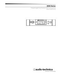
All transmitters feature battery-save switches (Fig. D/F). As<br />
supplied, the switch is set in the High position for maximum<br />
range. Switching to the Low position increases battery life by<br />
reducing power. (Note: Effective range decreases when the<br />
switch is set in Low position.)<br />
6<br />
See pages 2-3 for illustrations.