200 Series Owners Manual - Audio-Technica
200 Series Owners Manual - Audio-Technica
200 Series Owners Manual - Audio-Technica

You also want an ePaper? Increase the reach of your titles
YUMPU automatically turns print PDFs into web optimized ePapers that Google loves.
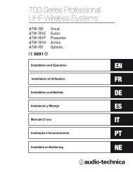
<strong>200</strong> <strong>Series</strong> Professional<br />
VHF Wireless Systems<br />
ATW-251<br />
ATW-251/G<br />
ATW-251/H<br />
ATW-251/L<br />
ATW-252<br />
Options<br />
Guitar<br />
Active<br />
Presenter<br />
Vocal<br />
0891<br />
!<br />
Installation and Operation
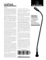
Antennas<br />
Figure A (p. 3)<br />
Receiver Controls and Functions<br />
Figure B - Front panel controls and functions<br />
1a<br />
2 3 4<br />
1b<br />
Figure C - Rear panel controls and functions<br />
5 6<br />
7 8<br />
2
Transmitter Controls and Functions<br />
Microphone<br />
Trimmer (MT)<br />
Guitar Trimmer<br />
(GT)<br />
➞<br />
➞<br />
Figure D<br />
Battery-Save Switch<br />
(under screwdriver clip)<br />
Battery Polarity<br />
Diagram<br />
Figure E<br />
Battery Polarity<br />
Diagram<br />
Battery-Save<br />
Switch<br />
Figure F<br />
Gain Trimmer<br />
Figure G<br />
Screwdriver<br />
Power Switch<br />
Off/Standby/On<br />
Battery Condition<br />
Indicator<br />
Battery Condition<br />
Indicator<br />
BATT.<br />
INPUT<br />
OFF ST ON<br />
POWER BATT. ANT<br />
ST.BY<br />
ON OFF<br />
Input<br />
Connector<br />
Figure H<br />
Antenna<br />
Figure I<br />
Power Switch<br />
On/Standby/Off<br />
3
Professional VHF Wireless Systems<br />
Installation and Operation<br />
This device complies with the European R&TTE Directive.<br />
Operation is subject to the condition that this device does not<br />
cause harmful interference.<br />
CAUTION! Electrical shock can result from removal of the<br />
receiver cover. Refer servicing to qualified service personnel.<br />
No user-serviceable parts inside. Do not expose to rain or<br />
moisture.<br />
The circuits inside the receiver and transmitter have been<br />
precisely adjusted for optimum performance and compliance<br />
with federal regulations. Do not attempt to open the receiver<br />
or transmitter. To do so will void the warranty, and may cause<br />
improper operation.<br />
Notice to individuals with implanted cardiac pacemakers<br />
or AICD devices:<br />
Any source of RF (radio frequency) energy may interfere with<br />
normal functioning of the implanted device. All wireless<br />
microphones have low-power transmitters (less than 0.05 watts<br />
output) which are unlikely to cause difficulty, especially if they<br />
are at least a few inches away. However, since a “body-pack”<br />
mic transmitter typically is placed against the body, we suggest<br />
attaching it at the belt, rather than in a shirt pocket where it may<br />
be immediately adjacent to the medical device. Note also that<br />
any medical-device disruption will cease when the RF<br />
transmitting source is turned off. Please contact your physician<br />
or medical-device provider if you have any questions, or<br />
experience any problems with the use of this or any other RF<br />
equipment.<br />
Introduction<br />
Thank you for choosing an <strong>Audio</strong>-<strong>Technica</strong> professional wireless<br />
system. You have joined thousands of other satisfied customers<br />
who have chosen our products because of their quality,<br />
performance and reliability. This wireless microphone system<br />
is the successful result of years of design and manufacturing<br />
experience.<br />
Each <strong>200</strong> <strong>Series</strong> professional VHF wireless system includes a<br />
receiver and either a body-pack transmitter or a handheld<br />
microphone/transmitter on a specific crystal-controlled<br />
frequency. ATW-T201 UniPak body-pack transmitter systems<br />
include models pre-packaged with an AT8319 guitar cable (/G),<br />
a PRO 8HEcW headworn microphone (/H), or a<br />
lavalier mic (/L) for particular applications. All A-T Wireless<br />
Essentials ® microphones and cables, available separately, are preterminated<br />
for use with any <strong>200</strong> system.<br />
Because <strong>200</strong> <strong>Series</strong> packaging is designed to hold all versions of<br />
the system, some compartments in the carton are<br />
intentionally left empty.<br />
The versatile ATW-T201 UniPak body-pack transmitter has both a<br />
high-impedance input for instruments, and a low-impedance input<br />
with bias connection for use with dynamic and electret condenser<br />
microphones. The ATW-T202 handheld transmitter features a<br />
unidirectional dynamic microphone element.<br />
Both the body-pack and handheld transmitters use internal<br />
9-volt batteries and have Off/Standby/On switches, input Trim<br />
(level) adjustments and battery-save switches.<br />
About RF Interference:<br />
Please note that wireless frequencies are shared with other<br />
radio services<br />
Please make certain, that you follow the national regulations of<br />
the country where you are planning to use the system<br />
If you need help with operation or frequency selection, please<br />
contact your local dealer or <strong>Audio</strong>-<strong>Technica</strong>. Extensive<br />
wireless information is also available on www.audiotechnica.com.<br />
“CAUTION! Do not expose batteries to excessive heat, such<br />
as direct sunlight or open fires.”<br />
4<br />
See pages 2-3 for illustrations.
Receiver Installation<br />
Location<br />
For best operation the receiver should be at least 3' (1 m) above<br />
the ground and at least 3' (1 m) away from a wall or metal surface<br />
to minimize reflections. Keep the receiver<br />
antennas away from noise sources such as digital equipment,<br />
motors, automobiles and neon lights, as well as away from large<br />
metal objects. In multi-channel systems, position receivers at<br />
least 3' (1 m) apart and keep operating<br />
transmitters at least 6' (2 m) from the receivers to help assure<br />
maximum RF performance.<br />
Output Connection<br />
The receiver provides unbalanced, aux-level output from a 1 /4" TS<br />
(“mono”) phone jack; an output cable is not included. Use<br />
a shielded audio cable with 1 /4" phone plug to connect the<br />
receiver’s AF Out jack to the mixer/amplifier’s aux-level input.<br />
Power Connection<br />
Connect the DC plug on the included AC power adapter to the<br />
DC power input on the back of the receiver. Secure the cord over<br />
the cord hook on the back of the receiver, to keep the plug from<br />
being detached by an accidental tug on the cord. Then plug the<br />
adapter into a standard 230 Volt 50 Hz AC power outlet.<br />
A novel “dipole” antenna system on the receiver improves<br />
operation by providing a “ground” element in addition to the<br />
usual “signal” element. Position the two antennas at 90° in the<br />
form of a “V,” or position the left (“signal”) antenna vertically and<br />
the right (“ground”) antenna horizontally, in the shape of<br />
an “L” (Fig. A). Use the position that performs better in your<br />
operating environment. Be certain to extend both antennas to<br />
their full 15" (38 cm) length by holding them at their bases and<br />
pulling out on their caps. Both antenna elements may be<br />
swiveled to the left and right, but do not attempt to rotate them in<br />
a screwing/unscrewing motion. To do so may damage the<br />
antenna and/or receiver. For best performance, locate the<br />
receiver so its antennas are in direct line-of-sight to the<br />
transmitter's likely operating position.<br />
Front Panel Controls and Functions (Fig. B)<br />
(Note that the receiver has no power Off/On switch. The receiver<br />
will be energized whenever the power adapter is<br />
connected and plugged into the AC outlet. Unplug the power<br />
supply from the AC outlet when the system is not in use – both<br />
for safety, and to conserve energy.)<br />
Antennas<br />
Receiver Controls and Functions<br />
1. ANTENNAS: Position the “signal” antenna (1a) and<br />
“ground” antenna (1b) as shown in Figure A.<br />
2. POWER INDICATOR: Lights when power is supplied to<br />
the receiver.<br />
3. RF INDICATOR: Lights to show presence of transmitter<br />
signal.<br />
4. AF PEAK INDICATOR: Only lights when audio distortion<br />
is present at maximum modulation. Not affected by<br />
position of Volume control.<br />
Rear Panel Controls and Functions (Fig. C)<br />
5. AUDIO OUTPUT JACK: 1 /4" TS (Tip-Sleeve) or “mono”<br />
phone jack. Use a shielded cable to connect to an<br />
unbalanced aux-level input of a mixer or amplifier.<br />
6. VOLUME CONTROL: Adjusts the audio level at the 1 /4"<br />
output jack. Does not affect AF Peak indicator.<br />
7. CORD HOOK: Loop the cord around the cord hook to keep<br />
the DC plug from pulling out accidentally.<br />
8. POWER INPUT JACK: Connect the DC plug from the<br />
included AC adapter.<br />
5
Transmitter Setup<br />
Battery Selection and Installation<br />
An alkaline 9-volt battery is recommended. Make certain the<br />
transmitter power switch is Off before installing or changing<br />
batteries.<br />
When inserting the battery, observe correct polarity as marked<br />
inside the battery compartment. The transmitter housings are<br />
designed to prevent incorrect installation of the battery; do not<br />
force the battery in. Reversed batteries may cause damage to<br />
the transmitter.<br />
UniPak Transmitter Battery Installation<br />
1. Slide off the battery cover as shown in Figure D.<br />
2. Carefully insert a fresh 9V alkaline battery, observing polarity<br />
markings.<br />
3. Replace the battery cover (Fig. E).<br />
Handheld Transmitter Battery Installation<br />
1. While holding the upper part of the transmitter body just<br />
below the ball-screen, unscrew the lower body cover and<br />
slide it downward to expose the battery compartment<br />
(Fig. F). Do not attempt to pull the lower body farther<br />
down, or to gain access to the electronics.<br />
UniPak Transmitter Input Connection<br />
Connect an audio input device (microphone or guitar cable) to the<br />
input connector on the bottom of the transmitter. The<br />
cable connector latches automatically when inserted into the<br />
transmitter jack. To unlatch and remove the connector, simply pull<br />
up on the connector’s knurled metal collar.<br />
A number of <strong>Audio</strong>-<strong>Technica</strong> professional microphones and<br />
cables are available separately, pre-terminated with a UniPak<br />
input connector (see “Optional System Accessories” on<br />
page 9).<br />
Transmitting Antenna<br />
The UniPak transmitter includes a permanently attached flexible<br />
antenna. For best results, allow the antenna to hang freely and full<br />
length from the bottom of the transmitter. If the received signal is<br />
marginal, experiment with different transmitter<br />
positions on your body or instrument; or try repositioning the<br />
receiver. Do not attempt to remove, replace or change the<br />
length of the transmitting antenna.<br />
2. Lift the white “battery keeper” arm until it sticks straight out<br />
from the mic body (no higher). Then carefully insert a fresh<br />
9V alkaline battery, observing polarity markings.<br />
3. Screw the body back together. Do not overtighten.<br />
Battery Condition Indicator<br />
The red battery condition indicator (Fig. H/I) should light strongly<br />
with a fresh battery. As the battery weakens, the indicator will<br />
grow dimmer. When the indicator becomes very dim or goes out,<br />
there is little life left in the battery. Replace it at once for continued<br />
operation of the transmitter.<br />
All transmitters feature battery-save switches (Fig. D/F). As<br />
supplied, the switch is set in the High position for maximum<br />
range. Switching to the Low position increases battery life by<br />
reducing power. (Note: Effective range decreases when the<br />
switch is set in Low position.)<br />
6<br />
See pages 2-3 for illustrations.
System Operation<br />
Turn down the receiver volume control and the mixer/amplifier<br />
level before starting up the wireless system. Do not switch on<br />
the transmitter yet.<br />
Receiver on...<br />
Plug the power supply into an AC power source. The green Power<br />
indicator on the front panel will light.<br />
Transmitter on...<br />
When the transmitter is switched on, the receiver’s yellow RF<br />
signal indicator will light. The transmitters have a 3-position power<br />
switch. When the switch is set to “Standby” (ST or ST.BY), the<br />
transmitter produces RF with no audio signal. When the switch is<br />
“On,” the transmitter produces both RF and audio. Excessive<br />
audio input to the transmitter will cause the receiver’s red AF<br />
Peak indicator to light.<br />
Receiver Volume<br />
Under typical operating conditions, the receiver's volume<br />
control should be turned all the way up, with overall system audio<br />
gain adjusted at the mixer or amplifier.<br />
Input Level Adjustment<br />
Input trimmer controls in the transmitters enable you to<br />
maximize performance for a particular microphone or guitar<br />
sensitivity, or to adjust for different acoustic input levels.<br />
Adjusting Input Level - UniPak Transmitter<br />
Slide the battery cover off the top part of transmitter and remove<br />
the screwdriver from its clip (Fig. D). Gently turn both the “MT”<br />
(Mic Trimmer) and “GT” (Guitar Trimmer) controls to their full<br />
counterclockwise positions (toward “LO”).<br />
• Microphone: Adjusting input level<br />
Gently turn only the “MT” (Mic Trimmer) control all the way<br />
up (clockwise, toward “Hi”). Check for excessive gain by<br />
speaking/singing into the microphone at typically loud levels while<br />
watching the receiver’s AF Peak indicator. If the AF Peak indicator<br />
does light, turn the MT control slightly counterclockwise until the<br />
AF Peak indicator no longer lights with maximum audio input to<br />
the transmitter.<br />
• Guitar: Adjusting input level<br />
Gently turn only the “GT” (Guitar Trimmer) control all the way up<br />
(clockwise, toward “Hi”). Check for excessive gain by<br />
playing at typically loud levels while watching the receiver’s AF<br />
Peak indicator. If the AF Peak indicator does light, turn the GT<br />
control slightly counterclockwise until the AF Peak indicator no<br />
longer lights with maximum instrument input to the transmitter.<br />
After adjusting input level, return the screwdriver to its clip<br />
and reinstall the battery cover. No further transmitter gain<br />
adjustments should be needed, as long as the input device<br />
and the acoustic input level are not changed.<br />
Adjusting Input Level - Handheld Transmitter<br />
Unscrew the lower body cover and slide it downward, exposing<br />
the screwdriver and Gain Trimmer control (Fig. G). Remove the<br />
screwdriver from its clip. Gently turn the control to its full<br />
clockwise position (toward the side marked “H”), the factory<br />
setting. Check for excessive gain by speaking/singing into the<br />
microphone at typically-loud levels while watching the receiver’s<br />
AF Peak indicator. If the AF Peak indicator does light, turn the Gain<br />
Trimmer control slightly counterclockwise until the AF Peak<br />
indicator no longer lights with maximum audio input to the<br />
mic/transmitter.<br />
Return the screwdriver to its clip and close and secure the lower<br />
body. No further transmitter gain adjustments should<br />
be needed, as long as the acoustic input does not change<br />
significantly.<br />
CAUTION! The small trimmer controls are delicate; use<br />
only the supplied screwdriver. Do not force the trimmers<br />
beyond their normal 190 o range of rotation.<br />
Return the screwdriver to its storage clip when not in use.<br />
Ten Tips To Obtain The Best Results<br />
1. Use only fresh alkaline batteries. Do not use “general purpose”<br />
(carbon-zinc) batteries.<br />
2. Position the receiver so that it has the fewest possible<br />
obstructions between it and the normal location of the transmitter.<br />
Line-of-sight is best.<br />
3. The transmitter and the receiver should be as close together as<br />
conveniently possible, but not less than 6' (2 m).<br />
4. Do not place the receiver antennas within 3' (1 m) of another<br />
receiver or antenna.<br />
5. The receiver antennas should be kept away from any metal.<br />
6. A receiver cannot receive signals from two transmitters at the<br />
same time.<br />
7. In the UniPak transmitter, the “MT” or “GT” input control not<br />
in use should be set to minimum.<br />
8. If the receiver output is set too low, the overall signal-to-noise ratio<br />
of the system may be reduced. Conversely, if the volume control<br />
of the receiver is set too high, it may over-drive the input of the<br />
mixer/amplifier, causing distortion. Adjust the output level of the<br />
receiver so the highest sound pressure level going into the<br />
microphone (or the loudest instrument playing level) causes no<br />
input overload in the mixer, and yet permits the mixer level<br />
controls to operate in their “normal” range (not set too high or<br />
too low). This provides the optimum signal-to-noise for the<br />
entire system.<br />
9. Turn the transmitter off when not in use. Remove the battery if<br />
the transmitter is not to be used for a period of time.<br />
10. Unplug the receiver from the AC outlet when the system is not<br />
in use.<br />
7
System Operating Frequencies<br />
Frequency Selection<br />
Each transmitter/receiver system operates on a single factory<br />
aligned, crystal-controlled frequency. Available frequencies are<br />
shown in the chart below.<br />
The frequency of each transmitter appears on a label on the<br />
outside of the unit. The frequency of each receiver appears on a<br />
label on the rear panel of the unit and the frequency of each<br />
system appears on the outer carton. For future reference, please<br />
record them in the space provided below.<br />
RF Interference<br />
Please note that wireless frequencies are shared with other radio<br />
services. According to national regulations, “Wireless<br />
microphone operations are unprotected from interference from<br />
other licensed operations within the band. If any interference<br />
is received by any Government or non-Government operation, the<br />
wireless microphone must cease operation...”<br />
If you need assistance with operation or frequency selection,<br />
please contact your dealer or the A-T professional division.<br />
Extensive wireless information also is available on the A-T Web<br />
site at www.audio-technica.com.<br />
Freq. (MHz)<br />
173.800 MHz - 174.600 MHz - 175.000 MHz<br />
Systems on these frequencies may be combined for up to three simultaneous operating<br />
channels.<br />
For future reference, please record your system information here<br />
(the serial numbers appear near the screwdriver clip in each transmitter,<br />
and on the bottom of each receiver):<br />
Operating Frequency<br />
Frequency • MHz<br />
Receiver<br />
Model ATW-R250<br />
Serial Number<br />
Transmitter<br />
Model ATW-T20<br />
1/2<br />
Serial Number<br />
8
Specifications †<br />
OVERALL SYSTEM<br />
Operating Frequency<br />
VHF high band, 173 MHz to 175 MHz<br />
Frequency Stability ±0.005%<br />
Modulation Mode<br />
FM<br />
Maximum Deviation<br />
±15 kHz<br />
Operating Range<br />
70m typical<br />
Operating Temperature Range 40° F (4° C) to 110° F (43° C)<br />
Frequency Response<br />
80 Hz to 13 kHz<br />
RECEIVER<br />
Receiving System<br />
Image Rejection<br />
Signal-to-noise Ratio<br />
Total Harmonic Distortion<br />
Sensitivity<br />
<strong>Audio</strong> Output<br />
Output Connector<br />
Power Supply<br />
Dimensions<br />
Net Weight<br />
Accessories Included<br />
Non-diversity, single-channel,<br />
dual antenna system<br />
50 dB minimum<br />
80 dB at 10 kHz deviation (IEC-weighted),<br />
maximum modulation 15 kHz<br />
≤1% (10 kHz deviation at 1 kHz)<br />
20 dBµV for 60 dB S/N (IEC-weighted)<br />
350 mV (1 kHz modulation, 10 kHz<br />
deviation, 100k ohm load)<br />
1<br />
/4" TS (“mono”) phone jack<br />
230V AC (50Hz) to 12V DC 500mA<br />
(centre positive) external power supply.<br />
190.0 mm W x 42.0 mmH x<br />
130.0 mm D<br />
311 grams<br />
Power supply<br />
UNIPAK TRANSMITTER<br />
RF Power Output<br />
Spurious Emissions<br />
Dynamic Range<br />
Input Connections<br />
Battery (not included)<br />
Current Consumption<br />
Battery Life<br />
Dimensions<br />
Net Weight (without battery)<br />
HANDHELD TRANSMITTER<br />
RF Power Output<br />
Spurious Emissions<br />
Dynamic Range<br />
Microphone Element<br />
Battery (not included)<br />
Current Consumption<br />
Battery Life<br />
Dimensions<br />
Net Weight (without battery)<br />
Accessory Included<br />
High: 10 mW; Low: 2 mW, typical<br />
According to National Regulations<br />
≥90 dB, A-weighted<br />
High impedance, low impedance, bias<br />
9V (NEDA type 1604) alkaline<br />
30 mA typical<br />
Approximately 15 hours (High);<br />
20 hours (Low), depending on battery type<br />
and use pattern<br />
65.0 mm W x 110.0 mm H<br />
x 25.4 mm D<br />
78 grams<br />
High: 10 mW; Low: 2 mW, typical<br />
Under Federal Regulations<br />
≥90 dB, A-weighted<br />
Dynamic unidirectional<br />
9V (NEDA type 1604) alkaline<br />
30 mA typical<br />
Approximately 15 hours (High);<br />
20 hours (Low), depending on battery type<br />
and use pattern<br />
241.3 mm long, 53.3 mm<br />
maximum diameter<br />
360 grams<br />
AT8456a Quiet-Flex stand clamp<br />
Optional System Accessories<br />
†<br />
In the interest of standards development, A.T.U.S. offers full details on its test methods to<br />
other industry professionals on request.<br />
WIRELESS ESSENTIALS ® MICROPHONES AND CABLES<br />
All Wireless Essentials accessories are terminated for use with ATW-T201 and<br />
other UniPak transmitters.<br />
AT829cW Miniature cardioid condenser lavalier microphone.<br />
Includes clothing clip and windscreen.<br />
MT830cW Miniature omnidirectional condenser lavalier<br />
microphone. Includes clothing clip and windscreen.<br />
MT830cW-TH “Theater” model, same as MT830cW except beige colour<br />
mic and cable.<br />
AT831cW Miniature cardioid condenser lavalier microphone.<br />
Includes clothing clip and windscreen.<br />
AT889cW<br />
AT892cW<br />
AT892cW-TH<br />
AT898cW<br />
AT899cW<br />
AT899cW-TH<br />
ATM35cW<br />
ATM73cW<br />
ATM75cW<br />
PRO 8HEcW<br />
Headworn noise-canceling condenser microphone.<br />
Includes windscreen and cable clip.<br />
MicroSet ® headworn omnidirectional condenser microphone.<br />
Includes element covers, windscreens, moisture guard and<br />
clothing clip.<br />
“Theater” model, same as AT892cW except beige colour<br />
mic, earset and cable.<br />
Subminiature cardioid condenser lavalier microphone.<br />
Includes clothing clip base, viper clip base, magnet clip base,<br />
three single mic holders, two double mic holders and<br />
two windscreens.<br />
Subminiature omnidirectional condenser lavalier microphone.<br />
Includes AT899AK accessory kit.<br />
“Theater” model, same as AT899cW except beige colour mic<br />
and cable. Includes AT899AK-TH accessory kit.<br />
Cardioid condenser instrument microphone.<br />
Includes AT8418 clip-on instrument mount.<br />
Headworn cardioid condenser microphone.<br />
Includes windscreen.<br />
Headworn cardioid condenser microphone.<br />
Includes windscreen.<br />
Headworn hypercardioid dynamic microphone.<br />
Includes windscreen and cable clip.<br />
U851cW<br />
U857ALcW<br />
AT8319<br />
AT8317<br />
Includes AT8418 clip-on instrument mount.<br />
Surface-mount wide-range hemi-cardioid condenser<br />
microphone.<br />
Gooseneck cardioid microphone. Mounts to 5 /8"-27 thread.<br />
Includes AT8663 A-mount flange, AT8664 A-mount cable<br />
pass-through adapter, AT8153 two-stage windscreen<br />
Hi-Z instrument/guitar cable with 1 /4" phone plug.<br />
Connecting cable for UniPak transmitter with an XLRF-type<br />
input connector, for Lo-Z microphones with XLRM-type<br />
output terminations.<br />
OTHER ACCESSORIES<br />
AT8114 Foam windscreen for handheld transmitter.<br />
AT8390 Premium instrument cable with 1 /4" to 1 /4" phone plugs.<br />
Available in a variety of lengths.<br />
AT8456a Quiet-Flex microphone stand clamp for handheld<br />
transmitter, 5 /8"-27 threads.<br />
AT8634 Rack-mount adapter kit mounts one ATW-R250 in a single<br />
19" rack space.<br />
ATW-RMS1 Remote mute switch designed to be installed between a<br />
wireless microphone using an HRS-type connector and its<br />
associated body-pack wireless transmitter. Includes<br />
permanently attached 22" cable and belt clip.<br />
ATW-RCS1 Remote momentary-mute/cough switch designed to be<br />
installed between a wireless microphone using an HRS-type<br />
connector and its associated body-pack wireless transmitter.<br />
Includes permanently attached 22" cable and belt clip.<br />
ATW-VP10 Vinyl UniPak pouch with belt clip to hold UniPak transmitter.<br />
PRO 35xcW<br />
Cardioid condenser instrument microphone.<br />
9
DISCLAIMER<br />
<strong>Audio</strong>-<strong>Technica</strong> operates a policy of continuous development. <strong>Audio</strong>-<strong>Technica</strong> reserves the right to make changes and improvements<br />
to any of the products described in this document without prior notice.<br />
Under no circumstances shall <strong>Audio</strong>-<strong>Technica</strong> be responsible for any loss of data or income or any special, incidental, consequential<br />
or indirect damages howsoever caused.<br />
The contents of this document are provided “as is”. Except as required by applicable law, no warranties of any kind, either express or implied,<br />
including, but not limited to, the implied warranties of merchantability and fitness for a particular purpose, are made in relation to the accuracy,<br />
reliability or contents of this document. <strong>Audio</strong>-<strong>Technica</strong> reserves the right to revise this document or withdraw it at any time without prior notice.<br />
The availability of particular products may vary by country. Please check with the distributor for your territory. In some countries there may be<br />
restrictions in using this equipment. Please check with your local radio frequency authorities.<br />
Two-Year Limited Warranty<br />
<strong>Audio</strong>-<strong>Technica</strong> microphones and accessories purchased in the UK and EU / Europe are warranted for two years from date of purchase by<br />
<strong>Audio</strong>-<strong>Technica</strong> Ltd. to be free of defects in materials and workmanship. In event of such defect, product will be repaired promptly without charge<br />
or, at our option, replaced with a new product of equal or superior value if delivered to A-T Ltd., prepaid, together with the proof of purchase.<br />
Prior approval from A-T Ltd. is required for return. This warranty excludes defects due to normal wear, abuse, shipping damage, or failure to use<br />
product in accordance with instructions. This warranty is void in the event of unauthorized repair or modification.<br />
For return approval and shipping information, contact the Service Department,<br />
<strong>Audio</strong>-<strong>Technica</strong> Ltd. Tel: +44 (0)113 277 1441.<br />
Outside the U.K, please contact your local dealer for warranty details.<br />
Visit our website<br />
www.audio-technica.com<br />
<strong>Audio</strong>-<strong>Technica</strong> Ltd <strong>Technica</strong> House Royal London Industrial Estate Old Lane Leeds LS11 8AG England<br />
Tel: +44 (0) 113 277 1441 Fax: +44 (0) 113 270 4836 Email: sales@audio-technica.co.uk<br />
ER0019 -002 ©<strong>200</strong>9 <strong>Audio</strong>-<strong>Technica</strong> Ltd