download - TERMAN
download - TERMAN
download - TERMAN

Create successful ePaper yourself
Turn your PDF publications into a flip-book with our unique Google optimized e-Paper software.
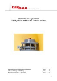
Pressure Relief Devices<br />
for oil filled electric Transformers<br />
Description and general specifications<br />
Operating instructions and maintenance<br />
Finished product quality control tests<br />
page<br />
page<br />
page<br />
02<br />
03<br />
09<br />
1
Description and general specifications.<br />
Aim of the safety valves on electric transformers<br />
The transformer tank filled with cooling liquid is a container subject to internal pressure and then has to be<br />
provided with one or more safety valves suitably calibrated for the maximum allowed pressure, so that<br />
overpressure caused by internal faults can be instantaneously relieved through the valves, thus avoiding<br />
greater damages such as the deformation or even the burst of the tank and the spraying of hot oil with<br />
subsequent fire risks. It is necessary to protect the transformer tank with a suitable equipment capable of<br />
almost instantaneously discharging overpressure already at the development, before the structure integrity is<br />
damaged and the safety valves has just this function.<br />
General features<br />
The safety valves consist schematically of:<br />
a valve base comprising the valve opening venting area with its specially profiled gasket and a seat<br />
for an O-ring gasket on the flanged end towards the transformer’s tank;<br />
a valve cap pressed against the profiled gasket by<br />
calibrated helical spring, thus making the valve completely tight up to the rated pressure;<br />
a splash diverter to avoid damages caused by hot oil sprinkles (on request);<br />
a single or a double electrical contact (on request).<br />
Mechanical protection degree : IP 65<br />
Insulation : 2000V 50Hz between terminals and<br />
earth for a 60 seconds time<br />
Cable gland : PG 13,5<br />
Microswitch breaking capacity :<br />
10 A 250V AC<br />
1 A 125V DC<br />
Safety valves - types<br />
The safety valves are built with different Major Diameters and rated pressure to satisfy the requirements of<br />
the various applications.<br />
TYPE MAJOR DIAMETER RATED PRESSURE PREVAILING USE<br />
T 125 - VS 150 125mm. 0,3 1 bar big power transformers<br />
VS 100 100mm. 0,3 1 bar medium power transformers<br />
T80 - VS 80 80mm. 0,3 1 bar small power transformers<br />
T 50 – VS 50 50mm. 0,3 1 bar cable boxes - small tanks<br />
Safety valves series VS : the advantage of safety valves serie VS consists in the total absence of projecting<br />
parts in the transformers tank making the mounting point choose easier. These valves can be mounted, with<br />
regards to their base plane, both horizontally on the cover and vertically on the transformer walls at the<br />
points where their safety action is presumed to be more necessary.<br />
Safety valves series T : the advantage of safety valves series T is that, showing a good effectiveness and<br />
reliability of valves serie VS, their simplicity consent to obtain very competitive prices.<br />
2
Operating instruction and maintenance.<br />
Instruction for mounting safety valves<br />
The data about the transformer point where a short circuit is most likely to occur, the preferential direction the<br />
resulting shock wave may have, the intensity this one can reach, all depend on the transformer power, its<br />
transformation ratio, its construction characteristic and the behaviour of the other installed protection<br />
equipment.<br />
Therefore, is not possible to give strict rules about safety valves application. It is the manufacturer who must<br />
decide each time and on his own experience the valve type and its position.<br />
It is important to take these general suggestions into due consideration for a correct choice :<br />
<br />
<br />
<br />
the safety valves must be mounted near<br />
the points where a failure is most likely to<br />
occur. When a single valve is mounted<br />
the barycentric position with regards to<br />
these points shall be chosen;<br />
the exhaust rated diameter shall be<br />
connected with the transformer oil<br />
quantity and with the number of mounted<br />
valves;<br />
the presence of gas or air-bubbles under<br />
the valve cap may negatively affect valve<br />
opening speed.<br />
<br />
Therefore, before operating the<br />
transformer, it is important to let possibly<br />
accumulated air come out through the<br />
suitable breather screw and above all to<br />
mount the valve so that the possible gasbubbles<br />
developed during operation can<br />
not accumulate on the valve;<br />
the operating pressure must be definitely<br />
lower than the maximum allowed<br />
pressure in the tank, but higher than<br />
possible pressure peak reached during<br />
operation.<br />
Mounting and maintenance<br />
The safety valves mounting is carried out by means of the suitable fastening holes of the flange, after the<br />
splash diverter removal and after the insertion of the O-ring gasket supplied with the valve.<br />
After the transformer filling, the air developed under the valve must be breathed by unscrewing the suitable<br />
breathing screw. This breathing screw shall be tightened again as soon as the oil starts to come out.<br />
During operation the safety valves do not need a particular maintenance. Nevertheless, it is convenient to<br />
regularly check the electric contact good operation and to verify if there is no gas accumulation.<br />
Instruction for ordering safety valves<br />
The exhaust rated diameter shall be connected with the transformer oil quantity and with the number of<br />
mounted valves. When a single valve is mounted the barycentric position, with regards to the points where a<br />
failure is most likely to occur, must be chosen.<br />
To help the Technical Department to state types and number of valves to be mounted on a transformer, is<br />
possible to study the following indicative table :<br />
VALVE TYPE<br />
T 50<br />
VS 50<br />
T 80<br />
VS 80<br />
VS 100<br />
T 125<br />
VS 150<br />
OIL QUANTITY<br />
up to 1.000 dm 3 (900Kgs.)<br />
up to 1500 dm 3 (1300Kgs.)<br />
up to 4.000 dm 3 (3.600Kgs.)<br />
up to 6.000 dm 3 (5.400Kgs.)<br />
up to 20.000 dm 3 (18.000Kgs.)<br />
up to 20.000 dm 3 (18.000Kgs.)<br />
up to 35.000 dm 3 (31.500Kgs.)<br />
3
In case of tanks containing larger quantities of oil must be mounted 2 or more valves of suitable dimensions<br />
(i.e.: if oil quantity is 95.000dm 3 must be mounted 3 valves type VS 150).<br />
SAFETY VALVES type 50T – 80T – 125 T<br />
4
SAFETY VALVE type VS 50<br />
Safety Valve type VS 50<br />
5
SAFETY VALVE type VS 80<br />
Safety Valve type VS 80<br />
equipped with 1or 2 change-over contacts<br />
6
SAFETY VALVE type VS 100<br />
88.0<br />
100.0 100.0<br />
4<br />
158.0<br />
DN100<br />
Ø114.0<br />
Ø135.0<br />
Ø180.0<br />
18<br />
Ø26.0<br />
100.0<br />
112.0<br />
4<br />
102.5<br />
102.5<br />
25.0<br />
170.0<br />
15.0<br />
Safety Valve type VS 100<br />
equipped with 1 change-over contact<br />
7
SAFETY VALVE type VS150<br />
127.0<br />
4<br />
199.0<br />
DN150<br />
Ø168.0<br />
Ø189.0<br />
Ø240.0<br />
142.5<br />
160.0<br />
Ø 18<br />
Ø26.0<br />
4<br />
285.0<br />
294.0<br />
50.0 190.0<br />
16.<br />
Safety Valve type VS 150<br />
equipped with 1 or 2 change-over contacts<br />
8
Finished product quality control tests.<br />
Hydraulic test for tightness for the body :<br />
the aluminium alloy case is mounted on the wall of a tank filled with oil at the temperature of 90°C and at the<br />
pressure of 300 kpa. After 8 hours no leakages must be observed.<br />
Dimensional check.<br />
General function test :<br />
the safety valve is mounted on a testing pressure circuit at the atmospheric pressure value. The pressure,<br />
controlled by a microprocessor based monitoring unit and recorded by a special recording instrument,<br />
slowly increases up to the Operating Pressure value - 5 kpa. The valve remains at this pressure value for 6<br />
hours. During this period the valve must be completely sealed.<br />
Following three different gradients the pressure increases again to the Operating Pressure value. It’s verified<br />
that the effective pressure of opening of the valve is contained in the following interval : O.P. -5% < O.P. <<br />
O.P. +8%.<br />
Check of contacts actuation : this test is performed by means of visual indicators mounted on a panel<br />
board. Commutation tolerance, commutation differential and electrical circuits are verified.<br />
Check of electrical contact unit mechanical protection degree : IP 65.<br />
Insulation test : carried out by means of a microprocessor controlled testing unit.<br />
I EDITION AUGUST 2006<br />
Terman '90 S.r.l., Via Ghisalba, 13-20/21, 20021 Bollate (MI) – Italy. Tel: +39 02 38 30 37 12, Fax: +39 02 38 30 37 19,<br />
E-Mail info@terman.com, www.terman.com<br />
C.F./P. IVA 09970270154 – C.C.I.A.A. 1332904 – Trib. Milano Reg. Soc. 302729 – Cap. Soc. € 119.000<br />
9