Magnetic Oil Level Gauges for electrical Transformers - TERMAN
Magnetic Oil Level Gauges for electrical Transformers - TERMAN
Magnetic Oil Level Gauges for electrical Transformers - TERMAN

You also want an ePaper? Increase the reach of your titles
YUMPU automatically turns print PDFs into web optimized ePapers that Google loves.
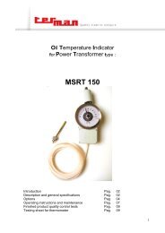
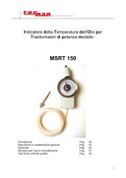
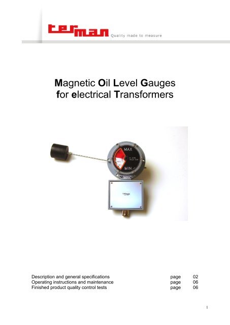
<strong>Magnetic</strong> <strong>Oil</strong> <strong>Level</strong> <strong>Gauges</strong><br />
<strong>for</strong> <strong>electrical</strong> Trans<strong>for</strong>mers<br />
Description and general specifications<br />
Operating instructions and maintenance<br />
Finished product quality control tests<br />
page<br />
page<br />
page<br />
02<br />
06<br />
06<br />
1
Description and general specifications.<br />
The magnetic oil level gauges serve the purpose of visually indicating the oil level in a tank or in a<br />
conservator of oil filled trans<strong>for</strong>mers.<br />
This instrument is composed of a disc indicator (or a red pointer) behind a dial frame and a float linked to<br />
said indicator by means of a magnetic field of <strong>for</strong>ce.<br />
The indicator disc is <strong>for</strong> one half enamelled white and, <strong>for</strong> the other half, red. Alternatively the colour<br />
proportion visible through the dial glass indicates the respective level position, whilst the dial face is marked<br />
at minimum and maximum oil level and at level corresponding to 20°C and 85°C (on demand other markings<br />
are available).<br />
The oil level indicator's float follows the oil level fluctuations thus causing a permanent magnet to be shifted<br />
in turn.<br />
This last is connected, by means of a magnetic field of <strong>for</strong>ce, to another magnet located into the external part<br />
of the oil level indicator casing. The rotation of the internal magnet will cause, on its turn, the rotation of the<br />
external magnet which is integrally fitted to the disc indicator / red pointer. The magnetic joint consents to the<br />
two-colour disc / red pointer to be not immersed in the oil but separated from it by an oil tight partition which<br />
is cast integrally to the instrument's body.<br />
When the conservator oil level is at its minimum there is visible within the dial only the red portion of the<br />
indicator disc, whilst an oil level increase will progressively bring into prominence the white portion of the<br />
indicator disc.<br />
The gauge may be provided with one, two or four microswitches <strong>for</strong> signalling of minimum and/or and<br />
maximum oil level.<br />
Casing : weather proof light metal alloy, stove<br />
enamel finished, suitable <strong>for</strong> outdoor mounting<br />
Protection degree : IP 54.<br />
Microswitches making & breaking capacity :<br />
• 3A 125/250V AC (resistive)<br />
• 0,5A 125V DC <strong>for</strong> inductive load L/R= 40ms<br />
• 0,25A 250V <strong>for</strong> inductive load L/R= 40ms<br />
Insulation test : 2000V 50Hz between terminals<br />
and earth <strong>for</strong> a 60 sec. time.<br />
Working temperature : all the magnetic oil level<br />
gauge are suitable <strong>for</strong> working with:<br />
oil temperature between -25°C / + 120°C<br />
ambient temperature between -25°C /+ 60°C<br />
Float movement : this may be in the radial<br />
direction (type “B”) or in the axial direction (type<br />
“A”)<br />
2
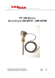
MAGNETIC OIL LEVEL GAUGE L80<br />
MAGNETIC OIL LEVEL GAUGE L100<br />
3
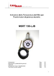
MAGNETIC OIL LEVEL GAUGES type LA140 / 220 / 340<br />
Type L140<br />
30°<br />
Type L 220<br />
L 340<br />
S<br />
22°30'<br />
76<br />
24<br />
53<br />
N.HOLES Ø D2<br />
+85<br />
MAX<br />
OIL LEVEL<br />
O-RING<br />
120°<br />
60<br />
Ø D1<br />
Ø D<br />
CENTRE OF<br />
CONSERVATOR<br />
+20<br />
-20<br />
MIN<br />
LIVELLO OLIO<br />
L<br />
DIAMETER OF<br />
CONSERVATOR<br />
Ø DC<br />
58<br />
VARIABLE LENGHT<br />
Ø 58<br />
PG 16<br />
TYPE ØD s ØD1 O-ring Ø d2 L N. holes Weight R standard<br />
LA140 140 24 125 OR 186(6362) 7 245 6 1,9 kg. max 370mm.<br />
LA220 220 24 190 OR 221 11,5 325 8 2,9 kg. max 550mm.<br />
LA340 340 24 305 OR 248(8100) 18 445 8 6 kg. max 710mm.<br />
4
120°<br />
120°<br />
MAGNETIC OIL LEVEL GAUGES type LB 140 / 220 / 340<br />
Type L140<br />
30°<br />
Type L 220<br />
L 340<br />
22°30'<br />
90<br />
24<br />
53<br />
Type L140<br />
N.HOLES Ø D2<br />
30°<br />
Type L 220<br />
L 340<br />
+85<br />
MAX<br />
OIL LEVEL<br />
22°30'<br />
O-RING<br />
90<br />
24<br />
53<br />
N.HOLES Ø D2<br />
60<br />
Ø D1<br />
Ø D<br />
DIAMETER OF<br />
CONSERVATOR<br />
DIAMETER OF<br />
CONSERVATOR<br />
Ø DC<br />
Ø DC<br />
+20<br />
-20<br />
+85<br />
+20<br />
-20<br />
MAX<br />
MIN<br />
MIN<br />
LIVELLO OLIO<br />
OIL LEVEL<br />
LIVELLO OLIO<br />
VARIABLE LENGHT<br />
58<br />
VARIABLE LENGHT<br />
58<br />
Ø 58<br />
O-RING<br />
60<br />
Ø D1<br />
PG 16<br />
Ø D<br />
L<br />
L<br />
Type ØD s ØD1 O-ring Ø d2 L N. holes WEIGHT R standard<br />
LB140 140 24 125 OR 186(6362) 7 245 6 2,3 kg. max 370mm.<br />
LB220 220 24 190 OR 221 11,5 325 8 3,3 kg. max PG 550mm.<br />
16<br />
LB340 340 24 305 OR 248(8100) 18 445 8 6,3 kg. max 710mm.<br />
Type ØD s ØD1 O-ring Ø d2 L N. holes WEIGHT R standard<br />
LB140 140 24 125 OR 186(6362) 7 245 6 2,3 kg. max 370mm.<br />
LB220 220 24 190 OR 221 11,5 325 8 3,3 kg. max 550mm.<br />
LB340 340 24 305 OR 248(8100) 18 445 8 6,3 kg. max 710mm.<br />
Ø 58<br />
5
Operating instructions and maintenance.<br />
OIL LEVEL INDICATORS type LA - radial float<br />
Must be fitted offset with respect to the horizontal axis of the conservator ( distance "S" in the figure ) in<br />
order to have an exact indication of the minimum and maximum oil level.<br />
To calculate S use the <strong>for</strong>mula :<br />
S=(0,5DC- 40) x 0,577 DC= conservator diameter dimensions =mm.<br />
The length of the float stem = R can be calculateted by using the <strong>for</strong>mula :<br />
R=(0,5DC -10) x 1,15 DC=conservator diameter dimensions =mm.<br />
OIL LEVEL INDICATORS type LB - axial float<br />
Must be mounted exactly in the centre of the conservator and the length of the float stem = R can be<br />
calculateted by using the <strong>for</strong>mula :<br />
R=(0,5DC -10) x 1,15 DC=conservator diameter dimensions =mm.<br />
Maintenance :<br />
On regular basis check the functionality of the device by manually rotating the indicator disc thus verifying<br />
the correct commutation of the contacts. The manual rotation must be made very slowly to avoid<br />
disconnection of the magnetic field !<br />
Being the transparent made of polycarbonate, when cleaning use a soft cloth and soapy water.<br />
Finished product quality control tests.<br />
Hydraulic test <strong>for</strong> tightness <strong>for</strong> the body : the aluminium alloy casing is filled with oil at the temperature of<br />
90°C and at the pressure of 300 kpa.<br />
After 8 hours no leakages must be observed.<br />
The same test is carried out <strong>for</strong> float.<br />
Dimensional check.<br />
Hydraulic test <strong>for</strong> tightness of the finished gauge : the test is carried out by mounting the oil level gauge<br />
on a tank filled with oil at the temperature of 90°C and at the pressure of 200 kpa. Said test lasts 4 hours.<br />
During this period no oil leakage is admitted.<br />
Manual and hydraulic inspection of the electric contacts actuation : this test is carried out both on<br />
minimum and maximum levels circuits.<br />
It’s per<strong>for</strong>med by means of visual indicators mounted on a panel-board.<br />
Check of instrument mechanical protection degree : IP 55.<br />
Isolation test : carried out by means of a microprocessor controlled testing unit.<br />
I EDITION AUGUST 2006<br />
Terman '90 S.r.l., Via Ghisalba, 13-20/21, 20021 Bollate (MI) – Italy. Tel: +39 02 38 30 37 12, Fax: +39 02 38 30 37 19,<br />
E-Mail info@terman.com, www.terman.com<br />
C.F./P. IVA IT 09970270154 – C.C.I.A.A. 1332904 – Trib. Milano Reg. Soc. 302729 – Cap. Soc. € 119.000<br />
6