Computational engineering for wind-exposed thin-walled structures
Computational engineering for wind-exposed thin-walled structures
Computational engineering for wind-exposed thin-walled structures

You also want an ePaper? Increase the reach of your titles
YUMPU automatically turns print PDFs into web optimized ePapers that Google loves.
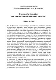
<strong>Computational</strong> <strong>engineering</strong> <strong>for</strong> <strong>wind</strong>-<strong>exposed</strong> <strong>thin</strong>-<strong>walled</strong> <strong>structures</strong> 5<br />
250<br />
CFD<br />
18 nodes,<br />
10 elements<br />
CSD<br />
15 nodes,<br />
8 elements<br />
Fig. 5. Discretization of the interface<br />
displacement upper boundary [mm]<br />
200<br />
150<br />
100<br />
50<br />
0<br />
−50<br />
−100<br />
−150<br />
t 1 = 0:025 s<br />
t 2 = 0:0125 s<br />
t 3 = 0:00625 s<br />
−200<br />
0 0.5 1 1.5 2 2.5 3 3.5<br />
time [s]<br />
Fig. 6. Displacement <strong>for</strong> dierent t<br />
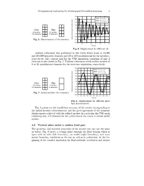
uni<strong>for</strong>m renement was per<strong>for</strong>med in two levels which leads to 13,200<br />
and 105,600 hexaeder elements and 40 or 160 quadrilaterals <strong>for</strong> the interface,<br />
respectively. The coarsest grid <strong>for</strong> the CSD simulation consisting of only 2<br />
elements is also shown in Fig. 7. Uni<strong>for</strong>m renement yields surface meshes of<br />
8 or 32 quadrilateral elements <strong>for</strong> the structure simulation, respectively.<br />
CFD<br />
18 nodes,<br />
10 elements<br />
CSD<br />
6nodes,<br />
2 elements<br />
Fig. 7. Initial interface discretization<br />
displacement upper boundary [mm]<br />
300<br />
250<br />
200<br />
150<br />
100<br />
50<br />
0<br />
−50<br />
−100<br />
−150<br />
CFD10=CSD 2<br />
CFD40=CSD 8<br />
CFD160=CSD 32<br />
−200<br />
0 0.1 0.2 0.3 0.4 0.5 0.6 0.7 0.8 0.9 1<br />
time [s]<br />
Fig. 8. Displacement <strong>for</strong> dierent interface<br />
discretizations<br />
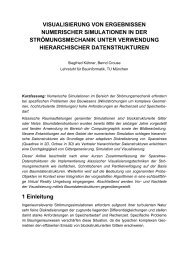
Fig.8points out the insucient accuracy of the results corresponding to<br />
the initial interface discretizations and the good agreement of the transient<br />
displacements achieved with the rened meshes. In particular the CSD mesh<br />
consisting only of 2 elements <strong>for</strong> the y-direction is too coarse to obtain useful<br />
results.<br />
4.2 Vertical plate under a sudden <strong>wind</strong> gust<br />
The geometry and material properties of the second test case are the same<br />
as be<strong>for</strong>e. Fig. 9 shows a cutting plane through the uid domain which is<br />
open with an inlet (left boundary), an outlet (right boundary), and symmetric<br />
boundary conditions at the top as well as in z-direction. At the beginning<br />
of the coupled simulation the uid suddenly accelerates and adopts