Series 5000 IOM - Eastech Flow Controls
Series 5000 IOM - Eastech Flow Controls
Series 5000 IOM - Eastech Flow Controls

You also want an ePaper? Increase the reach of your titles
YUMPU automatically turns print PDFs into web optimized ePapers that Google loves.
SCOPE OF MANUAL<br />
This manual contains information concerning the<br />
installation, operation and maintenance of the <strong>Series</strong> <strong>5000</strong><br />
Compu-Sonic ultrasonic flowmeter. To ensure proper<br />
performance of the meter, the instructions given in this<br />
manual should be thoroughly understood and followed.<br />
Keep the manual in a readily accessible location for<br />
future reference.<br />
Changes and additions to the original edition of this<br />
manual will be covered by a "CHANGE NOTICE"<br />
supplied with the manual. The change notice will explain<br />
any changes made to the product described in this<br />
manual.<br />
MODEL <strong>5000</strong> TABLE OF CONTENTS<br />
Page<br />
Page<br />
Unpacking and Inspection .................................... 1 Velocity Section.................................................. 17<br />
General Specifications.......................................... 2 Doppler/Pressure Section.................................... 18<br />
INSTALLATION PROCEDURE Calibration Procedures ........................................... 18<br />
Electronics Level Section ...................................................... 19<br />
Enclosure Mounting........................................ 3 Transit Time Velocity Section............................ 22<br />
Wiring Connections ........................................ 4 Integrator Section................................................ 25<br />
Sensors.................................................................. 9 Doppler/Pressure Section.................................... 30<br />
OPERATION Pressure 4-20 Output Adjust............................... 33<br />
Principles of Operation......................................... 11 Doppler 4-20 Output Adjust ............................... 34<br />
Operating Instructions .......................................... 14 Pressure Calibrations .......................................... 35<br />
Normal Operating Procedures .............................. 14 Troubleshooting ..................................................... 39<br />
Integrator Section............................................ 15 Parts List................................................................. 48<br />
Level Section................................................... 15<br />
UNPACKING &<br />
INSPECTION<br />
To avoid damage in transit, <strong>Eastech</strong> Badger products<br />
are shipped to the customer in special shipping<br />
containers. Upon receipt of the product, perform the<br />
following unpacking and inspection procedures:<br />
NOTE: If damage to the shipping container is evident<br />
upon receipt, request the carrier to be present when the<br />
product is unpacked.<br />
a. Carefully open the shipping container following<br />
any instructions that may be marked on the box. Remove<br />
all cushioning material surrounding the product and<br />
carefully lift the product from the container.<br />
Retain the container and all packing material for possible<br />
use in reshipment or storage.<br />
b. Visually inspect the product and applicable<br />
accessories for any physical damage such as scratches,<br />
loose or broken parts, or any other sign of damage that<br />
may have occurred during shipment.<br />
NOTE: If damage is found, request an inspection by<br />
the carrier's agent within 48 hours of delivery and file a<br />
claim with the carrier. A claim for equipment damage in<br />
transit is the sole responsibility of the customer.<br />
1<br />
11/01<br />
941131
GENERAL DESCRIPTION<br />
The <strong>Series</strong> <strong>5000</strong> Compu-Sonic flowmeters are<br />
designed to measure flow in open channels or partially<br />
filled conduits. These flowmeters utilize ultrasonic<br />
measurement techniques to determine fluid velocity and<br />
fluid depth to calculate the volume of flow.<br />
There are several installation configurations utilized in<br />
the <strong>Series</strong> <strong>5000</strong> flowmeters depending on the particular<br />
application. These installation configurations are divided<br />
into two models: the Model 5100 where the velocity and<br />
level sensors are mounted on existing open channels or<br />
pipes; and the Model 5200 where the velocity and level<br />
sensors are factory mounted on a fabricated spool that is<br />
installed into a section of the pipe line.<br />
The <strong>Series</strong> <strong>5000</strong> flowmeters are calibrated at the<br />
factory to the application parameters provided by the<br />
customer. Minimal on-site calibration of the system is<br />
usually required. Factory start-up is provided with each<br />
flowmeter to ensure proper operation of the system and to<br />
train personnel that will be responsible for maintaining<br />
the flowmeter.<br />
At the front of this manual are the data sheets and an<br />
installation drawing describing the parameters for which<br />
the flowmeter was calibrated and the installation<br />
configuration for the velocity and level sensors. The<br />
customer should view these for correctness and notify the<br />
factory should he discover any parameters that are not<br />
correct.<br />
The following sections of this manual cover the<br />
installation and operation procedures for the <strong>Series</strong> <strong>5000</strong><br />
flowmeters. These procedures should be read before<br />
attempting installation or operation of the flowmeter.<br />
The Installation Section for the velocity and level<br />
sensors will cover the various installation configurations.<br />
Refer to the data sheet and installation drawing in the<br />
front of this manual for the proper installation procedure<br />
to be used.<br />
Below are the General Specifications for the <strong>Series</strong><br />
<strong>5000</strong> flowmeters.<br />
GENERAL SPECIFICATIONS<br />
OUTPUT SIGNALS<br />
DISPLAYS<br />
POWER<br />
ENCLOSURE<br />
TEMPERATURE<br />
LIMITS<br />
Isolated 4-20 mADC for flow, 800 ohms max.<br />
Isolated 4-20 mADC for level, 800 ohms max.<br />
Isolated 4-20 mADC for velocity, 800 ohms max.<br />
Pulse output to pace sampler, Triac max 230 VAC at 600 mA<br />
Pulse output for remote totalizer, open collector 40 VDC max. at 100 mA<br />
Four assignable relay outputs, SPDT, 1 amp at 120 volts.<br />
Four 2 line, 24 character LCD, for flow, level, velocity and Doppler/pressure<br />
117 VAC 20 watts (210 watts with heater and thermostat)<br />
NEMA 4X with viewing window<br />
Sensors: -20° F to 160° F (-30° C to 70° C)<br />
Electronics: 32°F to 150°F (0°C to 65°C), -40°F to 150°F (-40°C to 65°C)<br />
with heater and thermostat<br />
2
INSTALLATION<br />
ELECTRONIC ENCLOSURE<br />
The <strong>Series</strong> <strong>5000</strong> electronics is housed in a NEMA 4X<br />
plastic enclosure designed for wall mounting. The<br />
enclosure is normally provided with heater and<br />
thermostat, front door viewing window and lockable door<br />
latches. The front door can be provided without the<br />
viewing window at the option of the user.<br />
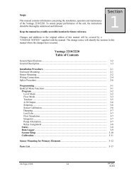
ENCLOSURE MOUNTING<br />
Figure 1 shows the dimensions of the enclosure. If the<br />
enclosure is to be installed outdoors, care should be<br />
taken so it is not exposed to the direct sun light by<br />
selecting an area in the shade or providing a sun<br />
shield.<br />
The enclosure is provided with four mounting ears<br />
which are packed in a plastic bag and taped to the inside<br />
of the enclosure. This bag will also contain the screws for<br />
installing the ears to the enclosure and the keys for the<br />
lockable door latch.<br />
The enclosure weights approximately 40 pounds, and<br />
care should be taken to securely mount the enclosure to<br />
the wall.<br />
12.87 "<br />
1.44 "<br />
7.87 "<br />
24.5 "<br />
23.62 "<br />
0.335 " Dia.<br />
15.75 "<br />
FIGURE 1<br />
3
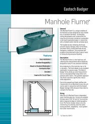
WIRING CONNECTIONS<br />
The <strong>Series</strong> <strong>5000</strong> enclosure is provided with five (5)<br />
holes in the bottom of the housing for 1/2 inch conduit<br />
connections. These five (5) holes allow the entry of the<br />
Doppler/pressure cable, AC power wires, transit-time<br />
velocity sensor cables, ultrasonic level sensor cable, and<br />
4-20 mADC signal output wires.<br />
Terminal blocks for connecting the AC power wires,<br />
signal output wires, transit time velocity sensor cables<br />
and ultrasonic level sensor cable are mounted on the back<br />
panel inside the enclosure. The Doppler/pressure sensor<br />
cable connects to a terminal block on the<br />
Doppler/pressure circuit board on the back panel. To gain<br />
access to the wiring terminals, open the front door, lift the<br />
two (2) latches on the front panel and swing out the front<br />
panel. Refer to Figures 2 and 3.<br />
connection. Terminal 3 is the earth ground (green wire)<br />
connection.<br />
Front<br />
Panel<br />
Front<br />
Panel<br />
Latches<br />
Wiring connections should be made by a licensed<br />
electrician following the electrical wiring codes for your<br />
area.<br />
AC POWER CONNECTIONS. The AC power wires are<br />
connected to terminal 1, 2, and 3 of the Panel Terminal<br />
Block. Terminal 1 is the high, or hot, (black wire)<br />
connection. Terminal 2 is the low or neutral (white wire)<br />
FIGURE 2<br />
FRONT OF ENCLOSURE<br />
WITH DOOR OPEN<br />
WDL-1<br />
Doppler/Pressure<br />
PCB<br />
128 DCM<br />
Logger<br />
UF<br />
UH<br />
FIGURE 3<br />
VIEW OF BACK PANEL<br />
4
FIGURE 4<br />
BACK PANEL TERMINAL<br />
BLOCK WIRING CONNECTIONS<br />
AC POWER-LINE (FUSED)<br />
AC POWER-NEUTRAL<br />
AC POWER-GROUND<br />
OPEN<br />
OPEN<br />
LEVEL/RELAY 1 -NC<br />
LEVEL/RELAY 1 -C<br />
LEVEL/RELAY 1 -NO<br />
LEVEL/RELAY 2 -NC<br />
LEVEL/RELAY 2 -C<br />
LEVEL/RELAY 2 -NO<br />
SAMPLER<br />
-LO<br />
SAMPLER<br />
-HI<br />
REMOTE TOTALIZER (- )<br />
REMOTE TOTALIZER (+)<br />
NOT USED<br />
NOT USED<br />
HI SCALE FLOW (4-20) (- )<br />
HI SCALE FLOW (4-20) (+)<br />
LO SCALE FLOW (4-20) (- )<br />
LO SCALE FLOW (4-20) (+)<br />
VELOCITY (4-20) (- )<br />
VELOCITY (4-20) (+)<br />
LEVEL (4-20) (- )<br />
LEVEL (4-20) (+)<br />
VEL / RELAY 3 -NC<br />
VEL / RELAY 3 -C<br />
VEL / RELAY 3 -NO<br />
VEL / RELAY 4 -NC<br />
VEL / RELAY 4 -C<br />
VEL / RELAY 4 -NO<br />
LEVEL COMM VTX<br />
LEVEL COMM GND<br />
LEVEL COMM RX<br />
LEVEL COMM TX<br />
OPEN<br />
# 1<br />
# 2<br />
# 3<br />
# 4<br />
# 5<br />
# 6<br />
# 7<br />
# 8<br />
# 9<br />
#10<br />
#11<br />
#12<br />
#13<br />
#14<br />
#15<br />
#16<br />
#17<br />
#18<br />
#19<br />
#20<br />
#21<br />
#22<br />
#23<br />
#24<br />
#25<br />
#26<br />
#27<br />
#28<br />
#29<br />
#30<br />
#31<br />
#32<br />
#33<br />
#34<br />
#35<br />
#36<br />
1<br />
FUSE .2A 250V HEATER<br />
FUSE .5A 250V<br />
36<br />
LOW LEVEL ALARM. Terminals 6, 7 and 8 are the<br />
connections for the low level alarm relay. The relay is a<br />
dry contact single pole double through (SPDT) with a 1<br />
amp max contact rating. Terminal 6 is the normally<br />
closed side of the relay, Terminal 7 is common, and<br />
Terminal 8 is the normally open side. This alarm is<br />
adjusted by the Level Monitor control panel of the<br />
electronics. Refer to the Operating Instructions Section of<br />
this manual for the procedure.<br />
HI LEVEL ALARM. Terminals 9, 10, and 11 are the<br />
connections for the high level alarm relay. The relay is a<br />
dry contact single pole double throw (SPDT) with a 1<br />
amp max contact rating. Terminal 9 is the normally<br />
closed side of the relay, Terminal 10 is the common, and<br />
Terminal 11 is the normally open side. This alarm is<br />
adjusted by the Level Monitor control panel of the<br />
electronics. Refer to the Operating Instructions Section of<br />
this manual for the procedure.<br />
5
SAMPLER OUTPUT. Terminals 12 and 13 are the<br />
connections for the sampler output. This output is a<br />
TRIAC switch with a rating of 230 VAC at 600 mA max.<br />
Terminal 12 is the LO or negative connection and<br />
Terminal 13 is the HI or positive connection. The setting<br />
of the sampler rate is made on the main <strong>5000</strong> control<br />
panel of the electronics. Refer to the Operating<br />
Instructions Section of this manual for the procedure.<br />
REMOTE TOTALIZER. Terminals 14 and 15 are the<br />
connections for the remote totalizer output. This output is<br />
an open collector transistor output rated at 50 volts DC<br />
maximum at 100 mA.<br />
HI SCALE FLOW OUTPUT. This output is only available<br />
when operating the meter in dual range. Terminals 18 and 19<br />
are the connections for the High Scale <strong>Flow</strong> output.<br />
Terminal 18 is the negative (-) connection and Terminal<br />
19 is the positive (+) connection. These are the<br />
connections for the dual range 4-20 mADC flow output<br />
signal (0 to 100% full scale). For adjustment of this<br />
signal, refer to the Operating Instructions Section of this<br />
manual. If your meter has been setup for a dual flow<br />
range (refer to the data sheet in the front of this manual),<br />
the Lo Scale output connections could be used.<br />
LO SCALE FLOW OUTPUT. Terminals 20 and 21 are<br />
the connections for the Lo Scale <strong>Flow</strong> output. Terminal<br />
20 is the negative (-) connection and Terminal 21 is the<br />
positive (+) connection. These are the normal<br />
connections for the single range 4-20 mADC flow<br />
output signal (0-100% full scale). In the dual range they<br />
are<br />
the<br />
4-20 mADC output (0 to crossover flow value). For<br />
example, if your meter was scaled for a maximum flow of<br />
20 MGD and crossover flow is 2 MGD, the Lo Scale<br />
<strong>Flow</strong> 4-20 mADC signal will represent 0 to 2 MGD. For<br />
adjustment of this signal, refer to the Operating<br />
Instructions Section of this manual.<br />
VELOCITY OUTPUT. Terminals 22 and 23 are the<br />
connections for the velocity output signal. Terminal 22 is<br />
the negative (-) connection and Terminal 23 is the<br />
positive (+) connection. This is a 4-20 mADC signal that<br />
represents 0 to 100% of the full scale velocity for which<br />
the meter has been setup. Refer to the data sheet at the<br />
front of this manual for the full scale velocity.<br />
LEVEL OUTPUT. Terminals 24 and 25 are the<br />
connections for the level output signal. Terminal 24 is the<br />
negative (-) connection and Terminal 25 is the positive<br />
(+) connection. This is a 4-20 mADC signal that<br />
represents 0 to 100% of the maximum level for which the<br />
meter has been setup. Refer to the data sheet at the front<br />
of this manual for the maximum level.<br />
6
SERIES <strong>5000</strong> DOPPLER/PRESSURE BOARD CUSTOMER WIRING/OPERATION<br />
The <strong>Series</strong> <strong>5000</strong> Compound Ultrasonic flowmeter has<br />
been designed to be versatile as each customer application<br />
is unique and special. With the additional of the WDL-1<br />
Doppler/pressure board and the 128 DCM<br />
Logger board, the <strong>Series</strong> <strong>5000</strong> becomes not only a<br />
velocity and level unit to achieve the equation Q = V x A,<br />
but has redundant backup of velocity and level<br />
measurements utilizing different techniques to assure<br />
continuous operation in almost all conditions.<br />
<strong>5000</strong><br />
Electronic<br />
Case<br />
VAC<br />
Power***<br />
Dopper-(Velocity)<br />
Pressure-(Level)<br />
LCD Display<br />
4-20madc***<br />
Output<br />
5 button setup<br />
Logger Input***<br />
Modem Port<br />
DB-9 Male<br />
Doppler/Pressure<br />
Sensor Connection<br />
WDL-1<br />
Doppler/Pressure<br />
PCB<br />
Optional<br />
128 DCM<br />
Logger<br />
Computer Port<br />
DB-9 Female<br />
(See manual 941281<br />
for operation)<br />
Communications<br />
Port<br />
Customer Wiring<br />
Terminal Strip<br />
Aneriod Bellows<br />
For Pressure<br />
Sensor Vent Tube<br />
UF<br />
UH<br />
***Factory wired and terminated<br />
Transit Time Velocity<br />
Sensor Connection<br />
Ultrasonic Height<br />
Sensor Connection<br />
FIGURE 5<br />
Figure 5 will give you an overall view of the back<br />
panel of the <strong>Series</strong> <strong>5000</strong> enclosure, please note the<br />
locations of the WDL-1 and the 128 DCM Logger board.<br />
These boards, if supplied as options will be completely<br />
wired<br />
for operation at the factory. The only terminations<br />
necessary will be the WDL-1 Doppler/pressure sensor,<br />
pressure vent tube, and the optional modem or computer<br />
interface cables if included.<br />
7
WDL-1 Sensor Wiring Diagram<br />
117VAC Input<br />
GLH<br />
2 line, 24 character<br />
LCD display<br />
4-20madc output<br />
4<br />
(-)<br />
321<br />
(+)<br />
(-)<br />
(+)<br />
Pressure/Level<br />
Doppler/Velocity<br />
VEL<br />
LEVEL<br />
00.00 FPS<br />
000.0 IN<br />
UP<br />
DOWN<br />
RIGHT<br />
SELECT<br />
UP Button= Scroll up<br />
Down Button= Scroll down<br />
Right Button= Move cursor right<br />
Select Button= Move to next screen<br />
WDL-1 SENSOR TB-1<br />
1-CENTER<br />
2-SHIELD W/EXTRA GND<br />
3-CENTER<br />
4-SHIELD<br />
5-BLACK<br />
6-RED<br />
7-GREEN<br />
8-WHITE<br />
WDL-1<br />
Doppler/Pressure<br />
PCB<br />
TB1<br />
1234 567 8<br />
MENU<br />
Menu Button= Enter or escape program<br />
Communication<br />
(To set up zero/span for<br />
WDL-1 sensor and to<br />
communicate with board)<br />
ANERIOD<br />
BELLOWS<br />
WDL-1 Sensor and Cable<br />
Figure 6<br />
2<br />
8
BACK PANEL DOPPLER/PRESSURE UNIT<br />
A partial view of the back panel of the Model <strong>5000</strong> enclosure showing the Doppler/pressure circuit board.<br />
DOPPLER/PRESSURE SENSOR CONNECTION<br />
The velocity/pressure sensor cable consists of two small<br />
black coaxial wires, 5 colored wires and a plastic vent<br />
tube. The sensor cable terminations are made on terminal<br />
block TB2 on the velocity/pressure circuit board. TB2 is<br />
located on the lower left corner of the circuit board.<br />
Any excess length of sensor cable can be cut off, but be<br />
sure to leave enough for proper connections.<br />
Remove five inches of the outside red jacket being<br />
careful not to cut into the wires inside. Carefully strip<br />
away one inch of the outside black insulation jacket from<br />
each of the two coaxial cables. Then strip 1/4" of the<br />
insulation from each of the two coaxial inner conductors.<br />
Strip 1/4" of insulation from each of the five colored<br />
wires.<br />
Inspect the two coaxial cables. Each of them has an<br />
inner conductor and an outside shield wire. One of the<br />
cables also has a bare wire with the shield. Connect the<br />
inner conductor of the coaxial cable without the bare wire<br />
to terminal 1 of TB2. Connect the shield to terminal 2.<br />
Connect the inner conductor of the coaxial cable with the<br />
bare wire to terminal 3 of TB2. Connect the shield and<br />
bare wire to terminal 4. Connect the black wire to terminal<br />
5, red wire to terminal 6, green wire to terminal 7, and the<br />
white wire to terminal 8. Connect the orange wire to<br />
the crimp connector connected to the grounding screw<br />
on the lower left corner of the circuit board.<br />
Insert the vent tube connector from the aneroid<br />
bellows into the vent tube in the red sensor cable.<br />
Use the plastic tie down strap on the back panel<br />
located under the sensor terminal strip to tie the sensor<br />
cable down.<br />
9
VELOCITY AND LEVEL SENSOR CABLES. The<br />
velocity and level sensor cables are connected to terminal<br />
blocks separate from the main back panel terminal block.<br />
They are located below and to the left for the velocity and<br />
below and to the right for the level of the main terminal<br />
block on the back panel (See Figure 3).<br />
Before pulling the sensor cables through the conduit,<br />
mark the ends of the cables to indicate which is the<br />
upstream and downstream sensor cable. Leave<br />
approximately 1 foot of cable extending from the conduit<br />
in the enclosure. Refer to Figure 7 and prepare the cable<br />
ends in the following manner.<br />
cable, making sure not to cut into the center conductor<br />
and remove the inner cover.<br />
VELOCITY SENSOR CABLE CONNECTIONS<br />
After the ends of the cables have been prepared,<br />
loosen the screws on the terminals and remove the two<br />
pairs of clamps on the velocity sensor cable terminal<br />
board.<br />
VELOCITY CABLE TERMINAL BOARD<br />
1. Remove outer cable cover. Measure 1-7/8" from<br />
the end of the cable. With a cutting tool, carefully cut<br />
through the outer covering completely around the cable<br />
making sure not to cut into the outer shield. Make another<br />
cut from the first cut to the end of the cable and remove<br />
the outer cover.<br />
2. Remove outer shield. Measure 1-3/8" from the end<br />
of the cable. With a pair of small side cutters, cut the<br />
shield around the cable at the measured point and remove<br />
the cut off shield.<br />
3. Remove middle cover. Measure 1-1/8" from the<br />
end of the cable. With a cutting tool, carefully cut through<br />
the middle covering completely around the cable making<br />
sure not to cut into the middle shield. Make another cut<br />
from the first cut to the end of the cable and remove the<br />
middle cover.<br />
4. Remove middle shield. Measure 3/4" from the end<br />
of the cable. With a pair of small side cutters, cut the<br />
shield around the cable at the measured point and remove<br />
the cut off shield.<br />
5. Remove inner cover. Measure 1/2" from the end of<br />
the cable. With a cutting tool or pair of wire strippers,<br />
carefully cut the inner covering completely around the<br />
Upstream<br />
Sensor<br />
FIGURE 8<br />
Downstream<br />
Sensor<br />
Take the upstream cable and insert the center<br />
conductor into the upstream terminal connection and<br />
tighten the screw. Slightly pull on the cable to insure the<br />
wire is secured to the terminal. Take the downstream<br />
cable and insert the center conductor into the downstream<br />
terminal connection and tighten the screw. Slightly pull<br />
on the cable to insure the wire is secured to the terminal.<br />
Place the two pairs of clamps over the middle and<br />
outer shields and secure them into place. Verify that the<br />
clamps are making good contact with the shields and that<br />
no wires of the shields are extending beyond their own<br />
clamp down area.<br />
1-7/8"<br />
1-3/8"<br />
1-1/8"<br />
3/4"<br />
1/2" 1/2"<br />
1/4"<br />
3/8"<br />
1/4"<br />
1/2"<br />
Remove<br />
outer<br />
cover<br />
Remove Remove Remove Remove Completed<br />
outer middle middle inner cable<br />
shield cover<br />
1 2<br />
3 sheild 4 cover 5 6<br />
FIGURE 7<br />
VELOCITY AND LEVEL SENSOR<br />
CABLE PREPARATION<br />
10
LEVEL SENSOR CABLE CONNECTION<br />
After the end of the cable has been prepared for the<br />
level sensor, loosen the screws on the terminals on the<br />
level sensor terminal at the lower middle in the enclosure<br />
and remove the two clamps.<br />
LEVEL CABLE TERMINAL BOARD<br />
Factory<br />
Connection<br />
FIGURE 9<br />
Customer<br />
Connection<br />
Take the level sensor cable and insert the center<br />
conductor into the sensor connection and tighten the<br />
screw. Slightly pull on the cable to insure the wire is<br />
secured to the terminal.<br />
Place the clamps over the middle and outer shields and<br />
secure them into place. Verify that the clamps are making<br />
good contact with the shields and that no wires of the<br />
shields are extending beyond their own clamp down area.<br />
This completes the wiring instructions for the <strong>Series</strong><br />
<strong>5000</strong> flowmeter.<br />
LEVEL AND VELOCITY SENSOR MOUNTING<br />
There are several mounting configurations for the<br />
level and velocity sensors depending on the particular<br />
application. Drawings are provided in the front of this<br />
manual detailing the mounting instructions for your<br />
specific application. It is important the dimensions given<br />
on the drawings be held to within the tolerances to insure<br />
the accuracy of the flowmeter.<br />
The Model 5200 is provided with a fabricated spool<br />
piece with the level and velocity sensors factory mounted.<br />
A drawing will be provided in the front of this manual<br />
detailing the proper positioning of the spool piece.<br />
The level sensor cable, doppler/pressure sensor cables, and<br />
the velocity sensor cables should be run in separate metallic<br />
conduit.<br />
This completes the mounting instructions for the level<br />
and velocity sensors.<br />
11
PRINCIPLES OF OPERATION<br />
OPERATION<br />
The <strong>Series</strong> <strong>5000</strong> Compu-Sonic flowmeters utilize a<br />
compound measurement system to compute the flow<br />
through open channel or partially filled conduits.<br />
Transit-time ultrasonic measurement is used to<br />
measure the velocity of the fluid in the flow stream and<br />
ultrasonic level measurement is used to measure the depth<br />
of the fluid. The volume of the fluid flow can be<br />
computed using the Continuity equation which states:<br />
where:<br />
v<br />
A<br />
Q = v x A<br />
Q = <strong>Flow</strong> in Cubic Fee/Second<br />
= Average Velocity in Feet/Second<br />
= Area in Square Feet<br />
Height Sensor<br />
The electronics of the <strong>Series</strong> <strong>5000</strong> flowmeters are<br />
made up of four sections: velocity measurement,<br />
ultrasonic level measurement, Doppler velocity/pressure<br />
level and integrator (H x V).<br />
VELOCITY MEASUREMENT SECTION<br />
The velocity section has its own microprocessor with<br />
EEPROM for non-volatile memory storage of the velocity<br />
meter constants. It has a 2 line, 24 character LCD display<br />
that shows the fluid velocity and operational status of the<br />
velocity electronics. There is a front panel keypad that<br />
allows the user to enter into a menu driven prompt mode<br />
for modifying various parameters and adjusting the 4-20<br />
mA output. This will be described in more detail later in<br />
this section.<br />
The transit time velocity measurement section<br />
transmits acoustic energy pulses between the two velocity<br />
sensors. The velocity sensors are mounted on opposite<br />
sides of the channel or pipe with a separation of<br />
approximately 20°. Each sensor functions as a transmitter<br />
and a receiver.<br />
FLOW<br />
Upstream<br />
Sensor<br />
T2-1 T1-2<br />
Compund<br />
Measurement<br />
Depth Only<br />
Measurement<br />
Velocity<br />
Sensors<br />
FIGURE 10<br />
MAX LEVEL<br />
25%<br />
33%<br />
The two velocity sensors are normally installed at 25%<br />
of the maximum level from the bottom of the channel or<br />
conduit. At this location the velocity measurement will be<br />
within 2 to 4% of the true average velocity of the fluid at<br />
all levels of flow sources. Compound measurement is<br />
accomplished from flow levels of 33% to 100%. For<br />
flows where the fluid depth is less than 33% the level<br />
measurement is used to determine volume flow. In this<br />
mode of measurement a free flow equation, such as<br />
Manning's, is used or if greater accuracy is required, a<br />
flume may be used. An optional Doppler velocity sensor<br />
may be used as a back up for the transit time velocity<br />
sensors. Refer to the installation drawings for proper<br />
location.<br />
12<br />
Downstream<br />
Sensor<br />
FIGURE 11<br />
When there is no flow in the channel or pipe the time<br />
between transmission and reception from e upstream<br />
sensor to the downstream sensor (T1-2) will equal the<br />
transit time between the transmission and reception from<br />
the downstream sensor to the upstream sensor (T2-1).<br />
When there is flow T1-2 will decrease because the<br />
transmitted acoustic energy is aided by the flow and T2-1<br />
will increase because the transmitted acoustic energy is<br />
opposed by the flow. This difference in transit time (T2-1<br />
— T1-2) is directly proportional to the velocity of the<br />
fluid. A 4-20 mADC signal is developed which represents<br />
0 to 100% of the full scale velocity. This signal is sent to<br />
the integrator section.<br />
With the separate Doppler sensor, the Doppler signal<br />
is used when there is a loss of the transmit time signal.<br />
This is automatically switched by the transit time velocity<br />
unit. When the Doppler signal is used, the velocity<br />
display will show NS in the upper right corner.
The Doppler/pressure sensor is normally installed<br />
near, or on, the bottom of the channel or conduit. Fluid<br />
velocity<br />
13
is measured by the Doppler technique. Operating with<br />
twin piezoelectric crystals, 1 mhz ultrasonic energy bursts<br />
are transmitted by the transmitting crystal into the flow<br />
stream at a 30 degree angle. The signals reflect off of<br />
solids, air bubbles, or flow disturbances moving in the<br />
flowstream. The reflected signals are received by the<br />
receiving crystal and sent to the electronics. The<br />
transmitted frequency is shifted or changes frequency<br />
when the signal bounces off of a particle moving in the<br />
flow. The frequency shift is measured to determine the<br />
velocity of the fluid.<br />
Transit Time-Doppler Velocity Switch<br />
The 4-20 mA outputs from both the transit time<br />
velocity unit and the Doppler velocity unit are connected<br />
to the normally open and normally closed contacts of<br />
relays 1 & 2 in the transit time electronics. The common<br />
of the relays is routed to the integrator unit. The relays are<br />
assigned to "LOS" for loss of signal. With transit time<br />
operation, the 4-20 mA output of the transit time unit is<br />
sent to the integrator via the normally closed to common<br />
relay contacts. With a loss of transit time signal, the<br />
relays energize and the 4-20 mA output from the Doppler<br />
is coupled through the normally open contacts to the<br />
common and sent to the integrator unit.<br />
When the transit time signal is restored, the relays are<br />
deactivated and the transit time 4-20 mA output is once<br />
again sent to the integrator unit.<br />
LEVEL MEASUREMENT SECTION<br />
The level section has its own microprocessor with<br />
EEPROM for non-volatile memory storage of the meter<br />
constants. It has a 2-line, 24-character LCD display that<br />
shows the fluid level and operational status of the<br />
electronics. There is a front panel keypad that allows the<br />
user to enter into a menu driven prompt mode for<br />
modifying various parameters and adjusting the 4-20 mA<br />
output. This will be described in more detail later in this<br />
section.<br />
The level section transmits bursts<br />
of acoustic energy from the level<br />
sensor. The acoustic energy is<br />
directed towards the surface of the<br />
fluid. The energy is reflected off the<br />
surface of the water and received<br />
back at the level sensor.<br />
Level Sensor<br />
The time from transmission to<br />
reception of the reflected energy is<br />
measured by the electronics. This time is divided by two<br />
and multiplied by the sonic velocity of the air to compute<br />
the distance from the face of the sensor to the surface of<br />
the fluid. The air temperature is measured to compensate<br />
for changes in the sonic velocity of the air. The depth of<br />
the fluid is then computed based on the parameter<br />
programmed in the electronics pertaining to the mounting<br />
of the level sensor. A 4-20 mADC signal is developed<br />
which represents 0 to 100% of the maximum depth of the<br />
fluid. This signal is sent to the integrator section.<br />
The doppler/pressure sensor contains a pressure cell<br />
for measuring level by pressure. Level is measured by the<br />
direct immersion of the pressure cell (sensor). The<br />
pressure cell can measure level within 0.25% of full scale<br />
over a range from 0.5" to 100".<br />
Ultrasonic Level-Pressure Level Switch<br />
The 4-20 mA outputs from both the ultrasonic level<br />
unit and pressure velocity unit are connected to the<br />
normally open and normally closed contacts of relays 3 &<br />
4 in the level unit electronics. The common of the relays<br />
is routed to the integrator unit. The relays are assigned to<br />
"LOS" for loss of signal. With ultrasonic level operation,<br />
the 4-20 mA output of the level unit is sent to the<br />
integrator via the normally closed to common relay<br />
contacts. With a loss of ultrasonic level signal, the relays<br />
energize and the 4-20 mA output from the pressure unit is<br />
coupled through the normally open contacts to the<br />
common and sent to the integrator unit.<br />
When ultrasonic level signal is restored, the relays are<br />
deactivated and the ultrasonic 4-20 mA output is once<br />
again sent to the integrator unit.<br />
INTEGRATOR SECTION<br />
The integrator section has its own microprocessor with<br />
EEPROM for non-volatile memory storage of the meter<br />
constants. It has a 2-line, 24-character LCD display that<br />
indicates the flow rate, flow total and operational status of<br />
the electronics. A front panel keypad allows the user to<br />
enter into a menu driven prompt mode for modifying<br />
various parameters and adjusting the 4-20 mA output.<br />
This will be described in more detail later in this section.<br />
The integrator receives the 4-20 mADC signals from the<br />
velocity (transit time or Doppler) and level (ultrasonic or<br />
pressure) sections. The flow is then computed based on<br />
the parameters programmed into the microprocessor.<br />
The integrator determines the mode of operation,<br />
compound or level only, by comparing the level input<br />
signal to the crossover point programmed into the<br />
electronics. If the level is above the crossover point,<br />
the flow is calculated by converting the level<br />
information to area and multiplying by the velocity. If<br />
the level is below the crossover point, the flow is<br />
calculated by a head (level) versus flow (H/Q) curve<br />
based on a free flow equation such as Manning's, or an<br />
equation for a flume or weir.<br />
The integrator provides three 4-20 mADC signal<br />
outputs: flow rate, velocity and level. The 4-20 mA<br />
output can be operated in a dual mode for greater<br />
resolution over a wide turndown. Other outputs provided<br />
14
are a sampler pulse output and a remote totalizer pulse<br />
output.<br />
15
OPERATIONAL INSTRUCTIONS<br />
The <strong>Series</strong> <strong>5000</strong> flowmeter is programmed and<br />
calibrated at the factory to the application specifications<br />
provided by the customer. No programming will be<br />
required by the user except for the setting of alarm set<br />
points.<br />
A trip by a factory service person is provided with the<br />
price of the flowmeter. He will start-up the flowmeter and<br />
verify that the system is operational and is programmed<br />
properly for the application. He will also provide training<br />
for the personnel who will be responsible for the<br />
flowmeter.<br />
It is recommended that the user not attempt to make any<br />
changes to the parameters in the flowmeter before receiving<br />
training from the factory serviceman.<br />
This section of the manual will be divided into two<br />
parts. The first part will address the normal operating<br />
procedures that will be used by the operator of the<br />
flowmeter on a periodic basis, such as setting the HI and<br />
LO level alarm set points, adjusting the 4-20 mADC<br />
outputs, setting sampler output, etc. The second part will<br />
address the calibration procedure for rescaling the full<br />
scale flow or making parameter changes due to changes<br />
of the application.<br />
NORMAL OPERATING PROCEDURES<br />
- BADGER METER -<br />
- FLUID LEVEL = XXX.X IN.<br />
ENTER<br />
Badger Meter Inc. OK<br />
VEL 0000 FPS X .001<br />
MENU<br />
Figure 13 shows the front panel of the <strong>Series</strong> <strong>5000</strong><br />
flowmeter which contains the displays and keypads for<br />
the integrator, level and velocity sections. Upon power up<br />
the displays will show the following:<br />
INTEGRATOR (UPPER DISPLAY)<br />
BADGER METER INC.<br />
MODEL <strong>5000</strong> VER. X.XX<br />
Identifies <strong>Eastech</strong> Badger as the manufacturer of the<br />
product, the model number and the software version<br />
number. After 10 seconds the normal operating screen<br />
will be displayed.<br />
FLOW = 0000 X1 GPM L<br />
TOTL = 00000000 X100 GAL<br />
In the normal operating mode of the <strong>5000</strong> flowmeter<br />
integrator section, the display will show flow rate and<br />
totalized flow. The flow rate has a maximum of four<br />
digits followed by the multiplier and the units of measure.<br />
The totalizer has a maximum of 8 digits followed by the<br />
multiplier and the units of measure. In the upper right<br />
corner a L or C will be displayed to indicate whether the<br />
meter is operating in the level only mode or compound<br />
mode.<br />
16<br />
ENTER<br />
FIGURE 13<br />
FRONT PANEL<br />
LEVEL (MIDDLE DISPLAY)<br />
MENU<br />
- - - -BADGER METER INC.- - - -<br />
MODEL 2000 V X.X R .XX<br />
After 5 seconds then:<br />
- - - -UNIT SERIAL NUMBER- - - -<br />
00000000<br />
After 5 seconds then normal display:<br />
- BADGER METER -<br />
- FLUID LEVEL = XXX.X IN.
In the normal operating mode of the level section, the<br />
level of the fluid is displayed in inches, feet, millimeters<br />
or centimeters. In the lower left hand corner of the display<br />
will be a flashing operating status symbol. The (-)<br />
indicates the level section is operating normally with no<br />
malfunctions or alarms tripped. The (*) indicates there is<br />
a malfunction or alarm tripped.<br />
TRANSIT TIME VELOCITY (LOWER DISPLAY)<br />
Badger Meter Inc. OK<br />
VEL 0000 FPS X .01<br />
In the normal operation mode of the velocity section,<br />
the display will show the velocity of the fluid. The<br />
velocity will be displayed with a maximum of four digits<br />
followed by the unit of measure and the multiplier. In the<br />
upper right hand corner of the display will be an<br />
operation status indication. There will be an OK<br />
displayed if there is no malfunction detected. If a<br />
malfunction is detected, a two letter code will be<br />
displayed.<br />
Keypads are provided on the front of each display<br />
section for use to enter into the menu selections for each<br />
of the electronic sections. Each electronic section has<br />
security protection to prevent anyone not authorized from<br />
tampering with the constants programmed into each of the<br />
microprocessors. The following describes the menu<br />
functions that can be used with the security enabled with<br />
each electronic section.<br />
INTEGRATOR SECTION - From the normal display<br />
screen, which shows the flow rate and flow total, the user<br />
may enter into the Status Mode. To do this press the<br />
MENU key and the following screen will appear:<br />
> STATUS INFORMATION<br />
DATA ENTRY<br />
This screen allows the selection to enter into the Status<br />
Information mode or the Data Entry mode. The arrow on<br />
the left side of the display indicates which mode will be<br />
entered if the ENTER key is pressed. The arrow can be<br />
moved up and down by pressing the UP and DOWN<br />
arrow keys. If the ENTER key is pressed with the arrow<br />
pointing to the STATUS INFORMATION line, the<br />
following screen will appear:<br />
RTOT = 00000000 X100 GAL<br />
NTOT = 00000000 X100 GAL<br />
This screen displays the resettable and non-resettable<br />
totalizer values. The non-resettable totalizer value is the<br />
same value that is displayed on the normal operating screen.<br />
The resettable totalizer value may be zeroed when in<br />
the calibration mode. No other information is displayed in<br />
this mode. To return to the normal operating screen, press<br />
the ENTER key.<br />
If the arrow had been moved to the DATA ENTRY<br />
line, and the security was enabled, the following screen<br />
would appear:<br />
SECURITY ENABLED<br />
PRESS MENU TO CONTINUE<br />
This screen informs the user that the security has been<br />
enabled and entry into DATA ENTRY is not permitted.<br />
Refer to the Calibration Section for instruction to disable<br />
the security. Press the MENU key to return to the normal<br />
operating screen.<br />
ULTRASONIC LEVEL SECTION - From the normal<br />
operating screen, which shows the level, the user may<br />
enter into the status mode. To do this press the MENU<br />
key and the following screen will appear:<br />
PRESS UP FOR CALIBRATION<br />
PRESS DOWN FOR STATUS<br />
This screen allows the entry into the Calibration Mode<br />
or the Status Mode. Press the DOWN arrow key and the<br />
following screen will appear:<br />
ALARMS TRIPPED<br />
ECHO 4-20 PNT #1<br />
This screen indicates any malfunction, alarms, or set<br />
points that are tripped. The following are the possible<br />
alarms:<br />
ECHO: Loss of return echo of transmitted<br />
signal.<br />
4-20: Open 4-20 mA loop circuit.<br />
EEPRM: Failure of the EEPROM in the<br />
microprocessor<br />
OVRR: Fluid level is above maximum set span<br />
of the level meter.<br />
PNT#1: Set point #1<br />
PNT#2: Set point #2<br />
PNT#3: Set point #3<br />
PNT#4: Set point #4<br />
To leave the Status Mode, press the MENU key and the<br />
meter will return to the normal operating mode. Pressing the<br />
ENTER key will step through the Status Mode screens.<br />
Press the ENTER key and the following screen will<br />
appear:<br />
RELAYS TRIPPED<br />
17
RLY#1 RLY#2 RLY#3 RLY#4<br />
18
This screen indicates the relays that are tripped. These<br />
relays may be assigned to set points or error alarms. The<br />
assignment of these are covered in the Calibration Mode<br />
Section.<br />
Press the ENTER key and the following screen will<br />
appear:<br />
FLUID LEVEL = XXX.X IN<br />
DISTANCE = XXX.X IN<br />
This screen indicates the measured fluid level and the<br />
distance from the sensor face to me fluid level. If the<br />
indicated distance is not correct, refer to the Calibration<br />
Mode instructions for correction.<br />
Press the ENTER key and the following screen will<br />
appear:<br />
RX GAIN XX<br />
SIGNAL:<br />
TEMP. + XX° C<br />
This screen indicates the received signal strength and<br />
the temperature at the sensor head in degrees Celsius. A<br />
receiver gain of 01 indicates maximum signal strength<br />
and 99 indicates minimum signal strength. The bottom<br />
line of the screen will indicate the signal strength with<br />
black squares. There should be at least 3 squares for good<br />
meter operation.<br />
Press the ENTER key and the following screen will<br />
appear:<br />
SELF TEST<br />
PRESS UP TO ACTIVATE<br />
This screen allows entry into the self test diagnostics<br />
routine. Press the UP arrow and the following screen will<br />
appear:<br />
SELF TEST<br />
EEPROM => TESTING<br />
This screen indicates that the EEPROM of the<br />
microprocessor is being tested. After a few seconds the<br />
"TESTING" message will change to either "PASSED" or<br />
"FAILED". The following screen will appear:<br />
SELF TEST<br />
SENSOR ECHO => TESTING<br />
This screen indicates that the meter is testing for the<br />
presence of a return echo of the transmitted signal. After a<br />
few seconds the "TESTING" message will change to<br />
either "PASSED" or "FAILED".<br />
The display will then return to the main self test<br />
screen. You may repeat the self test, return to me normal<br />
operating mode by pressing the MENU key, or continue<br />
with the Status Mode screens by pressing the ENTER<br />
key.<br />
Press the ENTER key and the following screen will<br />
appear:<br />
LEVEL SIMULATION<br />
PRESS UP TO ACTIVATE<br />
This screen allows entry into the level simulation<br />
mode. The level range the meter has been set up for can<br />
be simulated to check the 4-20 mA output, the set points,<br />
and relay controls.<br />
Press the UP arrow key and the following screen will<br />
appear:<br />
S<br />
- BADGER METER -<br />
FLUID LEVEL = 000.0 IN<br />
This screen allows the user to simulate the level or<br />
level volume measurement of the level section. On the<br />
bottom left corner of the display will be a flashing 'S'.<br />
This is to remind the user that the meter is in the<br />
simulation mode and not actually measuring level.<br />
To simulate a level, use the UP or DOWN arrow keys<br />
to change the fluid level value that is displayed on the<br />
screen. The maximum level that can be simulated is the<br />
maximum level that has been programmed into the meter.<br />
NOTE: If no signal is present, the pressure level (if<br />
used), will be active and the ultrasonic level simulation<br />
will only affect the ultrasonic level display, set points and<br />
relay controls, but not the 4-20 mA output to the<br />
integrator (flow calculation).<br />
SELF TEST<br />
SENSOR TX => TESTING<br />
This screen indicates that the meter is testing the<br />
sensor head to determine if it is transmitting a signal.<br />
After a few seconds the "TESTING" message will change<br />
to either "PASSED" or "FAILED". The following screen<br />
will appear:<br />
19<br />
To leave the level simulation screen press the MENU<br />
key. This display will return to the normal operating<br />
screen.<br />
This completes the Status Mode Section of the<br />
Level Section.
VELOCITY SECTION<br />
TRANSIT TIME STATUS MODE<br />
The Transit Time velocity unit Status Mode allows the<br />
user to determine the operational status of the velocity<br />
meter as well as perform a self diagnostic and a flow<br />
simulation. Normal meter operation will still be<br />
performed while in the Status Mode except when in the<br />
flow simulation function.<br />
To enter into the Status Mode, press the MENU key<br />
and the following screen will appear:<br />
PRESS UP FOR CALIBRATION<br />
PRESS DOWN FOR STATUS<br />
This screen allows entry into the Calibration Mode or<br />
the Status Mode. Press the DOWN arrow key and the<br />
following screen will appear:<br />
Measurement Data<br />
Press UP to Activate<br />
This screen allows entry into the measurement data of<br />
the meter. This is normally used in troubleshooting to<br />
detect signal strength and error codes.<br />
Press the UP arrow key and the following screen will<br />
appear:<br />
ZOF = 0000<br />
DEL = A9C2<br />
NOR = BE38<br />
T12 = 02C4<br />
This screen of the measurement data gives the values<br />
of the captured zero offset (ZOF), the normalized flow<br />
rate (NOR), the phase shift (DEL) and the signal crossing<br />
time (T12).<br />
Press the ENTER key and the following screen will<br />
appear:<br />
ERR = 0000<br />
SIG:<br />
AGC = 25024F<br />
This screen shows the error codes and the AGC<br />
(automatic gain control) value on the first line and the<br />
signal strength indication on the second line.<br />
The first two hexadecimal digits of the AGC value<br />
indicate the relative strength of the received signal with a<br />
value of 9F for a minimum signal and 10 the maximum<br />
signal, of the upstream sensor, the second two digits for the<br />
downstream sensor.<br />
You may switch between the two screens by pressing<br />
the UP arrow key.<br />
Press the ENTER key and the following screen will<br />
appear:<br />
Self Test<br />
Press UP to Activate<br />
This screen allows entry into the self test diagnostics<br />
routine. Press the UP arrow and the following screen will<br />
appear:<br />
SELF TEST<br />
TRANSMIT: <br />
The self diagnostic routine first tests the transmitter<br />
section of the electronics. A brief message will be<br />
displayed indicating that testing is in process and then a<br />
"PASSED" or "FAILED" message will appear. The self<br />
test automatically steps through each test segment.<br />
The following screen will appear next:<br />
SELF TEST<br />
RECEIVER: <br />
Again a brief message will be displayed indicating that<br />
testing is in process and then a "PASSED" or "FAILED"<br />
message will appear. This test checks that the receiver<br />
section of the electronics is functioning properly. The self<br />
test then checks for the presence of a signal. If a received<br />
signal is present and within the timing limits, the self test<br />
will step to the EEPROM test. If there is no signal, this<br />
will be indicated on the display. If there is a signal<br />
arriving at a time shorter than expected, then 'T12 Short'<br />
will be displayed. If there is a signal arriving at a time<br />
longer than expected, then 'T12 Long' will be displayed.<br />
The following screen will appear next:<br />
SELF TEST<br />
EEPROM: <br />
This screen indicates the EEPROM of the<br />
microprocessor is being bested. After a few seconds the<br />
"TESTING" message will change to either "PASSED" or<br />
"FAILED". The following screen will appear:<br />
SELF TEST<br />
* * * * * Completed * * * * *<br />
This screen indicates that the self test function of the<br />
Status Mode is completed. The following screen will appear:<br />
<strong>Flow</strong> Simulation<br />
Press UP to Activate<br />
20
This screen allows the entry into the flow simulation<br />
function. This function can be used to simulate the<br />
velocity from zero to full scale. It will drive the 4-20<br />
mADC output and the relays, if assigned, to either of the<br />
velocity set points.<br />
Press the UP arrow key and the following screen will<br />
appear:<br />
FLOW 0000 FPS X .01 SM<br />
Badger Meter Inc.<br />
This screen is the flow simulation screen. In the top,<br />
right corner of the display are the letters SM. These letters<br />
are to prevent confusion with the normal flow screen. The<br />
meter will stay in this mode until the MENU key is pressed.<br />
To adjust the flow simulation to a specific flow rate,<br />
use the RIGHT arrow key to move the cursor under the<br />
digit to be adjusted and use the UP or DOWN arrow keys<br />
to adjust the digit to the desired value. For example, if<br />
you wanted to simulate a velocity of 5 FPS, move the<br />
cursor under the second digit from the left with the<br />
RIGHT arrow key and press the UP arrow key five times<br />
for a value of five (5). The display will now show 0500<br />
which is 5 FPS with the X.01 multiplier.<br />
NOTE: If there is a loss of transit time signal, the<br />
Doppler velocity will be active and the transit time<br />
simulation will affect the transit time velocity display, set<br />
points and relay controls, but not the 4-20 mA output to<br />
the integrator (flow calculation).<br />
To exit from the flow simulation press the MENU key.<br />
The screen will return to the normal operating screen.<br />
To exit from any screen and go directly back to the<br />
normal operating screen press the MENU key.<br />
This completes the Status Mode Section of the<br />
Velocity Section.<br />
DOPPLER/PRESURE UNIT<br />
The back panel display shows Doppler velocity and<br />
Pressure level.<br />
Velocity = 00.00 F/S<br />
Level 000.00 In<br />
The unit is field programmable with push button<br />
access to the programming menu selections. It has<br />
security protection to prevent tampering with the critical<br />
application specific programming information.<br />
The push buttons are: MENU, SELECT, UP, DOWN<br />
and RIGHT. The unit menu has two program modes:<br />
Status menus and Calibration menus. The Statue Menu<br />
Mode provides menu access to an alarm screen which<br />
indicates a loss of velocity signal if it were to occur.<br />
The status menus also provides access to a velocity<br />
and level simulation mode of operation whereby velocity<br />
and/or level can be simulated. The Calibration Menu<br />
Mode provides menu access to the site specific<br />
application programming information.<br />
The MENU button provides access to the two menu<br />
modes. While in either of the menu modes, pressing the<br />
MENU button will exit the menu modes and return to the<br />
normal operating screen.<br />
The SELECT button changes the display from one<br />
menu screen to the next.<br />
Status Menus<br />
To access the velocity/level menus, pres the MENU<br />
button and the display will change to the following:<br />
Press up for Calibration<br />
Press down for Status<br />
Press DOWN to access the status menu. The first<br />
status screen appears:<br />
Sig<br />
Alarms Tripped<br />
Sig represents a loss of Doppler Velocity signal. If Sig<br />
appears, then a loss of signal has occurred. Exiting the<br />
alarms screen will reset the alarm status.<br />
Press SELECT and the simulation screen will appear.<br />
Simulation<br />
Press up to activate<br />
Pressing UP will access the velocity and level<br />
simulation screen or pressing SELECT will bypass the<br />
simulation screen.<br />
Press UP to access the simulation screen<br />
Sim. Velocity = 00.00 F/S<br />
Sim. Level = 000.0 In<br />
21
Using the UP, DOWN, and/or RIGHT buttons will<br />
change the velocity value to a "simulated" value and<br />
output the appropriate 4-20 mA current to the Integrator<br />
unit. NOTE: when in the simulate mode, the velocity unit<br />
does not measure the actual real time velocity. Sim.<br />
indicates the unit is in simulate mode and not actually<br />
measuring velocity. NOTE: If the transit time velocity<br />
unit is operational with a signal, then the simulated<br />
velocity will not be routed to the integrator.<br />
Press SELECT and the cursor will move to the Sim.<br />
Level display line.<br />
Using the UP, DOWN, and/or RIGHT buttons will<br />
change the level value to a "simulated" value and output<br />
the appropriate 4-20 mA current to the Integrator unit.<br />
NOTE: when in the simulate mode, the level unit does<br />
not measure the actual real time level. Sim. indicates the<br />
unit is in simulate mode and not actually measuring level.<br />
NOTE: If the ultrasonic level unit is operational with a<br />
signal, then the simulated pressure level will not be routed<br />
to the integrator.<br />
Press MENU to exit the simulation screen and<br />
advance to the A-D value screen.<br />
Level Sensor<br />
A – D Value 0000FE00<br />
An 8 digit hexadecimal value will appear. This value<br />
is used for pressure diagnostics and should be recorded if<br />
a problem with the pressure/level unit is suspected.<br />
Press either SELECT or MENU to return to the<br />
normal operating screen.<br />
This completes the status mode menu screens.<br />
CALIBRATION PROCEDURE<br />
This section of the operating instructions describes the<br />
calibration procedure for the level, velocity and integrator<br />
sections of the <strong>Series</strong> <strong>5000</strong> flowmeter. Each of these<br />
electronic sections has security protection to prevent<br />
unauthorized changes of the programmed parameter and<br />
adjustments of various meter functions and outputs.<br />
The user must follow these procedures carefully to<br />
prevent inducing inaccuracies in the flowmeter's operation.<br />
Areas in the calibration procedure that are critical to<br />
maintain proper operation and accuracy will be pointed out.<br />
The calibration procedure will begin with the<br />
Ultrasonic Level Section, then the Transit Time Velocity<br />
Section, Integrator Section, and Doppler/Pressure<br />
Section.<br />
Some calibration procedures will require working in the<br />
Calibration Mode of all three electronic sections. Please<br />
completely read the whole calibration procedure before<br />
attempting to perform any of the calibrations.<br />
LEVEL SECTION - To enter into the Calibration<br />
Mode, press the MENU key while the display is in the<br />
normal operating screen. The Calibration Mode does not<br />
have to be stepped all the way through to make changes in the<br />
calibration. Once the desired change(s) is(are) made, the<br />
MENU key can be pressed instead of the ENTER key and<br />
the microprocessor will store the new change(s) and<br />
return to the normal operating screen. The following<br />
screen will appear:<br />
PRESS UP FOR CALIBRATION<br />
PRESS DOWN FOR STATUS<br />
Press the UP arrow key and the following screen will<br />
appear:<br />
SECURITY ID<br />
INPUT 4 DIGIT ID 0000<br />
This screen is the security screen which requires the<br />
correct 4 digit number to allow entry into the Calibration<br />
Mode. To change the value of each digit, move the line<br />
under the digit to be changed with the RIGHT arrow key<br />
and then use the UP or DOWN arrow keys to change the<br />
value of the digit. When the 4 digit number is correct<br />
press the ENTER key. If the number is incorrect the<br />
meter will go back to the normal operating screen. If the<br />
number is correct the following screen will appear:<br />
LEVEL UNIT<br />
UNIT SELECTION = XXX<br />
This display allows the selection of the unit of<br />
measure to be used. The selections are:<br />
FT. = Feet<br />
IN. = Inches<br />
M = Meters<br />
cm = Centimeters<br />
mm = Millimeters<br />
To make the unit selection, use the UP or DOWN<br />
arrow keys until the correct unit is displayed and then<br />
press the ENTER key. The following screen will appear:<br />
LEVEL ADJUSTMENT<br />
SPAN = XXX.X IN.<br />
22
This sets the maximum level to be measured for a<br />
specific application. The maximum level the span can be<br />
set is 25 feet. The minimum span is 1 foot.<br />
To adjust the span, use the RIGHT arrow key to move<br />
the line under the digit to be adjusted and then use the UP<br />
and DOWN arrow keys to change the value of the digit.<br />
After the desired span value has been set, press the ENTER<br />
key to store this new value. The following screen will<br />
appear:<br />
LEVEL ADJUSTMENT<br />
OFFSET = XXX.X IN.<br />
This screen allows the adjustment of the offset region.<br />
The offset region is the distance from the maximum fluid<br />
level to the face of the sensor head. The minimum offset<br />
is 12 inches. The total of the offset and span values must<br />
not be greater than 26 feet and must equal the vertical<br />
mounting dimension of the sensor as measured from the<br />
bottom of the sensor to the bottom of the channel or<br />
conduit.<br />
To change the value of the offset use the RIGHT<br />
arrow key to move the line under the digit to be changed<br />
and then use the UP and DOWN arrow keys to change<br />
the value of the digit. Once the correct value has been set<br />
press the ENTER key to store this value. The following<br />
screen will appear:<br />
OUTPUT DAMPING<br />
XXXX SECONDS<br />
set points tracking screen). To make the set point a low<br />
alarm, the ON value must be lower than the OFF value. For<br />
example, if the ON value was 30% and the OFF value<br />
was 35% then this set point alarm will be activated at the<br />
level of 30% of span and below and will be deactivated at<br />
the level of 35% of span and above.<br />
To make the set point a high alarm, the ON value must<br />
be higher than the OFF value. For example, if the ON value<br />
was 60% and the OFF value was 50% then this set point<br />
alarm will be activated at the level of 60% of span and<br />
above and will be deactivated at the level of 50% of span<br />
and below.<br />
To set the desired values, use the RIGHT arrow key to<br />
move the line under the ON or OFF values and use the<br />
UP or DOWN arrow keys to change the values. Press the<br />
ENTER key to store the new values. The screen will then<br />
advance to the next set point. There are four set points<br />
available. After the last set point has been entered the<br />
following screen will appear:<br />
RELAY OVERRIDE<br />
ACTIVATED -> NO<br />
This screen allows the activation of the relay override<br />
feature. This feature is not used with the Model <strong>5000</strong>. Use the<br />
UP or DOWN arrow keys to select NO. Press the ENTER<br />
key and the following screen will appear:<br />
PUMP ALTERNATION<br />
ACTIVATED -> NO<br />
This screen allows the adjustment of the response time<br />
of the output signal to changes in fluid level. To change<br />
this value, use the UP or DOWN arrow keys to change to<br />
the desired value. The available values are 8, 16, 32, 64,<br />
128, 256, 512 and 1024 seconds. Once the desired value<br />
is displayed press the ENTER key to store this new value.<br />
The following screen will appear:<br />
LOST ECHO DEFAULT<br />
XXXX SECONDS<br />
This screen allows the setting of the time desired to<br />
hold the last level value after the loss of the return signal<br />
before defaulting to the selected no signal output value.<br />
The available time values are 8, 16, 32, 64, 128, 256, 512<br />
and 1024 seconds. Use the UP or DOWN arrow keys to<br />
change to the desired value and press the ENTER key.<br />
The following screen will appear:<br />
SETPOINT # 01<br />
ON AT XX% OFF AT XX%<br />
This screen allows the setting of the set points for low<br />
or high alarms and the dead band. These values are in<br />
percent of the maximum span value level (see 4-20 and<br />
23<br />
This screen allows the activation of the pump<br />
alternation feature. For use with the Model <strong>5000</strong>, NO should<br />
be selected. Use the UP or DOWN arrow keys if necessary<br />
to change to NO. Press the ENTER key and the following<br />
screen will appear:<br />
RELAY ASSIGNMENT<br />
RELAY 01 +> ECHO<br />
In this screen the four relays are assigned to the alarm<br />
for which they are to activate. The assignments available<br />
are:<br />
ECHO = Lost return echo<br />
EEPRM = Failure of the EEPROM<br />
OVRR = Level above the set span<br />
4-20 = 4-20 mA output loop circuit open<br />
PNT#4 = Set point number 4<br />
PNT#3 = Set point number 3<br />
PNT#2 = Set point number 2<br />
PNT#1 = Set point number 1<br />
Once the desired alarm has been selected for relay #1, press<br />
the ENTER key to store this assignment. The screen will advance<br />
through the available relays. NOTE: If the pressure
level unit is included, relays #3 and #4 must be<br />
assigned<br />
to<br />
24
ECHO in order for the ultrasonic level unit to switch<br />
to pressure if a loss of signal (echo) occurs. After the<br />
last relay assignment has been made the following screen<br />
will appear:<br />
VOLUME LABEL<br />
INITIALS = NONE<br />
This screen allows the selection of the volume units.<br />
NONE should be selected for the Model <strong>5000</strong>. Use the<br />
UP or DOWN arrow keys to select NONE if necessary.<br />
Press the ENTER key and the following screen will<br />
appear:<br />
4-20 CURRENT CALIBRATION<br />
PRESS UP TO CHANGE<br />
This screen allows entry into the calibration screens<br />
for the 4-20 mA current output. If adjustment is made,<br />
the zero/span analog height calibration in the<br />
integrator calibration menus should also be<br />
performed. Press the UP arrow key and the following<br />
screen will appear:<br />
4-20 M.A. CALIBRATION<br />
ZERO WORD = 2345<br />
This screen allows the adjustment of the zero level<br />
output value for 4 mA. The 4-20 mA output can be<br />
monitored on the level test jacks on the bottom of the front<br />
display housing. The 4-20 mA output must be connected to<br />
a load for the test points to work. Use the RIGHT arrow key<br />
to position the line under the digit to be adjusted. Fine<br />
adjustment is made on the most right digit with the<br />
adjustment becoming more coarse with each digit to the left.<br />
Use the UP or DOWN arrow keys to adjust for the correct<br />
value. The value of the Zero Word is for reference only.<br />
Press the ENTER key to store the value. The following<br />
screen will appear:<br />
4-20 M.A. CALIBRATION<br />
SPAN WORD = C345<br />
This screen allows the adjustment of the maximum<br />
span level output of 20 mA. The 4-20 mA output can be<br />
monitored on the level test jacks on the bottom of the<br />
front display housing. Use the RIGHT arrow key to<br />
position the line under the digit to be adjusted. Fine<br />
adjustment is made on the most right digit with the<br />
adjustment becoming more coarse with each digit to the<br />
left. Use the UP or DOWN arrow keys to adjust for the<br />
correct value. The value of the Span Word is for<br />
reference only. Press the ENTER key to store the value.<br />
The following screen will appear:<br />
4-20 M.A. CALIBRATION<br />
DEFAULT WORD = 2345<br />
This screen allows setting the 4-20 mA output signal<br />
when the meter goes into a default condition due to the<br />
loss of a return signal. This value is set depending on the<br />
user's desire for the value of the output to indicate a<br />
default condition. The 4-20 mA output can be adjusted<br />
from 3 to 23 mA and can be monitored on the level test<br />
jacks on the bottom of the front display housing. Use the<br />
RIGHT arrow key to position the line under the digit to<br />
be adjusted. Fine adjustment is made on the most right<br />
digit with the adjustment becoming more coarse with<br />
each digit to the left. Use the UP or DOWN arrow keys to<br />
adjust for the correct value. Press the ENTER key to store<br />
the value. NOTE: If pressure/level backup is used, it<br />
will supply the level to the integrator and the<br />
ultrasonic loss of signal default will not be used.<br />
The following screen will appear:<br />
DISTANCE CALIBRATION<br />
PRESS UP TO CHANGE<br />
This screen allows entry into the distance calibration<br />
screen which enables the calibration of the transmitter if<br />
necessary. This is set at the factory and only needs to be<br />
checked every three months. Do not set the distance<br />
calibration to an arbitrary number. The display shows the<br />
actual distance from the sensor to the surface at that<br />
measurement cycle. Checking will require measuring<br />
from the bottom of the sensor (face) to the water, then<br />
setting the distance calibration to this measurement. Press<br />
the UP arrow key and the following screen will appear:<br />
DISTANCE CALIBRATION<br />
NEAR DIST. => XX.XX IN<br />
This screen calibrates the meter for the maximum flow<br />
level. If this adjustment is made, the fluid surface should<br />
be smooth to assure a steady reading. The near distance<br />
calibration should be made during high flow - surface of<br />
fluid at, or close to, the maximum (full scale) level. Do not<br />
perform this calibration if the distance from the sensor to the<br />
surface is greater than 10% of span plus offset. The display<br />
shows the distance from the surface of the fluid to the<br />
sensor.<br />
Checking will require measuring from the bottom of<br />
the sensor (face) to the surface of the fluid and adjusting<br />
the distance calibration to this measurement. Use the UP<br />
or DOWN arrow keys to adjust to the correct value.<br />
Allow time for the meter to settle. Press the RIGHT arrow<br />
key. The following screen will appear:<br />
DISTANCE CALIBRATION<br />
FAR DIST. => XX.X IN.<br />
This screen calibrates the meter for the zero flow level. If<br />
this adjustment is made, the fluid surface should be smooth to<br />
assure a steady reading. The far distance calibration should be<br />
25
made during low flow - surface of fluid at, or close to, the<br />
minimum (zero) level. Do not perform this calibration if the<br />
distance from the sensor to the surface is less than 70% of span<br />
plus offset. The display shows the distance from the surface<br />
of the fluid to the sensor.<br />
Checking will require measuring from the bottom of<br />
the sensor (face) to the surface of the fluid and adjusting<br />
the distance calibration to this measurement. Use the UP<br />
or DOWN arrow keys to adjust to the correct value.<br />
Allow time for the meter to settle. Press the ENTER key<br />
and the following screen will appear:<br />
SECURITY ID<br />
PRESS UP TO CHANGE<br />
This screen allows the entry of the user's security<br />
identification number. When the meter is shipped from<br />
the factory, the security number is 0000. To prevent<br />
unauthorized entry into the Calibration Mode, the user<br />
should select a number then record this number and store<br />
it in a secure area. In the event the security number is lost,<br />
access can be made through a special procedure. Call<br />
(800) 226-3569 for instructions. Press the UP arrow key<br />
to enter into the Security ID screen. The following screen<br />
will appear:<br />
SECURITY ID<br />
INPUT 4 DIGIT ID XXXX<br />
This screen allows the user to enter a new Security ID<br />
number. Use the RIGHT arrow key to move the line<br />
under the desired digit to change. Use the UP or DOWN<br />
arrow keys to change the digit to the desired value. The<br />
value can be numbers 0-9 and letters A-F. Press the<br />
ENTER key to store the new Security ID number. The<br />
following screen will appear:<br />
- STORING PARAMETERS -<br />
PARAMETERS-STORED<br />
This screen indicates that the new parameters are<br />
being stored into the EEPROM of the microprocessor.<br />
The display will then return to the normal operating<br />
screen.<br />
The Calibration Mode does not have to be stepped all<br />
the way through to make changes in the calibration. Once<br />
the desired change(s) is (are) made, the MENU key can<br />
be pressed instead of the ENTER key and the<br />
microprocessor will store the new changes and return to<br />
the normal operating screen.<br />
This completes the Calibration Mode Section of the<br />
Level Section.<br />
TRANSIT TIME VELOCITY SECTION<br />
The Calibration Mode allows the user to calibrate and<br />
adjust various functions related to the operation of the<br />
velocity section.<br />
To enter into the Calibration Mode, press the MENU<br />
key while the display is in the normal operating screen.<br />
The following screen will appear:<br />
PRESS UP FOR CALIBRATION<br />
PRESS DOWN FOR STATUS<br />
Press the UP arrow key and the following screen will<br />
appear:<br />
SECURITY ID<br />
Input 4 Digit ID - - - -<br />
This screen is the security screen which requires the<br />
correct 4 digit number to allow entry into the Calibration<br />
Mode of the velocity unit. To change the value of each<br />
digit, move the line under the digit to be changed with the<br />
RIGHT arrow key and then use the UP or DOWN arrow<br />
keys to change the value of the digit. When the 4 digit<br />
number is correct, press the ENTER key. If the number is<br />
incorrect the meter will go back to the normal operating<br />
screen. If the number is correct the following screen will<br />
appear:<br />
4-20 mA Calibration<br />
Press UP to Activate<br />
This screen allows entry into the calibration screens<br />
for the 4-20 mA current output. If adjustment is made, the<br />
zero/span calibration should also be performed at the same<br />
time, see Page 20. Press the UP arrow key and the<br />
following screen will appear:<br />
4-20 mA Calibration<br />
ZERO WORD = 2300<br />
This screen allows adjustment of the zero output to 4<br />
mA. The 4-20 mA output can be monitored with a DVM<br />
or current meter on the test jacks on the bottom of the<br />
<strong>5000</strong> front panel marked velocity with the red jack<br />
positive, black jack negative. The 4-20 mA output must<br />
be connected to a load for the test points to work. If a<br />
load is not connected to back panel terminals 22 and 23,<br />
place a jumper wire between 22 and 23 to activate the test<br />
jacks. Use the RIGHT arrow key to position the cursor<br />
under the digit to be adjusted. Fine adjustment is made on<br />
the far right digit with the adjustment becoming more<br />
coarse with each digit to the left. Use the UP or DOWN<br />
arrow keys to adjust for the correct output. The display<br />
Zero Word is for reference only. Press the ENTER key to<br />
store the value. The following screen will appear:<br />
26
4-20 mA Calibration<br />
SPAN WORD = AD00<br />
This screen allows adjustment of span to 20 mA. The<br />
4-20 mA output can be monitored on the test jacks on the<br />
bottom of the <strong>5000</strong> front panel marked velocity with the<br />
red jack positive, black jack negative. Use the RIGHT<br />
arrow key to position the cursor under the digit to be<br />
adjusted. Fine adjustment is made on the far right digit<br />
with the adjustment becoming more coarse with each<br />
digit to the left. Use the UP or DOWN arrow keys to<br />
adjust for the correct output. The display Span Word is<br />
for reference only. Press the ENTER key to store the<br />
value. The following screen will appear:<br />
Meter Rescale<br />
Press UP to Activate<br />
This screen allows entry into the meter rescale screen<br />
which increases or decreases the full scale of the meter.<br />
Press the UP arrow key and the following screen will<br />
appear:<br />
Meter Rescale<br />
Full Scale 0900 x .01<br />
The full scale value shown on this screen is the present<br />
full scale (20 mA output). To change the full scale of the<br />
meter, use the RIGHT arrow key to move the cursor under<br />
the digit to be adjusted and use the UP or DOWN arrow<br />
keys to adjust the digit to the desired value. For example, if<br />
you wanted to change the full scale from 9 to 10, move the<br />
cursor under the first digit from the left with the RIGHT<br />
arrow key and press the UP arrow key once for a value of<br />
one (1). Then move the cursor under the second digit from<br />
the left with the RIGHT arrow key and press the DOWN<br />
arrow key nine times for a value of zero (0). The display will<br />
now show 1000 which is 10 with the X .01 multiplier.<br />
There is a maximum and minimum full scale limit.<br />
When the full scale value reaches either limit the digits<br />
will stop changing.<br />
Remember: Changing the full scale of the meter will cause<br />
the 4-20 mADC output to change to reflect the new full scale<br />
value. The integrator section will have to be rescaled for correct<br />
meter operation.<br />
Press the ENTER key to store the value. The<br />
following screen will appear:<br />
Meter Factor<br />
Press UP to Activate<br />
This screen allows the user to calibrate the velocity<br />
section to reproduce actual flow conditions. The user can<br />
modify the meter factor for calibration of the meter to a<br />
known standard.<br />
Press the UP arrow key and the following screen will<br />
appear:<br />
Meter Factor<br />
Meter Factor = 1.000<br />
The user can modify the meter factor from a value of<br />
0.800 to 1.200. The meter factor is the relation between<br />
the indicated velocity of the meter and the actual velocity<br />
as proven by calibration tanks or other means. If, for<br />
example, the meter was installed on a pipe and due to<br />
uncertainty in the pipe dimensions, the meter was<br />
determined to be indicating a velocity 5.6% higher than<br />
the velocity, the flowmeter is indicating 1.056 times the<br />
true value. The initial meter factor will be 1.000 as set at<br />
the factory.<br />
To correct for the 5.6% high error, the meter factory<br />
must be changed to 0.947 (1/1.056). To change the meter<br />
factor, press the RIGHT arrow key to move the cursor<br />
under the first digit to the right of the decimal point and<br />
press the DOWN arrow key to change the value to 9.<br />
Press the RIGHT arrow key to move the cursor under the<br />
second digit to the right of the decimal point and press the<br />
UP arrow key to change the value to 4. Press the RIGHT<br />
arrow key to move the cursor under the third digit to the<br />
right of the decimal point and press the UP arrow key to<br />
change the value to 7. Pressing the MENU or ENTER key<br />
will store the new value.<br />
After pressing the ENTER key the following screen<br />
will appear:<br />
Zero Offset<br />
Press UP to Activate<br />
This screen allows the user to capture and correct for<br />
zero offsets that may be present in the metering system. It<br />
is intended to be used for periodic maintenance to correct<br />
for small zero drifts. THE FLOW IN THE PIPE MUST BE<br />
ZERO TO USE THIS FUNCTION. IF FLOW EXISTS IN<br />
THE PIPE, USE OF THIS FUNCTION WILL CREATE<br />
LARGE ERRORS IN THE METER. Therefore, the user<br />
must prepare for use of this function. Appropriate valving<br />
must be done to ensure that no flow exists; allow at least<br />
10 minutes for the fluid motion to settle out. To start the<br />
Zero Offset function press the UP arrow key and the<br />
following screen will appear:<br />
Zero Offset<br />
STAT : Evaluating ><br />
The zero offset function is now activated and the<br />
display will indicate that it is evaluating for any offsets in<br />
the system. After a period of approximately 20 seconds, the screen<br />
will display: 'ERROR: Failed' or 'CAPTURED: Press UP to Sav'.<br />
If an error is indicated, it means that an offset was<br />
measured greater than is expected under normal<br />
conditions. The pipe needs to be rechecked to verify that<br />
27
there<br />
28
is no flow. Press the ENTER key to step out of the error<br />
screen. If you desire to try the zero offset function again,<br />
press the DOWN arrow key and the display will step back<br />
to the zero offset screen. Repeat the above procedure.<br />
Response Time<br />
Press UP to Activate<br />
This screen allows setting of the response time of the<br />
meter to changes in the flow rate. Press the UP arrow key<br />
and the following screen will appear:<br />
Response Time<br />
Response Const: 007<br />
This screen sets the response time of the meter. The<br />
selections are from 1 to 14. The response time for each of<br />
the selections is: 1 = 2 seconds; 2 = 4 seconds; 3 = 8<br />
seconds; 4 = 16 seconds; 5 = 32 seconds; 6 = 64 seconds;<br />
7 = 128 seconds, etc. Use the UP or DOWN arrow keys<br />
to change to the desired response time. Press the ENTER<br />
key to save. The following screen will appear:<br />
Failure Mode<br />
Press UP to Activate<br />
This screen allows setting of the default output of the<br />
meter in the event there is a loss of signal failure. There<br />
are three available selections: Zero, Full Scale or Hold<br />
Last Reading. The selection of zero will drive the velocity<br />
output to 4 mA. The selection of hold last will retain the<br />
last flow value before loss of signal.<br />
Press the UP arrow key and the following screen will<br />
appear:<br />
Failure Mode<br />
FAIL TO: ZERO<br />
This screen allows selection of the failure mode to zero,<br />
full scale, or hold last reading. Use the UP or DOWN arrow<br />
keys to make the desired selection. Press the ENTER key to<br />
store the selection. The following screen will appear:<br />
_<br />
Set Point Configuration<br />
Press UP to Activate<br />
This screen allows the adjustment of the number 1 set<br />
point as a high or low alarm as well as the dead band. For<br />
a low alarm, the ON value must be a lower value than the OFF<br />
value. For a high alarm, the ON value must be a higher value<br />
than the OFF value. For example, to make the set point a<br />
high alarm at 90% of full scale flow with a 10% dead<br />
band, press the UP arrow key to change the ON value to<br />
90.0. The RIGHT arrow key is used to move the cursor<br />
under the digit to be changed. Press the ENTER key to<br />
move the cursor under the OFF digits. Press the UP arrow<br />
key to change the OFF value to 80.0. Press the ENTER<br />
key to store these settings. The following screen will<br />
appear:<br />
SETPOINT = 02<br />
ON AT 00.0% OFF AT 00.0%<br />
This screen is for setting the number 2 set point. Use<br />
the same procedure as described for the number 1 set<br />
point. After pressing the ENTER key to store the settings,<br />
the following screen will appear:<br />
RELAY CONFIGURATION<br />
Press UP to Activate<br />
This screen allows entry into the relay configuration<br />
screens where the four relays are assigned to desired<br />
functions. Press the UP arrow key and the following<br />
screen will appear:<br />
RELAY ASSIGNMENT<br />
RELAY 01 => NONE<br />
This screen allows the selection of the desired<br />
assignment to the number 1 relay. The following functions<br />
are available:<br />
NONE - Relay not used<br />
DIR - Direction output for forward and reverse<br />
flow<br />
TX - Transmitter failure in the electronics<br />
LOS - Loss of signal<br />
EEPRM - EEPROM failure<br />
TOTL - Remote totalizer output<br />
CINT - Contact integrator output<br />
PNT#1 - Set point #1<br />
PNT#2 - Set point #2<br />
This screen allows entry into the configuration screens<br />
for the two set points. The set points can be set up for<br />
either high or low alarms with desired dead band. Press<br />
the UP arrow key and the following screen will appear:<br />
SETPOINT = 01<br />
ON AT 00.0% OFF AT 00.0%<br />
29<br />
Use the UP or DOWN arrow keys to make the desired<br />
selection. Press the ENTER key to store the selection. The<br />
next screens will be for relays 2, 3 and 4. The same<br />
procedure is used as for the number 1 relay. Note: If the<br />
Doppler velocity unit is included, relays #1 and #2 must<br />
be assigned to LOS in order for the transit time velocity<br />
unit to switch to Doppler velocity if a loss of signal<br />
occurs. After the selection is made for the number 4 relay,<br />
the following screen will appear:
SECURITY ID<br />
Press UP to Activate<br />
This screen allows entry into the security<br />
identification where the security code may be changed.<br />
Press the UP arrow key and the following screen will<br />
appear:<br />
SECURITY ID<br />
Input 4 Digit Id 0000<br />
This screen will show the present security code in the<br />
meter. To change the security code move the cursor with<br />
the RIGHT arrow key under the digit to be changed. Use<br />
the UP or DOWN arrow keys to change the value. The<br />
value can be 1 through 9 and A through F. After the new<br />
code has been entered, press the ENTER key to store the<br />
new values. The display will then return to the normal<br />
operating screen.<br />
NOTE: At any time after a change has been entered in the<br />
Calibration Mode, the MENU key can be pressed and the<br />
display will return to the normal operating screen. Also the<br />
DOWN arrow key can be used to step backwards through the<br />
main function screens of the Calibration Mode.<br />
This completes the calibration procedure for the<br />
transit time velocity section.<br />
The top cover holds the integrator and level electronics and<br />
the lower cover holds the velocity electronics.<br />
Remove the two finger nuts on the left side of the top<br />
cover. Swing open the top cover. Remove the four screws<br />
holding the front display cover of the integrator section (top<br />
unit). Caution: There are two ribbon cables attached to the<br />
front display cover that are connected to the electronic board<br />
mounted in the back of the cover. Carefully swing the front<br />
display cover from left to right. Disconnect the two ribbon<br />
cable connectors from the electronic board.<br />
SECURITY<br />
G<br />
Enabled<br />
S<br />
JUMPER<br />
J1<br />
Disabled<br />
INTEGRATOR SECTION (HxV) – Note: the<br />
integrator unit is also referred to as "H x V" unit or "H x<br />
V" board in this manual.<br />
To enter into the calibration mode of the Integrator<br />
Section press the MENU key and the following screen<br />
will appear:<br />
STATUS INFORMATION<br />
>DATA ENTRY<br />
Use the DOWN arrow key to position the arrow next<br />
to the DATA ENTRY line and press the ENTER key. If<br />
the screen does not advance to the data entry screens, then<br />
the security protection is enabled and must be disabled to<br />
continue.<br />
To disable the security protection, you must change<br />
the position of a security jumper located on the electronic<br />
circuit board.<br />
To gain access to the security jumper, remove power<br />
from the electronics by turning off the power switch in the<br />
lower right corner of the front panel. Lift up the two latches<br />
on the front panel and swing the panel open. On the back of<br />
the front panel are the covers for the electronic packages.<br />
FIGURE 14<br />
The security enable/disable jumper is located in the<br />
middle of the board approximately 1/3 up from the<br />
bottom of the board and is identified as J1. With the<br />
jumper in the horizontal position (J1 to G) the security is<br />
enabled. To disable the security remove the jumper and<br />
position it in the vertical position (J1 to S).<br />
Reconnect the ribbon cable connectors from the front<br />
display cover to the circuit board and attach the front display<br />
cover back with the four screws. Close the electronic<br />
housing cover and reinstall the two finger screws. Close the<br />
front panel and turn on the power with the power switch.<br />
Now that the security has been disabled, the DATA<br />
ENTRY MODE can be entered. With the display screen<br />
in the normal operating mode (showing flow rate and<br />
flow total), press the MENU key and the following screen<br />
will appear:<br />
STATUS INFORMATION<br />
>DATA ENTRY<br />
Use the DOWN arrow key to position the arrow next<br />
to the DATA ENTRY line and press the ENTER key.<br />
30
Caution: Changes to the next three screens from the<br />
original data will cause errors in the information displayed by<br />
the flowmeter. Refer to the data sheet in the front of this<br />
manual for the correct data. If changes are necessary consult<br />
the factory before making any changes.<br />
After pressing the ENTER key the following screen<br />
will appear:<br />
DATA ENTRY MODE<br />
UNITS = XXX<br />
This screen allows the selection of the flow units to be<br />
displayed for the flow rate indication. The XXX's<br />
represent the abbreviation for the unit of flow. The<br />
following units are available:<br />
GPM = Gallons per minute<br />
GPD = Gallon per day<br />
MGD = Million gallons per day<br />
CFS = Cubic feet per second<br />
L/H = Liters per hour<br />
L/S = Liters per second<br />
M3H = Cubic meters per hour<br />
M3D = Cubic meters per day<br />
To select the desired flow units, press the DOWN<br />
arrow key to scroll through the selections and stop at the<br />
desired unit. Press the ENTER key to store the unit. The<br />
following screen will appear:<br />
DATA ENTRY MODE<br />
FLOW MULT = XXXX<br />
This screen allows the selection of the proper flow rate<br />
multiplier. The following multipliers are available:<br />
X1 X10<br />
X100 X1000<br />
X.001 X.01<br />
X.1<br />
To select the desired flow multiplier, press the DOWN<br />
arrow key to scroll through the selections and stop at the<br />
desired multiplier (keep in mind the 4 digit resolution).<br />
Press the ENTER key to store the value. The following<br />
screen will appear:<br />
DATA ENTRY MODE<br />
TOTL MULT = XXXX<br />
This screen allows the selection of the proper totalizer<br />
multiplier. The following multipliers are available:<br />
X.01 X.1 X1 X10<br />
X100 X1K X10K<br />
To select the desired flow multiplier, press the DOWN<br />
arrow key to scroll through the selections and stop at the<br />
desired multiplier. If the multiplier is changed the<br />
totalizer word must also be changed. Refer to Page 29 for<br />
instructions. Press the ENTER key to store the value. The<br />
following screen will appear:<br />
DATA ENTRY MODE<br />
DAMPING FACTOR = XXXX<br />
This screen allows the selection of the damping of the<br />
4-20 mADC output signal. This is not a critical<br />
adjustment to the calibration of the flowmeter and can be<br />
adjusted to the desired value by the user. The damping<br />
can be adjusted in the following steps: .25, .5, 1, 2 and 4<br />
seconds.<br />
To select the desired damping value, press the DOWN<br />
arrow key to scroll through the selections and stop at the<br />
desired multiplier. Press the ENTER key to store the<br />
value. The following screen will appear:<br />
DATA ENTRY MODE<br />
LO FLOW CURVE = XXXXXXXXXX<br />
Caution: Changes to this screen and the next three screens<br />
from the original data will cause errors in the flowmeter. Refer<br />
to the Data Sheet in the front of this manual for the correct<br />
selections. If changes are necessary, consult the factory before<br />
making any changes.<br />
The LO FLO CURV screen selects the flow curve to<br />
be used below the crossover point. The selections are:<br />
RECT MANNGS, Manning's flow curve for a rectangular<br />
channel; CIRC MANNGS, Manning's flow curve for a<br />
circular pipe; and SPECIAL, which allows a sixteen point<br />
curve to be entered into the program. If a special curve is<br />
incorporated in your system, the data points will be<br />
provided in the front of this manual.<br />
To select the proper low flow curve, press the DOWN<br />
arrow key to scroll through the selections and stop at the<br />
desired curve. Press the ENTER key to store the value.<br />
If SPECIAL is selected, the next screen will show<br />
POINT 0 with a 4 digit hexadecimal value. Refer to the<br />
data sheet in the front of this manual for the correct<br />
values to enter. Press the MENU key to move the cursor<br />
under the first digit and use the UP/DOWN keys to select<br />
the correct character value. Press the ENTER key to<br />
advance the cursor to the next digit and repeat the<br />
procedure. When all four digits are correct, pressing the<br />
ENTER key will advance the screen to the next data point<br />
in the sixteen point curve. After all the points have been<br />
entered, press the ENTER key and the following screen<br />
will appear:<br />
31
DATA ENTRY MODE<br />
HI FLO CURVE = XXXXXXXXXX<br />
This screen selects the area curve to be used above the<br />
switch over point. The selections are: RECTANGULAR;<br />
CIRCULAR; AND SPECIAL, which allows a sixteen<br />
point curve to be entered into the program. If a special<br />
curve is incorporated in your system, the data points will<br />
be provided in the front of this manual. If special is<br />
selected, follow the same procedure as explained in the<br />
previous paragraph.<br />
To select the proper high area curve, press the DOWN<br />
arrow key to scroll through the selections and stop at the<br />
desired curve. Press the ENTER key to store the value.<br />
The following screen will appear:<br />
METER MAX CAPACITY<br />
FLOW = XXXX X100 GPM<br />
This screen allows the setting of the maximum flow of<br />
the system. This is factory set and should not be adjusted<br />
without consulting the factory first. The display will show<br />
the flow units and multiplier previously selected. To<br />
change the maximum flow value, press and hold either<br />
the UP or DOWN arrow key to the new value. The rate of<br />
change will increase the longer you hold the keys down.<br />
To enter the new value, press the ENTER key. The<br />
following screen will appear:<br />
CROSSOVER FLOW<br />
FLOW = XXXX X100 GPM<br />
This screen sets the flow rate at crossover. The display<br />
will show in the flow units and multiplier previously<br />
selected. To change the crossover flow value, press and<br />
hold either the UP or DOWN arrow key to the new value.<br />
The rate of change will increase the longer you hold the<br />
keys down. To enter the new value, press the ENTER<br />
key. The following screen will appear:<br />
FULL SCALE FLOW<br />
20 MA = XXXX X100 GPM<br />
This screen sets the full scale flow value for the 20 mA<br />
output signal. This can be adjusted down or up to the<br />
METER MAX CAPACITY value. Should the flow go<br />
above the value set, the meter will continue to output 20 mA<br />
but the display will continue to read flow and totalize up to<br />
the meter maximum value capacity. To change the full scale<br />
flow value, press and hold either the UP or DOWN arrow<br />
key to the new value. The rate of change will increase the<br />
longer you hold the keys down. To enter the new value,<br />
press the ENTER key. The following screen will appear:<br />
FLOW PROPORTIONAL SAMPLE<br />
VOLUME = XXXX X100 GAL<br />
This screen plus the next two screens are not critical<br />
adjustments that will affect the accuracy of the flowmeter.<br />
The user may set these values to meet his requirements.<br />
The FLOW PROPORTIONAL SAMPLE screen allows<br />
the user to set the volume of flow between pulse outputs<br />
to pace a sampler. The adjustable value is in increments<br />
of the totalizer multiplier. To change the sample value,<br />
press and hold either the UP or DOWN arrow key to the<br />
new value. The rate of change will increase the longer<br />
you hold the keys down. To enter the new value, press the<br />
ENTER key. The following screen will appear:<br />
REMOTE TOTAL PULS WDTH<br />
PULSE WIDTH = XXXX<br />
This screen allows the adjustment of the pulse width<br />
for the remote totalizer output. The increments of<br />
adjustment are in multiples of 30 milliseconds. For<br />
example, if the pulse width value was 4 then the pulse<br />
width would be 120 milliseconds. Use the UP or DOWN<br />
arrow keys to change the value. To enter the new value,<br />
press the ENTER key. The following screen will appear:<br />
SAMPLER PULSE WIDTH<br />
PULSE WIDTH = XXXX<br />
This screen allows the adjustment of the pulse width<br />
for the sampler output. The increments of adjustment are<br />
in multiples of 30 milliseconds. For example, if the pulse<br />
width value was 4, then the pulse width would be 120<br />
milliseconds. Use the UP or DOWN arrow keys to<br />
change the value. To enter the new value, press the<br />
ENTER key. The following screen will appear:<br />
>SINGLE ANALOG OUTPUT<br />
DUAL ANALOG OUTPUT<br />
Caution: Changes to remaining screens from the original<br />
data will cause errors in the flowmeter. Refer to the Data Sheet<br />
in the front of this manual for the correct selections. If changes<br />
are necessary, consult the factory before making any changes.<br />
The above screen allows the user to select either single<br />
or dual analog outputs. Single analog output will give 0-<br />
100% (4-20 mA) of maximum flow on the LO SCALE<br />
OUTPUT terminals. Dual range switches between the<br />
outputs, giving 0-100% of crossover flow on the LO<br />
SCALE outputs and switching to 0-100% of maximum<br />
flow on the HI SCALE flow. The factory default is Single<br />
Analog Output using the Lo Scale Output terminals.<br />
Use the UP or DOWN arrow keys to select the proper<br />
output mode of operation and press the ENTER key. The<br />
following screen will appear:<br />
32
CAL. ANAL. H PRESS MENU<br />
STOP: Do not press MENU if you are not prepared to<br />
calibrate the level section to the H x V board.<br />
This screen allows entry into the calibration of the<br />
level analog input signals. If you do not desire to enter<br />
this menu press the ENTER key and you will bypass this<br />
section and go to the CAL. ANAL. V screen. To enter the<br />
analog calibration press the MENU key and the following<br />
screen will appear:<br />
INPUT H ZERO/SET OUTPUT<br />
ZERO WORD = XXXX<br />
The XXXX's will be some combination of the letters<br />
A-F, and the numbers 0-9. They represent, to the<br />
processor in the H x V section, how hard to drive the 4-20<br />
mA retransmitter output for the desired current.<br />
Place the level transmitter in hard zero(4-20 current<br />
calibration Zero Word-4.00 mA output). Note: If there is a loss<br />
of ultrasonic signal, then place the pressure unit in hard zero<br />
(4-20 current calibration Zero Word).<br />
Measure the current going into the H x V section by<br />
using the test jacks marked 'LEVEL'. There should be<br />
4.00 mA when the level transmitter has settled. Move the<br />
current meter over to the "LEVEL RETRANSMIT' jacks.<br />
Measure the current. If current is not 4.00 mA, adjust the<br />
H x V section using the UP/DOWN keys to adjust to 4.00<br />
mA. NOTE: In order for the retransmit jacks to be<br />
active, there has to be a load connected to terminals 24<br />
and 25 or a jumper connected between them.<br />
When the current measured on both the 'LEVEL' and the<br />
'LEVEL RETRANSMIT' is 4.00 mA, press ENTER on the H<br />
x V section. Then press ENTER on the Level unit.<br />
After pressing the ENTER key the following screen<br />
will appear:<br />
INPUT H SPAN/SET OUTPUT<br />
SPAN WORD = XXXX<br />
The Ultrasonic level transmitter should be in hard span, (4-<br />
20 current calibration Span Word – 20.00 mA output). Note: If<br />
there is a loss of ultrasonic signal, then place the pressure unit<br />
in hard span (4-20 current calibration Span Word).<br />
Measure the current going into the H x V section by<br />
using the test jacks marked 'LEVEL'. There should be<br />
20.00 mA when the level transmitter has settled. Move<br />
the current meter over to the 'LEVEL RETRANSMIT'<br />
jacks. Measure the current. If current is not 20.00 mA,<br />
adjust the H x V section using the UP/DOWN keys to<br />
adjust to 20.00 mA. NOTE: In order for the retransmit<br />
jacks to be active, there has to be a load connected to<br />
terminals 24 and 25 or a jumper connected between them.<br />
When the current measured on both the 'LEVEL' and the<br />
'LEVEL RETRANSMIT' is 20.00 mA, press ENTER on the<br />
H x V section. Then place the ultrasonic level unit and/or<br />
pressure unit in normal operation.<br />
After pressing the ENTER key the following screen<br />
will appear:<br />
CAL. ANAL. V PRESS MENU<br />
STOP: Do not press MENU if you are not prepared to<br />
calibrate the velocity section to the H x V board.<br />
This screen allows entry into the calibration of the<br />
velocity input signals. If you do not desire to enter this<br />
menu press the ENTER key and you will bypass this<br />
section and go to the CAL. ANAL. FL screen. To enter<br />
the analog calibration press the MENU key and the<br />
following screen will appear:<br />
INPUT V ZERO/SET OUTPUT<br />
ZERO WORD = XXXX<br />
Place the transit time velocity transmitter in hard zero (4-20<br />
current calibration Zero Word - 4.00 mA output). Note: If<br />
there is a loss of transit time signal, then place the Doppler unit<br />
in hard zero (4-20 current calibration Zero Word).<br />
Measure the current going into the H x V section by using<br />
the test jacks marked 'VELOCITY'. There should be 4.00 mA<br />
when the level transmitter has settled. Move the current meter<br />
over to the 'VELOCITY RETRANSMIT' jacks. Measure the<br />
current. If current is not 4.00 mA, adjust the H x V section<br />
using the UP/DOWN keys to adjust to 4.00 mA. NOTE: In<br />
order for the retransmit jacks to be active, there has to be a<br />
load connected terminals 22 and 23 or a jumper connected<br />
between them.<br />
When the current measured on both the 'VELOCITY'<br />
and the 'VELOCITY RETRANSMIT' is 4.00 mA, press<br />
ENTER on the H x V section. Then press ENTER on the<br />
velocity unit.<br />
After the ENTER is pressed the following screen will<br />
appear:<br />
INPUT V SPAN/SET OUTPUT<br />
SPAN WORD = XXXX<br />
The velocity transmitter should be in hard span, (4-20<br />
current calibration Span Word – 20.00 mA output). Note: If<br />
there is a loss of transit time signal, then place the Doppler unit<br />
in hard span (4-20 current calibration Span Word).<br />
33
Measure the current going into the H x V section by<br />
using the test jacks marked 'VELOCITY'. There should be<br />
20.00 mA when the velocity transmitter has settled. Move the<br />
current meter over to the 'VELOCITY RETRANSMIT' jacks.<br />
Measure the current. If current is not 20.00 mA, adjust the H x<br />
V section using the UP/DOWN keys to adjust to 20.00 mA.<br />
NOTE: In order for the retransmit jacks to be active, there has<br />
to be a load connected terminals 22 and 23 or a jumper<br />
connected between them.<br />
When the current measured on both the 'VELOCITY'<br />
and the 'VELOCITY RETRANSMIT' is 20.00 mA, press<br />
ENTER on the H x V section. Then press ENTER on the<br />
velocity unit. Return the velocity unit to normal operation.<br />
After pressing the ENTER key on the H x V section,<br />
the following screen will appear:<br />
CAL. ANAL. FL PRESS MENU<br />
This screen allows the adjustment of the zero and span<br />
4-20 mA flow output current. If this adjustment is not<br />
desired, press the ENTER key and you will bypass this<br />
section and go to the MAX LEVEL screen. To enter the<br />
analog flow calibration, press the MENU key and the<br />
following screen will appear:<br />
FLOW OUTPUT CALIBRATION<br />
ZERO WORD = XXXX<br />
Measure the flow output current by using the test jacks<br />
marked '<strong>Flow</strong>' on the bottom of the front display panel.<br />
There should be 4.00 mA. The LO SCALE FLOW output<br />
terminals 20 and 21 must be connected to a load or<br />
jumpered together in order for the test jacks to be active.<br />
Use the UP/DOWN keys on the H x V section to adjust<br />
the current output to 4.00 mA and then press the ENTER<br />
key. The following screen will appear:<br />
FLOW OUTPUT CALIBRATION<br />
SPAN WORD = XXXX<br />
The flow output (span) is calibrated by monitoring the<br />
'FLOW' test points on the bottom of the front display<br />
panel. The LO SCALE FLOW output terminals 20 and 21<br />
must be connected to a load or jumpered together in order<br />
for the test jacks to be active. Use the UP/DOWN keys to<br />
adjust the current output to 20.00 mA and then press the<br />
ENTER key. The following screen will appear:<br />
DATA ENTRY MODE<br />
MAX LEVEL = 000.00 IN<br />
This screen is used to set the maximum level of the<br />
system and the display is presented in the units previously<br />
selected<br />
by the user. Refer to the Calibration Data Sheets in the front<br />
of this manual for the maximum level value. To adjust this<br />
value, use the UP and DOWN arrow keys to scroll the<br />
display to the correct maximum level value and then press<br />
the ENTER key. The following screen will appear:<br />
DATA ENTRY MODE<br />
BOTTOM OFFSET =<br />
000.00 IN<br />
This screen is used to set the bottom offset, if a primary<br />
device is used, to correct for an offset at zero flow. Refer to<br />
the Calibration Data Sheets in the front of this manual to<br />
determine the correct value. Use the UP and DOWN arrow<br />
keys to adjust the bottom offset to the correct value and then<br />
press the ENTER key. The following screen will appear:<br />
DATA ENTRY MODE<br />
CROSSOVER 000.00 IN<br />
This screen is used to set the crossover level where the<br />
flowmeter switches from compound operation to level<br />
only operation. Refer to the Calibration Data Sheets in the<br />
front of this manual to determine the correct value. Use<br />
the UP and DOWN arrow keys to adjust the crossover<br />
level to the correct value and then press the ENTER key.<br />
The following screen will appear:<br />
TOTALIZER WORD<br />
0000 02C5 03A9<br />
This screen is used to enter the totalizer word to<br />
calibrate the totalization of the flow. The totalizer word is<br />
a Hexadecimal value that is calculated from the meter<br />
maximum capacity, the desired totalizer volume, and the<br />
program time base. Refer to the Calibration Data Sheets<br />
for the correct value.<br />
To change the totalizer rate the following equation applies:<br />
Totalizer Word = HEX<br />
(total multiplier/flow per sec. X 2,000,000)<br />
For example: Totalizer Multiplier is .001 and maximum<br />
flow is 50 million gallons per day or .000578704 million<br />
gallons per second, then:<br />
Totalizer Word = .001/.000578704 X 2,000,000<br />
= Hex (3,544,998)<br />
= 0000 0034 BBFE<br />
To enter the calculated totalizer word into the system,<br />
press MENU and the underline cursor will move to the left<br />
most digit of the display. Press the UP and DOWN arrow<br />
keys to scroll the digit to the desired value then press the<br />
ENTER key. The cursor will move to the next digit. Repeat<br />
34
this procedure until the correct totalizer word has been<br />
entered. After the last digit has been entered, the<br />
microprocessor will store all of the values entered while in<br />
the Data Entry Mode. The display will then return to the<br />
normal operating screen which shows the flow rate and<br />
flow total.<br />
This completes the calibration procedure for the<br />
Integrator Section (H x V) Section of the <strong>Series</strong> <strong>5000</strong><br />
flowmeter.<br />
NOTE: If the user is in the Integrator (H x V) Calibration<br />
Mode for more than 35 minutes, the system will default and<br />
return to the normal operating mode, ignoring any changes<br />
made, and use the previously programmed parameters.<br />
DOPPLER/PRESSURE CALIBRATION MENUS<br />
This section of the operating instructions covers the<br />
application programming menus for the Doppler velocity<br />
and pressure level unit. The unit has security protection to<br />
prevent unauthorized changes of the programmed<br />
parameters and adjustments of various meter functions<br />
and outputs.<br />
Note: The unit has been programmed at the factory for<br />
the specific application. No further programming is required.<br />
The programming procedure is presented her for<br />
information and reference only. Refer to the data sheet in<br />
the front of this manual for the site specific programming<br />
parameters.<br />
The user must follow these procedures carefully to<br />
prevent inducing inaccuracies in the flowmeter's operation.<br />
Areas in the calibration procedure that are critical to<br />
maintain proper operation and accuracy will be pointed out.<br />
To enter into the calibration menus, from the normal<br />
operating screen, press the MENU button and the screen<br />
will change to:<br />
Press up for Calibration<br />
Press down for Status<br />
Press UP to go into the calibration menus. The<br />
security ID screen will appear.<br />
Security ID<br />
Input 4 Digit ID 0 0 0 0<br />
A customer selectable security code must be entered in<br />
order to gain access to the calibration - application<br />
programming menus. This 4 digit code uses the letters A-<br />
F and numbers 0-9. The factory default is 0000. The first<br />
time into the security screen, the security screen will<br />
35<br />
show 0000 as the code. Pres SELECT to gain access to<br />
the calibration screens. The last screen in the calibration<br />
menus allows a different security code to be set.<br />
If a security code is needed to gain access to the<br />
calibration menus, enter the correct 4 digit security ID<br />
code using the UP, DOWN, and RIGHT buttons. When<br />
the screen is first activated, a line (cursor) will appear<br />
under the first (most significant digit). Press the UP or<br />
DOWN buttons to select the correct character for the<br />
code. Press the RIGHT button and the line (cursor) will<br />
move to the next character. Use the UP or DOWN buttons<br />
to change this character to the correct value. Press the<br />
RIGHT button to move the cursor and repeat the process.<br />
When the correct four digit security code is present on the<br />
screen, press the SELECT button and the first calibration<br />
screen will appear:<br />
Lost Signal Default<br />
64 Seconds<br />
This screen sets a "time out" in case of a loss of<br />
velocity signal. The "time out" is selectable in seconds.<br />
The selected value is the amount of time that the display<br />
will hold the last velocity measurement in case of a loss<br />
of velocity signal. If a loss of signal occurs, the display<br />
will hold the last velocity measurement for the length of<br />
time selected as the default. If signal is restored during<br />
this default period, the actual velocity measurement will<br />
resume. If signal is not restored during the default period<br />
of time, the velocity unit will go to zero velocity and<br />
output 4 mA (zero) to the integrator unit, until the<br />
velocity signal is restored. The selectable default time<br />
units are: 0, 8, 16, 32, 64, 128, 256 and 512 seconds.<br />
Press SELECT and the output damping screen will<br />
appear:<br />
Output Damping<br />
Setting = 4<br />
The output damping is the response time of the unit to<br />
a change in velocity or level. It sets the response time of<br />
the display and the velocity/level 4-20 mA outputs to the<br />
integrator. The selectable units are: 1-8, with 1 being the<br />
fastest response time and 8 being the slowest. Use the UP<br />
of DOWN buttons to select the damping.<br />
Press SELECT and the pressure calibration screen will<br />
appear:<br />
Pressure Calibration<br />
Press up to activate<br />
Press UP and the level units screen will appear:
Level Measurement<br />
Units Used = In<br />
Use the UP or DOWN buttons to select Inches (in) or<br />
Millimeters (mm).<br />
Press SELECT and the sensor type screen appears:<br />
Type of Level Sensor<br />
Used – 100 Inch<br />
Use the UP or DOWN buttons to select 100 inch or<br />
360 inch depending on which sensor is used.<br />
Press SELECT and the level zero capture screen<br />
appears:<br />
Level Span Capture<br />
000.0 In<br />
The level span capture shows the level of fluid being<br />
measured at the present time. Use the UP, DOWN, and<br />
RIGHT buttons to set the display screen level value to the<br />
actual level of fluid as measured from the bottom of the<br />
pipe or channel to the surface of the fluid.<br />
Press SELECT and the level zero/span view screen<br />
appears:<br />
Level Zero/Span View<br />
Pres up to activate<br />
Press the UP button and view screen appears:<br />
Level Zero Capture<br />
Press up to activate<br />
STOP – If you are not prepared to calibrate the<br />
pressure sensor at this time, do not activate the zero<br />
capture screen. The calibration requires the sensor to be<br />
out of the fluid, and then placed under a known level of<br />
fluid. This procedure is covered in the calibration section<br />
of this manual.<br />
Press SELECT to bypass the level zero capture screen<br />
or press UP to activate it.<br />
When activated, the screen shows:<br />
Level Zero Capture<br />
* Wait *<br />
The level unit measures the pressure at the sensor and<br />
sets that value as representing zero pressure (level).<br />
The screen automatically advances to the level span<br />
capture screen.<br />
Level Span Capture<br />
Press up to activate<br />
STOP – If you are not prepared to calibrate the<br />
pressure sensor at this time, do not activate the span<br />
capture screen. The calibration requires the sensor to be<br />
out of the fluid, and then placed under a known level of<br />
fluid. This procedure is covered in the calibration section<br />
of this manual.<br />
Press SELECT to bypass the level span capture screen<br />
or press UP to activate it.<br />
When activated, the screen shows:<br />
Level Adjustment<br />
Zero=000054E2<br />
The hexadecimal value shown on the display<br />
represents the hexadecimal value captured for zero. This<br />
value may be changed using the UP, DOWN, RIGHT and<br />
SELECT buttons. However, do not change the value<br />
unless instructed to do so. The UP, DOWN and RIGHT<br />
buttons will allows changes to be made to the first 4<br />
digits. Pressing the SELECT button advances the cursor<br />
to the last 4 digits and allows for changes to them using<br />
the UP, DOWN and RIGHT buttons.<br />
Press SELECT to advance to the span view screen.<br />
Level Adjustment<br />
Span=00011100<br />
The hexadecimal value shown on the display<br />
represents the hexadecimal value captured for span. This<br />
value may be changed using the UP, DOWN, RIGHT and<br />
SELECT buttons. However, do not change the value<br />
unless instructed to do so. The UP, DOWN and RIGHT<br />
buttons will allow changes to be made to the first 4 digits.<br />
Pressing the SELECT button advances the cursor to the<br />
last 4 digits and allows for changes to them using the UP,<br />
DOWN and RIGHT buttons.<br />
Press SELECT once or twice to advance to the bottom<br />
offset screen.<br />
Sensor bottom<br />
Offset=000.2 In<br />
The bottom offset is to set the difference between the<br />
invert of the pipe or channel and the pressure sensor. The<br />
pressure cell is located .2 inches (5.1 mm) above the<br />
bottom of the Doppler/pressure sensor housing. If the<br />
sensor is mounted on the invert of the pipe or the bottom<br />
37
of<br />
the<br />
38
channel, then set the bottom offset to .2 inches (5.1 mm).<br />
If the sensor is mounted higher up in the pipe or channel,<br />
then determine the distance from the invert or bottom of<br />
the pipe or channel, to the bottom of the sensor and add .2<br />
inches (5.1 mm). This value will be the bottom offset.<br />
Use the UP, DOWN and RIGHT buttons to set the offset.<br />
Press SELECT and the velocity calibration screen will<br />
appear:<br />
Velocity Calibration<br />
Press up to activate<br />
Press UP to advance the calibration screen.<br />
Velocity Measurement<br />
Units Used = F/S<br />
This screen sets the units of measure for the velocity<br />
section. The selections are: F/S (feet per Second) and M/S<br />
(Meters per Second). Use the UP or DOWN buttons to<br />
select the velocity units.<br />
Press SELECT to advance to the meter factor screen.<br />
Velocity Calibration<br />
Meter Factor – 0.000<br />
The velocity meter factor is the relation between the<br />
indicated velocity and the actual velocity as proven by<br />
on-site calibration tests. The default meter factor is 1.000.<br />
The meter factor can be modified from a value of 0.800 to<br />
1.200. If the velocity unit is reading low compared to the<br />
calibration test, then raise the meter factor by a value<br />
equal to the percent of increase required. For example, if<br />
it is determined by independent means that the velocity<br />
unit is reading 2% low, change the meter factor to 1.02<br />
(1.000 + 2%). If it is determined by independent means<br />
that the velocity unit is reading high, lower the meter<br />
factor by a value equal to the percent of decrease<br />
required. For example, if the velocity unit is reading 2%<br />
high, then change the meter factor to 0.980 (1.000 – 2%).<br />
NOTE: Changing the velocity meter factor without<br />
independent means of velocity verification, will affect the<br />
accuracy of the <strong>5000</strong>.<br />
Press SELECT and the 4-20 ma current screen will<br />
appear:<br />
4-20 Current<br />
Press up to activate<br />
NOTE: The 4-20 mA velocity and level outputs are<br />
adjusted at the factory and should not need to be field<br />
calibrated. Calibrating the 4-20 mA outputs requires a<br />
digital volt meter or current meter and a small blade<br />
screwdriver. The calibration procedure will be covered in<br />
the calibration section of this manual. You can bypass the<br />
current screens by pressing the SELECT button. you can<br />
press the UP button to activate the screens. If you do not<br />
change any of the values in the screens, it will not affect<br />
the current calibration.<br />
Press UP to access the 4-20 current screen or SELECT<br />
to bypass the 4-20 current screens.<br />
Pressure<br />
4-20 Zero = 24E0<br />
This screen allows adjustment of the level zero or 4<br />
mA output reference. refer to the Calibration Section of<br />
this manual.<br />
Press SELECT and the 4-20 current pressure span<br />
screen will appear:<br />
Pressure<br />
4-20 Span = ACB0<br />
This screen allows adjustment of the level span or 20<br />
mA output reference. Refer to the calibration section of<br />
this manual.<br />
Press SELECT and the velocity 4-20 mA calibration<br />
screen will appear:<br />
Velocity<br />
4-20 Zero = 24F0<br />
This screen allows adjustment of the velocity zero or<br />
20 mA output reference. Refer to the Calibration Section<br />
of this manual.<br />
Press SELECT and the 4-20 current velocity span<br />
screen will appear:<br />
Velocity<br />
4-20 Span = ACB0<br />
This screen allows adjustment of the velocity span or<br />
20 mA output reference. Refer to the Calibration Section<br />
of this manual.<br />
Press SELECT and the full scale level screen will<br />
appear:<br />
Level at 20 milliamps<br />
Output = 100.0 In<br />
This screen sets the full scale level of the application.<br />
Full scale level is calculated based on the specific<br />
application and programmed at the factory. The full scale<br />
level is listed on the application data sheet in the front of<br />
this manual. Use the UP, DOWN, and/or RIGHT buttons<br />
to change the full scale level.<br />
39
NOTE: The <strong>5000</strong> is an Area x Velocity meter. The<br />
full scale velocity and the maximum wetted area of the<br />
pipe or channel (level), determines the maximum flow<br />
range of the <strong>5000</strong>. Changing the full scale level changes<br />
the maximum area value and affects the full scale flow<br />
value. This change will require calculating new values for<br />
the Integrator unit. These new values must be<br />
programmed into the Integrator or the accuracy of the<br />
<strong>5000</strong> will be affected.<br />
Press SELECT and the full scale velocity screen<br />
appears:<br />
Velocity at 20 milliamps<br />
Output = 00.00 F/S<br />
This screen sets the full scale velocity of the<br />
application. Full scale velocity is calculated based on the<br />
specific application and programmed at the factory. The<br />
full scale velocity is listed on the application data sheet in<br />
the front of this manual. Use the UP, DOWN, and/or<br />
RIGHT buttons to change the full scale velocity.<br />
NOTE: The <strong>5000</strong> is an Area x Velocity meter. The<br />
full scale velocity and the maximum wetted area of the<br />
pipe or channel (level), determines the maximum flow<br />
range of the <strong>5000</strong>. Changing the full scale velocity value<br />
affects the full scale flow value and requires calculating<br />
new values for the Integrator unit. These new values must<br />
be programmed into the Integrator unit. These new values<br />
must be programmed into the Integrator or the accuracy<br />
of the flowmeter will be affected.<br />
Press SELECT and the security ID screen will appear:<br />
Security ID<br />
Press up to activate<br />
Press UP to access the security ID screen.<br />
Security ID<br />
Input 4 Digit ID 0 0 0 0<br />
This screen shows the security ID code in use at the<br />
present time and is used to change the security code if<br />
desired. Use the UP, DOWN, and/or RIGHT buttons to<br />
change the security code to a new one or press SELECT<br />
to retain the existing code. The security code screen is the<br />
last screen in the calibration menus.<br />
Pressing the SELECT button loops to the beginning of<br />
the calibration menus.<br />
To return to the normal operating screen, press the<br />
MENU button.<br />
This completes the Doppler/pressure calibration<br />
menus.<br />
CALIBRATION SECTION<br />
Calibration procedures covered in this section are:<br />
Calibrate Doppler velocity 4-20 mA output to the<br />
Integrator unit, calibrate pressure level 4-20 mA output to<br />
the Integrator unit, calibrate Integrator analog height<br />
input, calibrate Integrator analog velocity input, calibrate<br />
Integrator flow output, site calibrate Doppler velocity unit<br />
and site calibrate pressure level unit.<br />
NOTE: The 4-20 mA and Integrator input calibrations<br />
are performed at the factory prior to shipping the<br />
flowmeter.<br />
Pressure Level 4-20 mA Output Adjust<br />
NOTE: Read through this section before attempting this<br />
procedure. This procedure must be followed carefully to<br />
prevent inducing inaccuracies in the flowmeter's operation.<br />
Equipment Needed: Small blade screwdriver and<br />
Digital Volt Meter (DVM) or DC Milliampere current<br />
meter.<br />
1. Turn off AC power to flowmeter.<br />
2. Remove the violet wire connected to TB3, terminal 3<br />
on the velocity/pressure unit.<br />
3. Set DVM to measure DC current (milliampere range).<br />
4. Connect DVM leads to the disconnected violet wire<br />
and TB3, terminal 3.<br />
5. Turn on AC power to flowmeter.<br />
6. Press the MENU button on the velocity/level board<br />
until the display screen shows:<br />
Press up for Calibration<br />
Press down for Status<br />
7. Press the UP button to go into the calibration mode.<br />
8. Press the SELECT button 5 times or unit the display<br />
shows:<br />
4-20 Current<br />
Press up to activate<br />
9. Press the UP button to enter the level 4-20 calibration<br />
screen.<br />
Pressure<br />
4-20 Zero = 24E0<br />
40
Read the mA current on the DVM and adjust the 4<br />
digit hexadecimal zero value for 4.00 mA current output<br />
by using the UP/DOWN buttons to change the value and<br />
the RIGHT button to move to the next digit. The 4 digit<br />
zero value displayed is for reference only and does not<br />
hold any true mA value. The left digit (most significant<br />
digit) when changed, will make a large change in the<br />
current output (about 2 mA). The next digit when<br />
changed, makes a smaller change in the output. The last<br />
digit (least significant digit) makes a very small change in<br />
the mA output. By using the last two digits, and<br />
specifically, the right hand digit, the output can be<br />
adjusted to 4.00 mA.<br />
10. When the output is adjusted to 4.00 mA, press the<br />
SELECT button and the display screen will change to the<br />
span value screen.<br />
Pressure<br />
4-20 Span = ACB0<br />
Read the mA current on the DVM and adjust the 4<br />
digit hexadecimal span value for 20.00 mA current output<br />
by using the UP/DOWN buttons to change the value and<br />
the RIGHT button to move to the next digit. The 4 digit<br />
span value displayed is for reference only and does not<br />
hold any true mA value. The left digit (most significant<br />
digit) when changed, will make a large change in the<br />
current output (about 2 mA). The next digit when<br />
changed, makes a smaller change in the output. The last<br />
digit (least significant digit) makes a very small change in<br />
the mA output. By using the last two digits, and<br />
specifically, the right hand digit, the output can be<br />
adjusted to 20.00 mA.<br />
11. When the output is adjusted to 20.00 mA, press the<br />
SELECT button to exit the pressure/level span calibrate<br />
screen. The next screen is for calibrating the 4-20 mA<br />
output of the velocity section. Press the MENU button to<br />
return to the normal operating screen.<br />
12. Turn off AC power to flowmeter.<br />
13. Remove the DVM leads and reconnect the violet<br />
wire to TB3, terminal 3.<br />
14. Turn on AC power to flowmeter.<br />
This completes the level 4-20 mA adjustment.<br />
Doppler Velocity 4-20 mA output Adjust<br />
NOTE: Read through this section before attempting this<br />
procedure. The procedure must be followed carefully to<br />
prevent inducing inaccuracies in the flowmeter's operation.<br />
Equipment Needed: Small blade screwdriver and<br />
Digital Volt Meter (DVM) or DC Milliampere current<br />
meter.<br />
1. Turn off AC power to flowmeter.<br />
2. Remove the blue wire connected to TB3, terminal 1<br />
on the velocity/pressure unit.<br />
3. Set DVM to measure DC current (milliampere range).<br />
4. Connect DVM leads to the disconnected blue wire<br />
and TB3, terminal 1.<br />
5. Turn on AC power to flowmeter.<br />
6. Press and hold the MENU button on the<br />
velocity/level board until the display screen shows:<br />
Press up for Calibration<br />
Press down for Status<br />
7. Press the UP button to go into the calibration mode.<br />
8. Press the SELECT button 5 times until the display shows:<br />
4-20 Current<br />
Press up to activate<br />
9. Press the UP button to enter the calibration screen.<br />
Press the SELECT button 2 times until the screen<br />
displays:<br />
Velocity<br />
4-20 Zero = 24E0<br />
Read the ma current on the DVM and adjust the 4<br />
digit hexadecimal zero value for 4.00 mA current output<br />
by using the UP/DOWN buttons to change the value and<br />
the RIGHT button to move to the next digit. The 4 digit<br />
zero value is for reference only and does not hold any true<br />
mA value. The left digit (most significant digit) when<br />
changed, will make a large change in the current output<br />
(about 2 mA). The next digit when changed, makes a<br />
smaller change in the output. The last digit (least<br />
significant digit) makes a very small change in the mA<br />
output. By using the last two digits, and specifically, the<br />
right hand digit, the output can be adjusted to 4.00 mA.<br />
41
10. When the output is adjusted to 4.00 mA, press the<br />
SELECT button and the display screen will change to the<br />
span value screen.<br />
42
Velocity<br />
4-20 span = ACB0<br />
Read the mA current on the DVM and adjust the 4<br />
digit hexadecimal span value for 20.00 mA current output<br />
by using the UP/DOWN buttons to change the value and<br />
the RIGHT button to move to the next digit. The 4 digit<br />
span value is for reference only and does not hold any<br />
true mA value. The left digit (most significant digit) when<br />
changed, will make a large change in the current output<br />
(about 2 mA). The next digit when changed, makes a<br />
smaller change in the output. The last digit (least<br />
significant digit) makes a very small change in the mA<br />
output. By using the last two digits, and specifically, the<br />
right hand digit, the output can be adjusted to 20.00 mA.<br />
11. When the output is adjusted to 20.00 mA, press the<br />
SELECT button to exit the span value screen and then<br />
press the MENU button to return to the normal operating<br />
screen.<br />
12. Turn off AC power to flowmeter.<br />
13. Remove the DVM leads and reconnect the blue wire<br />
to TB3, terminal 1.<br />
14. Turn on AC power to flowmeter.<br />
This completes the velocity<br />
Pressure/Level Calibration Procedures<br />
NOTE: Read through this section before attempting this<br />
procedure. The procedure must be followed carefully to<br />
prevent inducing inaccuracies in the flowmeter's operation.<br />
Pressure Calibrations<br />
The pressure portion of the velocity/pressure circuit<br />
board and sensor must be calibrated. The pressure sensor<br />
has to be calibrated to the specific circuit board it will be<br />
used with.<br />
With a new flowmeter, the pressure sensor is<br />
calibrated to the circuit board at the factory and further<br />
calibration may not be necessary unless the sensor cable<br />
length has been significantly changed in the field.<br />
Each pressure sensor has a specific millivolt range that<br />
sets the pressure parameters. This range varies from<br />
sensor to sensor. Therefore, calibration of each sensor is<br />
required. The zero and span range that is set for each<br />
sensor is stored in the velocity/pressure circuit board<br />
microprocessor. Therefore, each sensor and circuit board<br />
has to be calibrated as a pair.<br />
When either the velocity/pressure circuit board or the<br />
sensor is changed or replaced, then the sensor must be<br />
calibrated to the board.<br />
There are 3 situations which would require sensor<br />
calibration. They are:<br />
1. Calibrating a new installation in the field, if the sensor<br />
cable length has been significantly changed in the field.<br />
2. Replacing the velocity/pressure circuit board in the<br />
field requires calibrating the new circuit board to the<br />
existing sensor.<br />
3. Replacing the existing sensor with a new one requires<br />
calibrating the new sensor to the existing circuit board.<br />
There are two different calibration procedures<br />
depending on whether the sensor to be used is already<br />
installed in the application.<br />
The easiest calibration procedure is performed when<br />
the sensor has not been installed in the flow stream.<br />
Calibrating a new sensor prior to installation or<br />
calibrating a sensor that has been removed from<br />
the flow stream<br />
This procedure requires exposing the sensor to the<br />
outside air and then submerging the sensor in a known<br />
amount of water.<br />
Materials Needed: A container large enough to hold<br />
the sensor and at least 12" of water.<br />
1. Turn off AC power to the flowmeter.<br />
2. Connect the sensor to the circuit board.<br />
3. Apply power to the flowmeter.<br />
4. With the sensor removed from the flow stream, set it<br />
on the ground or on tope of a container with the sensor<br />
exposed to the outside air.<br />
5. On the velocity/pressure unit, press the MENU button<br />
and the screen should change to:<br />
Press up for Calibration<br />
Press down for Status<br />
Press UP and the security ID screen should appear.<br />
Enter the correct security ID and press SELECT. Press<br />
SELECT 3 times or until the pressure calibration screen<br />
appears.<br />
43
Press UP to activate.<br />
Pressure Calibration<br />
Press up to activate<br />
Press SELECT 2 times or until the zero capture screen<br />
appears.<br />
Level Zero Capture<br />
Press up to activate<br />
NOTE: Before proceeding, make sure the sensor is<br />
exposed to the air and not submerged with fluid.<br />
Press UP to activate the zero capture. The screen will<br />
indicate "Wait".<br />
Level Zero Capture<br />
* Wait *<br />
After a few seconds, the screen will change to:<br />
Level Zero Capture<br />
* Captured *<br />
After the zero level has been captured, the screen will<br />
automatically change to the span capture screen.<br />
Level Span Capture<br />
Press up to activate<br />
Place the sensor flat on the bottom of a container full<br />
of water. There must be at least 12" of fluid covering the<br />
sensor.<br />
Press UP to activate the span capture.<br />
Level Span Capture<br />
0000 In<br />
The screen will indicate the fluid level measured by<br />
the sensor.<br />
Physically measure the level of water in the container<br />
and compare with the span capture reading on the display<br />
screen. If there is a difference, use the UP, DOWN and<br />
RIGHT buttons to adjust the screen span value to the<br />
actual measured level of fluid.<br />
Press SELECT to exit the span capture screen.<br />
Press MENU to return to the normal operating screen.<br />
Check level indicated on the normal operating screen<br />
for the correct level of fluid. If incorrect, repeat the<br />
zero/span procedure.<br />
The sensor is ready to install in the application.<br />
This completes the calibration procedure.<br />
Calibrating a sensor installed in the flow stream<br />
or under a flow condition<br />
If the sensor is already installed in the channel or<br />
conduit, there must be fluid covering the sensor in order<br />
to perform the calibration procedure.<br />
Material needed: Laptop computer, Millivolt source,<br />
two pieces of small gauge wire, small screwdriver,<br />
<strong>Eastech</strong> Badger Velocity/4500 interface cable, <strong>Eastech</strong><br />
Badger software "MVPRESS" and "AP45".<br />
Note: This calibration procedure should be performed<br />
with a laptop computer on battery power only.<br />
1. Locate the zero and span tag voltages for the sensor.<br />
These are located on a label affixed to the open end of the<br />
sensor cable or on the back panel of the enclosure. Record<br />
these values.<br />
2. Connect the sensor to the circuit board.<br />
3. Apply power to the velocity/level circuit board.<br />
4. On the velocity/level circuit board, press the MENU<br />
button until the display changes to:<br />
Press up for Calibration<br />
Press down for Status<br />
Press the UP button to enter the calibration mode.<br />
Enter the correct security ID code and press<br />
SELECT.<br />
Press SELECT again and the output damping screen<br />
will appear:<br />
Output Damping<br />
Setting = 4<br />
Record the output damping setting. Use the UP or<br />
DOWN buttons to change the setting to 1. Press the<br />
SELECT button to exit the output damping screen. Press<br />
the MENU button to return to the normal operating<br />
screen.<br />
5. Turn off the power to the circuit board.<br />
44
6. On the velocity/pressure board, remove the white<br />
wire from TB2, terminal 8, and connect the millivolt<br />
source to TB2, terminal 8 (positive) and TB2, terminal 7<br />
(negative). Do not remove the wire from terminal 7.<br />
7. Connect the interface cable from the laptop to the<br />
velocity/pressure circuit board at the round connector on<br />
the bottom right corner of the circuit board.<br />
8. Turn on power to the velocity/pressure circuit board.<br />
9. Start-up the laptop computer. Remember to use<br />
battery power only for the laptop. From the DOS mode of<br />
operation, start-up the software program "MVPRESS" by<br />
typing MVPRESS. Follow the on-screen instructions.<br />
Read the on-screen information and then press the<br />
ENTER key.<br />
10. Enter the tag voltage for zero. Use the minus sign for<br />
negative numbers. Press the ENTER key.<br />
11. Enter the tag voltage for span. Use the minus sign for<br />
negative numbers.<br />
The program calculates both a zero and span millivolt<br />
source value. Record both of these values and select "N"<br />
for no. This exits the program.<br />
12. At the DOS prompt, start AP45 by typing AP45 –t<br />
(AP45 space minus sign and small letter t). When the<br />
intro window appears, press ENTER to begin. The<br />
bottom right hand corner of the computer screen should<br />
indicate "ON LINE". If not, use the arrow keys to<br />
highlight "Meter" and press ENTER. Arrow down to<br />
highlight Comm Parameters and press ENTER. Setup the<br />
defaults as follows: Baud Rate 9600 and Com Port 1 or 2,<br />
whichever port the interface cable is connected to on the<br />
laptop.<br />
13. Using the arrow keys, highlight "METER" and press<br />
ENTER. Down arrow to highlight Meter Terminal and<br />
press ENTER. When the terminal screen appears, press<br />
the ENTER key. The message "Illegal<br />
Parameter/Commands" should appear followed by a<br />
second line of text "Pressure/Velocity>". If this does not<br />
appear, try pressing the ENTER key several times.<br />
14. At the pressure/velocity prompt, type ILC and press<br />
the ENTER key. A 4 digit hexadecimal value will be<br />
returned. Record this value. The factory default value is<br />
07FF. Type ILC 01FF using a space between ILC and<br />
01FF, then press the ENTER key. Watch for the "spade"<br />
character indicating the circuit board accepted the<br />
command.<br />
15. Type RST and press the ENTER key. Watch for the<br />
"spade" character indicating the circuit board accepted the<br />
command.<br />
16. Turn on the millivolt source and set its output to the<br />
calculated millivolt source zero value.<br />
17. Type PRESSURE and press the ENTER key. The<br />
display will indicate hexadecimal values starting with<br />
Average, Raw, Zero, and Span.<br />
Continue to enter the command PRESSURE and<br />
compare the average and raw hexadecimal values until<br />
the average and raw values are within 1 or 2 counts of<br />
each other. Record the average hexadecimal value. This<br />
will be the new Zero Value.<br />
18. Set the Millivolt source output to the calculated<br />
millivolt source span value.<br />
19. Type PRESSURE and press the ENTER key. The<br />
display will indicate 4 hexadecimal values starting with<br />
Average, Raw, Zero, and Span.<br />
Continue to enter the command PRESSURE and compare<br />
the average and raw hexadecimal values until the average and<br />
raw values are within 1 or 2 counts of each other. Record the<br />
average hexadecimal value. This will be the new span Value.<br />
20. Type PZERO XXXXXX where XXXXXX is<br />
replaced by the new zero hexadecimal value. Be sure to<br />
enter 6 digits. Use leading zeros if necessary and include<br />
a space after PZERO. Watch for the "Spade" character<br />
indicating the circuit board has accepted this value.<br />
21. Type PSPAN XXXXXX where XXXXXX is<br />
replaced by the new span hexadecimal value. Be sure to<br />
enter 6 digits. Use leading zeros if necessary and include<br />
a space after PSPAN. Watch for the "Spade" character<br />
indicating the circuit board has accepted this value.<br />
22. Type ILC XXXX where XXXX is replaced by the<br />
original ILC constant (probably 07FF). Use a space after<br />
"ILC". Press the ENTER key and watch for the "spade"<br />
character indicating the circuit board accepted the<br />
command.<br />
23. Remove power from the velocity/pressure circuit board.<br />
24. Remove the Millivolt source and reconnect white<br />
wire to TB2-8.<br />
25. Turn off the laptop computer and remove the<br />
interface cable.<br />
26. Turn on the power to the velocity/pressure circuit board.<br />
45<br />
27. On the velocity/pressure circuit board, press the MENU<br />
button until the display changes to "Press Up for calibration –
Down for status". Press the UP button to enter the calibration<br />
mode. Press the SELECT key three times until the display<br />
shows:<br />
46
Output Damping<br />
Setting = 4<br />
Use the UP/DOWN buttons to change this value back<br />
to the original setting. Press the SELECT button to exit<br />
the output damping screen. Press the MENU button to<br />
return to the normal operating screen.<br />
This completes the calibration procedure.<br />
Calibrating a new circuit board to an existing<br />
sensor<br />
This procedure only works if the circuit board to be<br />
replaced has a working microprocessor and display.<br />
Otherwise refer to the calibration procedures regarding<br />
new sensors.<br />
This procedure reads the current pressure zero and<br />
span values in the existing circuit board and via laptop<br />
computer, transfers those values to the new circuit board.<br />
Material needed: Laptop computer, <strong>Eastech</strong> Badger<br />
Velocity/4500 interface cable and <strong>Eastech</strong> Badger software<br />
"AP45".<br />
1. Make sure the old Doppler/pressure circuit board is<br />
installed and the sensor is connected.<br />
2. Connect the interface cable from the laptop computer<br />
to the circular connector at the bottom right of the circuit<br />
board.<br />
3. At the DOS prompt, start AP45 by typing AP45 –t<br />
(AP45, space, minus sign and small letter t). When the<br />
intro window appears, press ENTER to begin. The<br />
bottom right hand corner of the computer screen should<br />
indicate "ON LINE". If not, use the arrow keys to<br />
highlight "Meter" and press ENTER. Arrow down to<br />
highlight Comm Parameters and press ENTER. Setup the<br />
defaults as follows: Baud Rate 9600 and Com Port 1 or 2,<br />
whichever port the interface cable is connected to on the<br />
laptop.<br />
4. Using the arrow keys, highlight "Meter" and then<br />
press ENTER. Down arrow to highlight Meter Terminal<br />
and press ENTER. When the terminal screen appears,<br />
press the ENTER key. The message "illegal<br />
Parameter/Commands" should appear followed by a<br />
second line of text "Pressure/Velocity>". If this does not<br />
appear, try pressing the ENTER key several times.<br />
5. Type PRESSURE and press the ENTER key. The<br />
display will indicate 4 hexadecimal values starting with<br />
Average, Raw, Zero and Span.<br />
7. Press the ESC key and arrow over to FILE. Arrow<br />
down to EXIT and press ENTER. This exits the AP45<br />
program.<br />
8. Disconnect the interface cable from the circuit board.<br />
9. Turn off power to the circuit board.<br />
10. Remove the existing circuit board and install the new<br />
circuit board.<br />
11. Apply power to the circuit board.<br />
12. Connect the interface cable from the laptop computer<br />
to the circular connector at the bottom right of he circuit<br />
board.<br />
13. At the DOS prompt, start AP45 by typing AP45 –t<br />
(AP45, space, minus sign and small letter t). When the<br />
intro window appears, press ENTER to begin. The<br />
bottom right hand corner of the computer screen should<br />
indicate "ON LINE". If not, use the arrow keys to<br />
highlight "Meter" and press ENTER. Arrow down to<br />
highlight Comm Parameters and press ENTER. Setup the<br />
defaults as follows: Baud Rate 9600 and Com Port 1 or 2,<br />
whichever port the interface cable is connected to on the<br />
laptop.<br />
14. Using the arrow keys, highlight "Meter" and then<br />
press ENTER. Down arrow to highlight Meter Terminal<br />
and press ENTER. When the terminal screen appears,<br />
press the ENTER key. The message "Illegal<br />
Parameter/Commands" should appear followed by a<br />
second line of text "Pressure/Velocity>". If this does not<br />
appear, try pressing the ENTER key several times.<br />
15. Type PZERO XXXXXX where XXXXXX is<br />
replaced by the new zero hexadecimal value. Be sure to<br />
enter 6 digits. Use leading zeros if necessary and include<br />
a space after PZERO. Watch for the "Spade" character<br />
indicating the circuit board has accepted this value.<br />
16. Type PSPAN XXXXXX where XXXXXX is<br />
replaced by the new span hexadecimal value. Be sure to<br />
enter 6 digits. Use leading zeros if necessary and include<br />
a space after PSPAN. Watch for the "Spade" character<br />
indicating the circuit board has accepted this value.<br />
17. Press ESC and then arrow over to EXIT and arrow<br />
down to EXIT.<br />
18. Disconnect the interface cable.<br />
This completes the calibration procedure.<br />
6. Record the Zero and Span hexadecimal values.<br />
47
TROUBLE SHOOTING<br />
System Troubleshooting<br />
Should symptoms indicate a problem, try to determine<br />
if it is temporary. It is possible for a temporary hydraulic<br />
condition, AC power fluctuation or other external, nonrepetitive<br />
event to cause a temporary situation that needs<br />
no further investigation.<br />
Principles of Troubleshooting<br />
When troubleshooting the flowmeter, certain<br />
guidelines should be followed in order to achieve a<br />
satisfactory conclusion in a minimal amount of time. It is<br />
important to remember that troubleshooting is a sequence<br />
of orderly events, checks, and verifications to achieve the<br />
objective. In some cases, it may involve a simple process<br />
of elimination - verifying what is operations, in order to<br />
determine what is not operational.<br />
Troubleshooting involves identifying the symptom,<br />
the problem, and the source of the problem. Only then,<br />
can corrective action take place. It is important to separate<br />
and analyze each one. For example, suppose the amount<br />
of flow the flowmeter is indicating is fluctuating and very<br />
erratic. This is the symptom, not the problem. While some<br />
may consider this the problem, it is only the result of the<br />
problem. The actual problem is something causing the<br />
erratic flow indication. It could be a malfunction in one of<br />
the flowmeter circuits; external interference such as radio<br />
frequency interference (RFI), or a hydraulic phenomenon<br />
such as fluid swirl or fluctuations in the conduit. Any of<br />
these three could be the source of the problem. Once the<br />
source is narrowed down to one of these, then and only<br />
then, can proper corrective action be taken.<br />
Guidelines for Troubleshooting<br />
• Do not assume anything! Verify the information<br />
yourself.<br />
• Look at the symptom and verify that it is a problem<br />
and not a normal characteristic of the system.<br />
• Determine if the problem is external to the system or<br />
internal within the system.<br />
• Look at the system as a whole and then break it down<br />
into smaller sections and check each section.<br />
If the symptoms indicate a possible malfunction, but<br />
the flowmeter appears to be operational, use the Data<br />
Sheets in the front of the <strong>IOM</strong> Manual to verify that the<br />
application parameters are programmed into the system<br />
correctly. If the programming is correct, perform the<br />
level, transit time, and integrator 4-20 mADC calibration<br />
procedures in order for the integrator to "recapture" the<br />
level and velocity 4-20 mA current values.<br />
If the flowmeter still does not appear to be operating<br />
properly, check each unit - level, transit time velocity,<br />
Doppler velocity and integrator separately to determine<br />
which is operating properly and which is not operating<br />
properly. Then refer to the individual troubleshooting<br />
guides for that unit of the system.<br />
Troubleshooting the System<br />
It is important to remember that the <strong>5000</strong> flowmeter is<br />
actually 4 individual units.<br />
Four of the units have their own power supplies and<br />
fuses: Level Unit, Transit Time Velocity Unit, Doppler<br />
Velocity Unit and the Integrator Unit.<br />
All of the units have their own LCD displays: Level<br />
Unit, Transit Time Velocity Unit and the Integrator Unit.<br />
Three of the units have their own sensors: Level Unit,<br />
Transit Time Velocity Unit and the Doppler Velocity<br />
Unit.<br />
Troubleshoot the system as a whole, but when<br />
necessary, troubleshoot each unit separately.<br />
System symptoms are broken down into three groups.<br />
Determine which group the symptom belongs to and<br />
follow the suggested procedures.<br />
NOTE:<br />
For clarity, the terms "flowmeter and system" refer to<br />
the Model <strong>5000</strong> flowmeter as a complete system<br />
including the level, transit time velocity, Doppler<br />
velocity, integrator, associated power supplies and<br />
sensors.<br />
• Determine which sections are operating properly in<br />
order to eliminate them as the source of the problem.<br />
48<br />
The term unit refers to the individual level, transit<br />
time, Doppler, or integrator portion of the flowmeter and<br />
the hardware associated with that unit - sensors, display,<br />
etc.
SYMPTOMS GROUP 1 TROUBLESHOOTING GROUP 2<br />
The flowmeter is: Symptom Check<br />
Off, displays blank, or inoperative <strong>Flow</strong> at no flow Verify no flow condition<br />
(including no standing water<br />
SYMPTOMS GROUP 2<br />
or debris under level sensor<br />
- if operating in low flow<br />
The flowmeter is:<br />
regime).<br />
Showing flow at no flow, not showing flow, or reading<br />
Verify level display reading is<br />
incorrectly.<br />
correct.<br />
Verify level system zero<br />
SYMPTOMS GROUP 3 current. Verify zero = 4.00<br />
mA zero current is OK,<br />
The flowmeter is:<br />
Erratic/drifting or spiking.<br />
recapture zero & span<br />
points in integrator unit.<br />
Check integrator flow output &<br />
TROUBLESHOOTING GROUP 1 verify zero span. Set 4.00/<br />
Is there a H/Q curve in the<br />
Symptom Check system or is it using<br />
All displays blank Check for AC power at Manning's below crossover?<br />
terminal block.<br />
Check internal fuse 5 x 20<br />
mm at 500 mA.<br />
Check power switch set to<br />
'ON'.<br />
Check power switch push-on<br />
connectors.<br />
If Manning's, check crossover<br />
flow rate in integrator<br />
module. It may be the<br />
automatic correction based<br />
on the flow rate at the last<br />
crossover switch. If H/Q<br />
curve, check curve programming<br />
in the integrator.<br />
One display blank<br />
Check unit 4-20 mA loop.<br />
Loop reads OK - Check Shows no flow Verify flow condition is<br />
occurring.<br />
display ribbon cable.<br />
Verify flow 4-20 mA current loop<br />
Loop not reading OK - Check<br />
terminated properly.<br />
unit power supply.<br />
Check unit internal fuse.<br />
Verify flow 4-20 mA current loop<br />
is accurate.<br />
Verify level display reading is<br />
correct.<br />
Verify level unit 4-20 mA loop is<br />
correct.<br />
Verify velocity display reading<br />
is correct (above crossover).<br />
Verify velocity 4-20 mA current<br />
loop is correct (above crossover).<br />
Is there a H/Q curve in the<br />
system? If yes, check curve<br />
programming in the integrator.<br />
49
LEVEL TROUBLESHOOTING CHART<br />
START<br />
CHECK<br />
POWER<br />
NO<br />
REPLACE<br />
FUSE<br />
NO<br />
IS<br />
DISPLAY<br />
ON?<br />
-NO-<br />
IS<br />
115 VAC<br />
POWER TO<br />
UNIT?<br />
-YES-<br />
IS<br />
FUSE<br />
OK?<br />
-YES-<br />
REPLACE<br />
ELECTRONICS<br />
YES<br />
IS<br />
DISPLAY<br />
READABLE?<br />
YES<br />
CHECK<br />
PROGRAMMING<br />
RECYCLE<br />
POWER<br />
PERFORM<br />
SELF TEST<br />
CORRECT<br />
PROBLEM?<br />
-NO-<br />
-NO-<br />
REPLACE<br />
ELECTRONICS<br />
NO<br />
LOSS OF<br />
SIGNAL?<br />
REPLACE<br />
ELECTRONICS -YES-<br />
OK?<br />
NO<br />
CHECK<br />
SIGNAL<br />
LEVEL IN<br />
STATUS<br />
MODE<br />
PERFORM<br />
FREQUENCY<br />
RETUNE BY<br />
PRESSING &<br />
HOLDING UP,<br />
THEN MENU KEYS<br />
AT SAME TIME<br />
OK?<br />
NO<br />
EEPROM<br />
FAIL?<br />
NO<br />
SENSOR TX<br />
FAIL?<br />
YES<br />
REPLACE<br />
ELECTRONICS<br />
CHECK SENSOR<br />
LEVEL &<br />
HYDRAULICS<br />
OK?<br />
YES<br />
IS<br />
AMBIENT<br />
TEMPERATURE<br />
BELOW ZERO<br />
AT SENSOR?<br />
NO<br />
IS<br />
TEMPERATURE<br />
INDICATING A<br />
NEGATIVE 20°<br />
READING?<br />
-YES-<br />
-NO-<br />
-YES-<br />
-NO-<br />
-YES-<br />
-YES-<br />
NO<br />
REPLACE<br />
SENSOR<br />
READING<br />
PASS? -YES- WRONG -NO-<br />
LEVEL?<br />
-YES-<br />
YES<br />
SENSOR<br />
PROBLEM<br />
DUE TO<br />
TEMPERATURE<br />
REPLACE<br />
SENSOR<br />
Call <strong>Eastech</strong> Badger Badger Meter<br />
Service Department<br />
@ 1-800-226-3569<br />
(918) 836-8411<br />
50
The Transit Time Velocity unit is equipped with self<br />
test features which allow the user to identify the operation<br />
status of the unit to determine proper action to be taken.<br />
The normal operating screen indicates velocity. In the<br />
upper right hand side of the display appears an<br />
operational code which indicates the operating condition<br />
of the meter. When the meter is first powered up, the flow<br />
rate will display XXXX and there will not be an operation<br />
code. The microprocessor is initializing the meter<br />
constants and performing a self test to ensure that all<br />
areas of the electronics are operating properly. This may<br />
take several seconds.<br />
After initialization, the X's in the display will change<br />
to 0's. The operation code will display an OK which<br />
indicates the meter is operating properly. The meter may<br />
recycle a few times before locking onto a good signal.<br />
Should an OK not be displayed, refer to the<br />
troubleshooting chart for appropriate action.<br />
The following is a list of the operation codes and their<br />
meanings.<br />
OK - Nominal Operation<br />
NS - Switches to Doppler<br />
XM - Transmit Confirm Failure<br />
TL - Signal Transit Time Out of Bounds (too long)<br />
TS - Signal Transit Time Out of Bounds (too short)<br />
TM - FIFO Error (missing or misaligned timing mark)<br />
OF - Amplitude Overflow<br />
UF - Amplitude Underflow<br />
GE - Gain Error<br />
ZOF - Value of the capture zero offset.<br />
NOR - Hexadecimal flow rate in percent of full scale.<br />
DEL - Hexadecimal measured phase in percent of full<br />
scale.<br />
T12 - Hexadecimal measured average transit-time of<br />
the signals in microseconds.<br />
ERR - Error codes.<br />
AGC - First two hexadecimals digits represent<br />
relative signal strength with 9F being<br />
minimum signal strength and 10 being<br />
maximum signal strength.<br />
TROUBLESHOOTING CHART<br />
On the following two pages is the troubleshooting<br />
chart for the transit time velocity unit. This chart will help<br />
you in isolating possible causes for problems you may<br />
encounter and give suggested corrective actions.<br />
In the troubleshooting chart, there will be areas that<br />
require certain tests to be performed. The following<br />
describes these tests.<br />
Sensor cable connection continuity test. This test will<br />
require the use of an ohmmeter. Connect the test leads of<br />
the ohmmeter to Points 1 and 3 of the sensor cable<br />
connections on the sensor terminal block. The ohmmeter<br />
should read <strong>5000</strong> ohms +/- 5%. Repeat this test at Points<br />
1<br />
2<br />
3<br />
4<br />
TB<br />
2<br />
SENSOR CABLE CONNECTIONS<br />
ON POWER SUPPLY BOARD<br />
CM - Communications Mode Enabled<br />
UPSTREAM<br />
SENSOR<br />
2 and 3.<br />
DOWNSTREAM<br />
SENSOR<br />
FIGURE 16<br />
The Measurement Data screen of the Status Mode<br />
displays several measurement parameters that can be used<br />
to determine the operational status of the flowmeter.<br />
These screens are intended to help facilitate<br />
troubleshooting should a problem exist, especially when<br />
communicating with the factory service department. The<br />
following is an explanation of the data:<br />
NOTE: The reading should be 500 ohms for windowed<br />
spool type sensors.<br />
Connect the test leads to Points 3 and 4. The reading<br />
should indicate infinity (or an open).<br />
Connect the test leads to Points 1 and 4, then 2 and 4.<br />
The reading should indicate infinity (or an open).<br />
51
VELOCITY TROUBLESHOOTING CHART<br />
START<br />
CORRECT<br />
PROBLEM<br />
REPLACE<br />
FUSE<br />
NO<br />
NO<br />
IS<br />
DISPLAY<br />
ON<br />
?<br />
NO<br />
IS<br />
115VAC<br />
POWER TO<br />
UNIT<br />
?<br />
YES<br />
IS<br />
FUSE<br />
OK<br />
?<br />
YES<br />
REPLACE<br />
ELECTRONICS<br />
UNIT<br />
IS<br />
DISPLAY<br />
READABLE<br />
?<br />
NO<br />
RECYCLE<br />
POWER<br />
CORRECT<br />
PROBLEM<br />
?<br />
NO<br />
REPLACE<br />
ELECTRONICS<br />
UNIT<br />
YES<br />
YES<br />
ERROR CODE<br />
ON DISPLAY<br />
?<br />
YES<br />
IS<br />
ERROR<br />
CODE<br />
NS<br />
?<br />
YES GO TO<br />
SELF TEST<br />
YES<br />
TRANSMIT<br />
PASS<br />
?<br />
NO<br />
REPLACE<br />
ELECTRONICS<br />
UNIT<br />
NO<br />
NO<br />
CONTINUED<br />
ON NEXT PAGE<br />
IS<br />
ERROR<br />
CODE<br />
TM<br />
?<br />
YES<br />
CHECK SENSOR<br />
CONNECTION OR<br />
REPLACE<br />
ELECTRONIC<br />
UNIT<br />
IS<br />
MESSAGE<br />
NO SIGNAL<br />
?<br />
YES<br />
MAKE SENSOR<br />
CABLE CONTINUITY<br />
TEST<br />
NO<br />
IS<br />
ERROR<br />
CODE<br />
TL OR TS<br />
?<br />
YES<br />
CHECK SENSOR<br />
MOUNTING<br />
DIMENSIONS<br />
CHECK<br />
SENSOR<br />
MOUNTING<br />
CORRECT<br />
PROBLEM<br />
?<br />
NO<br />
POSSIBLE AERATION<br />
OR HYDRAULICS<br />
YES<br />
ARE<br />
READINGS<br />
CORRECT<br />
?<br />
NO<br />
CHECK FOR LOOSE<br />
SIGNAL WIRE<br />
CONNECTION &<br />
BAD CONNECTIONS<br />
AT SENSOR CABLE<br />
CONNECTIONS OR<br />
SHORTED WIRES<br />
52
VELOCITY TROUBLESHOOTING CHART CONTINUED<br />
CONTINUED<br />
DO<br />
MENUS<br />
WORK<br />
?<br />
NO<br />
RECYCLE<br />
POWER<br />
CORRECT<br />
PROBLEM<br />
?<br />
NO<br />
REPLACE<br />
ELECTRONICS<br />
UNIT<br />
YES<br />
YES<br />
IS<br />
4-20mA<br />
OUTPUT<br />
OK<br />
?<br />
IS<br />
ACTIVATE<br />
ARE<br />
NO THERE YES<br />
OUTPUTS<br />
NO<br />
ZERO & SPAN<br />
OUTPUT<br />
MODES<br />
CORRECT<br />
?<br />
?<br />
ADJUST<br />
ZERO & SPAN<br />
YES<br />
NO<br />
YES<br />
IS<br />
4-20 mA<br />
TESTPOINTS<br />
CORRECT<br />
?<br />
YES<br />
CHECK RECEIVING<br />
INSTRUMENT<br />
NO<br />
CHECK 4-20<br />
LOOP RESISTANCE<br />
IS<br />
LOOP > 1000<br />
OHMS<br />
?<br />
YES<br />
FIX LOOP<br />
NO<br />
REPLACE<br />
ELECTRONICS<br />
UNIT<br />
Call <strong>Eastech</strong> Badger Badger Meter<br />
Service Department<br />
@@( 1-800-226-3569<br />
918) 836-8411<br />
IS<br />
METER<br />
READING<br />
CORRECT<br />
?<br />
NO<br />
GO TO<br />
RESCALE MENU<br />
IS<br />
FULL<br />
SCALE<br />
CORRECT<br />
?<br />
NO<br />
CORRECT BY<br />
RESCALE MENU<br />
YES<br />
UNIT IS<br />
OPERATING<br />
PROPERLY<br />
53
INTEGRATOR TROUBLESHOOTING CHART<br />
START<br />
CHECK<br />
POWER<br />
NO<br />
REPLACE<br />
FUSE<br />
NO<br />
IS<br />
DISPLAY<br />
ON?<br />
IS<br />
-NO-<br />
115 VAC<br />
POWER TO<br />
UNIT?<br />
-YES-<br />
IS<br />
FUSE<br />
OK?<br />
-YES-<br />
REPLACE<br />
ELECTRONICS<br />
YES<br />
IS<br />
DISPLAY<br />
READABLE?<br />
-NO-<br />
RECYCLE<br />
POWER<br />
CORRECT<br />
PROBLEM?<br />
-NO-<br />
REPLACE<br />
ELECTRONICS<br />
YES<br />
CHECK<br />
PROGRAMMING<br />
OK?<br />
-YES-<br />
READING<br />
WRONG?<br />
PERFORM<br />
-YES- CALIBRATION<br />
PROCEDURE<br />
NO<br />
STILL<br />
READING<br />
WRONG?<br />
YES<br />
-YES-<br />
STILL<br />
READING<br />
WRONG?<br />
CHECK<br />
HYDRAULICS -YES-<br />
STILL<br />
READING<br />
WRONG?<br />
CHECK<br />
LEVEL &<br />
VELOCITY<br />
UNITS<br />
Call Call <strong>Eastech</strong> Badger Badger Meter<br />
Service Department<br />
@ 1-800-226-3569<br />
(918) 836-8411<br />
54
DOPPLER VELOCITY TROUBLESHOOTING CHART<br />
Start<br />
Restore<br />
AC Power<br />
NO<br />
Replace<br />
Circuit<br />
Board<br />
YES<br />
Replace<br />
Circuit<br />
Board<br />
NO<br />
Display OK?<br />
NO<br />
Check<br />
AC<br />
Power<br />
AC<br />
OK?<br />
YES<br />
Check<br />
Fuse<br />
Fuse<br />
OK?<br />
NO<br />
Replace<br />
Fuse<br />
OK<br />
Now?<br />
YES<br />
Show<br />
Correct<br />
Velocity?<br />
YES<br />
4-20 mA<br />
Output<br />
OK?<br />
NO<br />
Calibrate<br />
4-20<br />
OK<br />
Now?<br />
NO<br />
Replace<br />
Circuit<br />
Board<br />
NO<br />
Have<br />
Signal<br />
(Velocity)?<br />
YES<br />
Full Scale<br />
Velocity or<br />
No Velocity?<br />
NO<br />
YES<br />
YES<br />
Call<br />
Factory<br />
Check<br />
Sensor<br />
Connections<br />
Check<br />
Sensor<br />
Connections<br />
OK<br />
Now?<br />
OK<br />
Now?<br />
NO<br />
NO<br />
Check<br />
Sensor<br />
Resistance<br />
Check<br />
Sensor<br />
Resistance<br />
Call<br />
Factory<br />
OK<br />
Now?<br />
OK<br />
Now?<br />
NO<br />
NO<br />
NO<br />
OK<br />
Now?<br />
Check<br />
Fluid<br />
For<br />
Reflectors<br />
Clean<br />
Sensor<br />
NO<br />
OK<br />
Now?<br />
Replace<br />
Sensor<br />
NO<br />
OK<br />
Now?<br />
NO<br />
Clean<br />
Sensor<br />
NO<br />
Velocity<br />
0.01-0.03 fps?<br />
YES<br />
Check<br />
Sensor<br />
Connections<br />
OK<br />
Now?<br />
NO<br />
Check<br />
Sensor<br />
Resistance<br />
OK<br />
Now?<br />
NO<br />
Check<br />
Fluid<br />
For<br />
Reflectors<br />
OK<br />
Now?<br />
NO<br />
OK<br />
Now?<br />
NO<br />
Clean<br />
Sensor<br />
OK<br />
Now?<br />
NO<br />
Call<br />
Factory<br />
Incorrect<br />
Velocity?<br />
YES<br />
Calibrate<br />
Velocity<br />
OK<br />
Now?<br />
Check Fluid<br />
For Reflectors<br />
Resistance Check<br />
With sensor disconnected<br />
should measure 10K ohms<br />
between inner conductor and shield<br />
on each of two shielded cables<br />
55
PRESSURE LEVEL TROUBLESHOOTING CHART<br />
YES<br />
Call<br />
Factory<br />
YES<br />
YES<br />
YES<br />
YES<br />
YES<br />
NO<br />
NO<br />
NO<br />
NO<br />
NO<br />
Start<br />
Display OK?<br />
Check<br />
AC<br />
Power<br />
Check<br />
Fuse<br />
AC<br />
OK?<br />
Fuse<br />
OK?<br />
Replace<br />
Fuse<br />
Replace<br />
Circuit<br />
Board<br />
Show<br />
Full Scale<br />
Level?<br />
Show<br />
Zero<br />
Level?<br />
Incorrect<br />
Velocity?<br />
NO<br />
Restore<br />
AC Power<br />
4-20 mA<br />
Output<br />
OK?<br />
Show<br />
Correct<br />
Level?<br />
YES<br />
Calibrate<br />
Pressure<br />
Level<br />
NO<br />
Calibrate<br />
4-20<br />
NO<br />
Replace<br />
Circuit<br />
Board<br />
OK<br />
Now?<br />
Call<br />
Factory<br />
OK<br />
Now?<br />
Call<br />
Factory<br />
NO<br />
OK<br />
Now?<br />
Check<br />
Sensor<br />
Connections<br />
Check Fluid<br />
For Reflectors<br />
Clean<br />
Sensor<br />
NO<br />
OK<br />
Now?<br />
Check<br />
Sensor<br />
Connections<br />
Check<br />
Fluid<br />
For<br />
Reflectors<br />
Clean<br />
Sensor<br />
OK<br />
Now?<br />
Replace<br />
Circuit<br />
Board<br />
NO<br />
OK<br />
Now?<br />
NO<br />
NO<br />
OK<br />
Now?<br />
OK<br />
Now?<br />
OK<br />
Now?<br />
NO<br />
YES<br />
NO<br />
Check<br />
Fluid<br />
For<br />
Reflectors<br />
Clean<br />
Sensor<br />
NO<br />
OK<br />
Now?<br />
Call<br />
Factory<br />
NO<br />
OK<br />
Now?<br />
56
<strong>5000</strong> ELECTRONICS ENCLOSURE ASSEMBLY P/N 543845-9999<br />
ITEM PART NUMBER DESCRIPTION UM QTY<br />
001 543709-0001 ENCLOSURE H x V & LEVEL-M 117 VAC EA 1.0<br />
002 543707-0001 ENCLOSURE VEL-MONITOR 1280 KHZ EA 1.0<br />
003 151945-0001 PCB ASSY POWER 117 VAC 4500 DS EA 1.0<br />
016 512817-0001 DECAL <strong>5000</strong> WIRING CUST CONNECT EA 1.0<br />
017 500901-0001 TAPE FOAM DBL SIDED ADHE 3/4" W FT 1.25<br />
151964-0001 AC DOPPLER BOARD EA 1.0<br />
543837-0001 LOGGER MODULE EA 1.0<br />
57
WARRANTY<br />
<strong>Eastech</strong> Badger warrants meters and parts manufactured by it and supplied<br />
hereunder to be free from defects in materials and workmanship for a<br />
period of 18 months from date of shipment or 12 months from date of<br />
installation, whichever period shall be shorter. If within such period any<br />
meters or parts shall be proven to Seller's satisfaction to be defective, such<br />
meters or parts shall be repaired or replaced at Seller's option. Seller's<br />
obligation hereunder shall be limited to such repair and replacement and<br />
shall be conditioned upon Seller's receiving written notice of any alleged<br />
defect within 10 days after its discovery and, at Seller's option, return of<br />
such meters or parts f.o.b. to Seller's factory. THE FOREGOING<br />
WARRANTY IS EXCLUSIVE AND IN LIEU OF ALL OTHER EXPRESS<br />
OR IMPLIED WARRANTIES WHATSOEVER INCLUDING BUT NOT<br />
LIMITED TO IMPLIED WARRANTIES (EXCEPT OF TITLE) OF<br />
MERCHANTABILITY AND FITNESS FOR A PARTICULAR PURPOSE.<br />
Badger shall not be liable for any defects attributable to acts or omissions of<br />
others after shipment, nor any consequential, incidental or contingent<br />
damage whatsoever.<br />
NUCLEAR DISCLAIMER<br />
Equipment sold by <strong>Eastech</strong> Badger is not intended for use in connection<br />
with any nuclear facility or activity unless covered by a specific quotation<br />
where the conditions of such usage will be detailed. If equipment is used in<br />
a nuclear facility or activity without a supporting quotation, <strong>Eastech</strong> Badger<br />
disclaims all liability for any damage, injury or contamination, and the<br />
buyer shall indemnify and hold <strong>Eastech</strong> Badger, its officers, agents,<br />
employees, successors, assigns and customers, whether direct or indirect,<br />
harmless from and against any and all losses, damages or expenses of<br />
whatever form or nature (including attorneys' fees and other costs of<br />
defending any action) which they, or any of them, may sustain or incur,<br />
whether as a result of breach of contract, warranty, tort (including<br />
negligence), strict liability or other theories of law, by reason of such use.
All rights reserved. All data subject to change without notice.