Classic - Airstream
Classic - Airstream
Classic - Airstream

You also want an ePaper? Increase the reach of your titles
YUMPU automatically turns print PDFs into web optimized ePapers that Google loves.
Electrical<br />
Solar Panel Pre-wire<br />
TV ANTENNA<br />
<strong>Airstream</strong> pre-wires the trailers with yellow and green wires and a CAT 5 cable<br />
as explained in this section for the addition of an after market panel. All wires<br />
used for the prewire are identified with labels at all locations.<br />
Manufacturer: Winegard Company, 3000 Kirkwood Street, Burlington, Iowa<br />
52601<br />
Phone: 800-843-4741<br />
1. YELLOW (like the sun) positive and GREEN (like the earth) negative leads<br />
are coiled near the battery breaker buss bar area and again at a location in the<br />
roof. The battery buss bar is located behind the sofa on front lounge models,<br />
and next to the battery compartment. Battery cables will run to this bar.<br />
Please contact your dealer for the roof wire location, a hole must be drilled<br />
to access them and pull them for an after market installation. The wires from<br />
the solar panel are connected to the positive and negative wires (yellow and<br />
green) of the pre-wire system.<br />
2. A Cat 5 patch cord for the solar panel display runs from the battery buss<br />
bar to an area just below the CatCon monitor display. The Cat 5 wire is<br />
plugged into the display panel.<br />
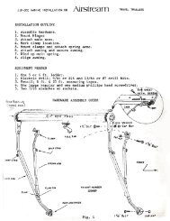
MANUAL ANTENNA<br />
Raising Antenna to Operating Position<br />
Turn elevating crank in “UP” direction until some<br />
resistance to turning is noted. Antenna is now in<br />
operating position.<br />
Rotating Antenna<br />
Make sure antenna is in “UP” position. Pull down on<br />
directional handle with both hands until it disengages<br />
ceiling plate and rotate for best picture and sound<br />
on television set.<br />
Raising Antenna<br />
Rotating Antenna<br />
G<br />
NOTICE: The Yellow wire is fused with a 10-amp in-line fuse at the 12-volt<br />
positive.<br />
Lowering Antenna to Travel Position<br />
Rotate antenna until pointer on directional handle<br />
aligns with pointer on ceiling plate. Turn elevating<br />
crank in the “Down” direction until resistance is<br />
Lowering Antenna<br />
G - 17