Frequency domain seismic forward modelling: A tool for waveform ...
Frequency domain seismic forward modelling: A tool for waveform ...
Frequency domain seismic forward modelling: A tool for waveform ...

You also want an ePaper? Increase the reach of your titles
YUMPU automatically turns print PDFs into web optimized ePapers that Google loves.
U 11<br />
0<br />
U 15<br />
L 11<br />
U 55<br />
U 22<br />
U 25<br />
L 22<br />
L 33<br />
L 44<br />
U 33<br />
0<br />
U 35<br />
U 44<br />
L 15 L 25 L 35 L 45<br />
L 55<br />
U 45<br />
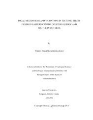
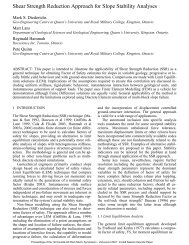
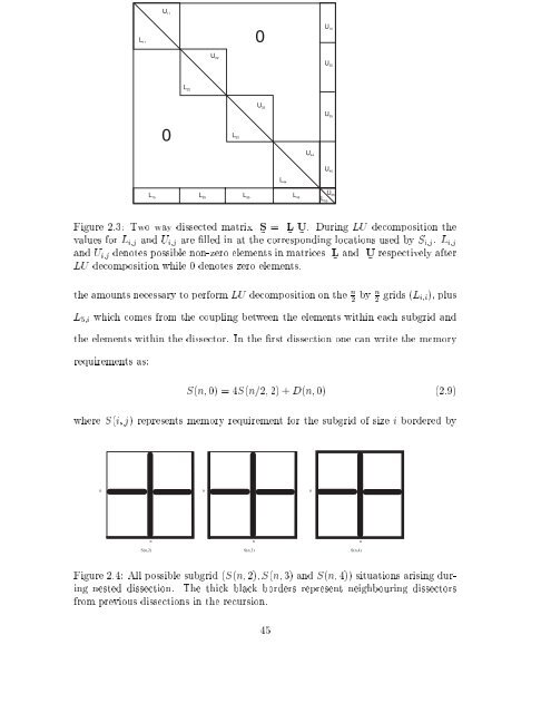
Figure 2.3: Two way dissected matrix S ~<br />
= L ~<br />
U ~<br />
. During LU decomposition the<br />
values <strong>for</strong> L i;j and U i;j are lled in at the corresponding locations used by S i;j . L i;j<br />
and U i;j denotes possible non-zero elements in matrices L ~<br />
and U ~<br />
respectively after<br />
LU decomposition while 0 denotes zero elements.<br />
the amounts necessary to per<strong>for</strong>m LU decomposition on the n 2<br />
by n 2 grids (L i;i), plus<br />
L 5;i which comes from the coupling between the elements within each subgrid and<br />
the elements within the dissector. In the rst dissection one can write the memory<br />
requirements as:<br />
S(n; 0) = 4S(n=2; 2) + D(n; 0) (2.9)<br />
where S(i; j) represents memory requirement <strong>for</strong> the subgrid of size i bordered by<br />
n<br />
n<br />
n<br />
n<br />
n<br />
n<br />
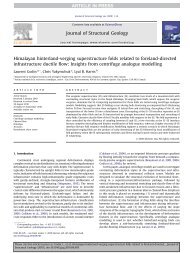
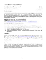
S(n,2) S(n,3) S(n,4)<br />
Figure 2.4: All possible subgrid (S(n; 2);S(n; 3) and S(n; 4)) situations arising during<br />
nested dissection. The thick black borders represent neighbouring dissectors<br />
from previous dissections in the recursion.<br />
45