GAL20V8 Data Sheet - ZMiTAC
GAL20V8 Data Sheet - ZMiTAC
GAL20V8 Data Sheet - ZMiTAC

Create successful ePaper yourself
Turn your PDF publications into a flip-book with our unique Google optimized e-Paper software.
Specifications <strong>GAL20V8</strong><br />
ELECTRONIC SIGNATURE<br />
An electronic signature is provided in every <strong>GAL20V8</strong> device. It<br />
contains 64 bits of reprogrammable memory that can contain user<br />
defined data. Some uses include user ID codes, revision numbers,<br />
or inventory control. The signature data is always available<br />
to the user independent of the state of the security cell.<br />
NOTE: The electronic signature is included in checksum calculations.<br />
Changing the electronic signature will alter the checksum.<br />
SECURITY CELL<br />
A security cell is provided in the <strong>GAL20V8</strong> devices to prevent unauthorized<br />
copying of the array patterns. Once programmed, this<br />
cell prevents further read access to the functional bits in the device.<br />
This cell can only be erased by re-programming the device,<br />
so the original configuration can never be examined once this cell<br />
is programmed. The Electronic Signature is always available to<br />
the user, regardless of the state of this control cell.<br />
LATCH-UP PROTECTION<br />
<strong>GAL20V8</strong> devices are designed with an on-board charge pump<br />
to negatively bias the substrate. The negative bias minimizes the<br />
potential of latch-up caused by negative input undershoots.<br />
Additionally, outputs are designed with n-channel pull-ups instead<br />
of the traditional p-channel pull-ups in order to eliminate latch-up<br />
due to output overshoots.<br />
OUTPUT REGISTER PRELOAD<br />
When testing state machine designs, all possible states and state<br />
transitions must be verified in the design, not just those required<br />
in the normal machine operations. This is because, in system<br />
operation, certain events occur that may throw the logic into an<br />
illegal state (power-up, line voltage glitches, brown-outs, etc.). To<br />
test a design for proper treatment of these conditions, a way must<br />
be provided to break the feedback paths, and force any desired<br />
(i.e., illegal) state into the registers. Then the machine can be<br />
sequenced and the outputs tested for correct next state conditions.<br />
<strong>GAL20V8</strong> devices include circuitry that allows each registered<br />
output to be synchronously set either high or low. Thus, any<br />
present state condition can be forced for test sequencing. If<br />
necessary, approved GAL programmers capable of executing text<br />
vectors perform output register preload automatically.<br />
INPUT BUFFERS<br />
<strong>GAL20V8</strong> devices are designed with TTL level compatible input<br />
buffers. These buffers have a characteristically high impedance,<br />
and present a much lighter load to the driving logic than bipolar<br />
TTL devices.<br />
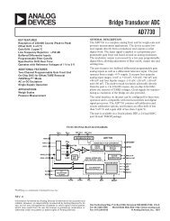
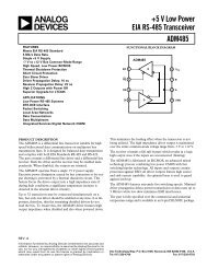
The <strong>GAL20V8</strong> input and I/O pins have built-in active pull-ups. As<br />
a result, unused inputs and I/O's will float to a TTL "high" (logical<br />
"1"). Lattice Semiconductor recommends that all unused<br />
inputs and tri-stated I/O pins be connected to another active input,<br />
V CC, or Ground. Doing this will tend to improve noise immunity<br />
and reduce I CC for the device.<br />
DEVICE PROGRAMMING<br />
GAL devices are programmed using a Lattice Semiconductorapproved<br />
Logic Programmer, available from a number of manufacturers.<br />
Complete programming of the device takes only a few<br />
seconds. Erasing of the device is transparent to the user, and is<br />
done automatically as part of the programming cycle.<br />
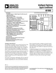
Input Current (uA)<br />
0<br />
-20<br />
-40<br />
-60<br />
0<br />
Typical Input Pull-up Characteristic<br />
1.0 2.0 3.0 4.0 5.0<br />
Input Voltage (Volts)<br />
16