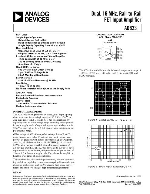
AD823 Dual, 16MHz, Rail-to-Rail FET Input Amplifier
AD823 Dual, 16MHz, Rail-to-Rail FET Input Amplifier
AD823 Dual, 16MHz, Rail-to-Rail FET Input Amplifier

You also want an ePaper? Increase the reach of your titles
YUMPU automatically turns print PDFs into web optimized ePapers that Google loves.
<strong>AD823</strong>–Typical Characteristics801007060V S = +5V314 UNITS = 40µV908070V S = +5V317 UNITS = 0.4pA5060UNITS4030UNITS504020302010100–200 –150 –100 –50 0 50 100 150 200INPUT OFFSET VOLTAGE – µV001 2 3 4 5 6 7 8 9 10INPUT BIAS CURRENT – pAFigure 4. Typical Distribution of <strong>Input</strong> Offset VoltageFigure 7. Typical Distribution of <strong>Input</strong> Bias CurrentUNITS22201816141210864V S = +5V–55°C TO +125°C103 UNITSINPUT BIAS CURRENT – pA10k1k100101V S = +5VV CM = 0V20–6 –5 –4 –3 –2 –1 0 1 2 3 4 5 6 7INPUT OFFSET VOLTAGE DRIFT – µV/°C0.1025 50 75 100 125TEMPERATURE – °CFigure 5. Typical Distribution of <strong>Input</strong> Offset Voltage DriftFigure 8. <strong>Input</strong> Bias Current vs. Temperature31k2V S = +5VV S = ±15VINPUT BIAS CURRENT – pA10–1–2–3INPUT BIAS CURRENT – pA100101–4–5–4 –3 –2 –1 0 1 2 3 4 5COMMON MODE VOLTAGE – Volts0.1–16–12 –8 –4 0 4 8 12 16COMMON MODE VOLTAGE – VoltsFigure 6. <strong>Input</strong> Bias Current vs. Common-Mode VoltageFigure 9. <strong>Input</strong> Bias Current vs. Common-Mode Voltage–6–REV. 0
<strong>AD823</strong>Since the input stage uses n-channel J<strong>FET</strong>s, input current duringnormal operation is negative; the current flows out from theinput terminals. If the input voltage is driven more positive than+V S – 0.4 V, the input current will reverse direction as internaldevice junctions become forward biased. This is illustrated inFigure 6.A current limiting resis<strong>to</strong>r should be used in series with the inpu<strong>to</strong>f the <strong>AD823</strong> if there is a possibility of the input voltage exceedingthe positive supply by more than 300 mV, or if an inputvoltage will be applied <strong>to</strong> the <strong>AD823</strong> when ±V S = 0. The amplifierwill be damaged if left in that condition for more than 10seconds. A 1 kΩ resis<strong>to</strong>r allows the amplifier <strong>to</strong> withstand up <strong>to</strong>10 volts of continuous overvoltage, and increases the input voltagenoise by a negligible amount.<strong>Input</strong> voltages less than –V S are a completely different s<strong>to</strong>ry.The amplifier can safely withstand input voltages 20 volts belowthe minus supply voltage as long as the <strong>to</strong>tal voltage from thepositive supply <strong>to</strong> the input terminal is less than 36 volts. Inaddition, the input stage typically maintains picoamp level inputcurrents across that input voltage range.The <strong>AD823</strong> is designed for 16 nV/√Hz wideband input voltagenoise and maintains low noise performance <strong>to</strong> low frequencies(refer <strong>to</strong> Figure 15). This noise performance, along with the<strong>AD823</strong>’s low input current and current noise means that the<strong>AD823</strong> contributes negligible noise for applications with sourceresistances greater than 10 kΩ and signal bandwidths greaterthan 1 kHz.OUTPUT CHARACTERISTICSThe <strong>AD823</strong>’s unique bipolar rail-<strong>to</strong>-rail output stage swingswithin 25 mV of the supplies with no external resistive load. The<strong>AD823</strong>’s approximate output saturation resistance is 25 Ωsourcing and sinking. This can be used <strong>to</strong> estimate output saturationvoltage when driving heavier current loads. For instance,when driving 5 mA, the saturation voltage <strong>to</strong> the rails will be approximately125 mV.If the <strong>AD823</strong>’s output is driven hard against the output saturationvoltage, it will recover within 250 ns of the input returning<strong>to</strong> the amplifier’s linear operating region.A/D DriverThe rail-<strong>to</strong>-rail output of the <strong>AD823</strong> makes it useful as an A/Ddriver in a single supply system. Because it is a dual op amp, itcan be used <strong>to</strong> drive both the analog input of the A/D along withits reference input. The high impedance <strong>FET</strong> input of the<strong>AD823</strong> is well suited for minimally loading of high output impedancedevices.Figure 38 shows a schematic of an <strong>AD823</strong> being used <strong>to</strong> driveboth the input and reference input of an AD1672, a 12-bit3 MSPS single supply A/D converter. One amplifier is configuredas a unity gain follower <strong>to</strong> drive the analog input of theAD1672 which is configured <strong>to</strong> accept an input voltage thatranges from 0 <strong>to</strong> 2.5 V.V INV REF(1.25V)1k2356+5VA841k1<strong>AD823</strong>70.1µF+5VA +5VD +5VD10µF 0.1 0.1µF µF10µF28 19+V CC +V DD20REFOUT21AIN1221549.9ΩAIN2CLOCK2324252627AD1672REFININ COMNCOMP2NCOMP1ACOM16REFDCOM COM19 18131412111098765432110µFOTRBIT1 (MSB)BIT2BIT3BIT4BIT5BIT6BIT7BIT8BIT9BIT10BIT11BIT12 (LSB)0.1µFFigure 38. <strong>AD823</strong> Driving <strong>Input</strong> and Reference of theAD1672, a 12-Bit 3 MSPS A/D ConverterThe other amplifier is configured as a gain of two <strong>to</strong> drive thereference input from a 1.25 V reference. Although the AD1672has its own internal reference, there are systems that requiregreater accuracy than the internal reference provides. On theother hand, if the AD1672 internal reference is used, the second<strong>AD823</strong> amplifier can be used <strong>to</strong> buffer the reference voltage fordriving other circuitry while minimally loading the referencesource.The circuit was tested with a 500 kHz sine wave input that washeavily low pass filtered (60 dB) <strong>to</strong> minimize the harmonic contentat the input <strong>to</strong> the <strong>AD823</strong>. The digital output of theAD1672 was analyzed by performing an FFT.During the testing, it was observed that at 500 kHz, the outpu<strong>to</strong>f the <strong>AD823</strong> cannot go below about 350 mV (operating withnegative supply at ground) without seriously degrading the secondharmonic dis<strong>to</strong>rtion. Another test was performed with a200 Ω pull-down resis<strong>to</strong>r <strong>to</strong> ground that allowed the output <strong>to</strong>go as low as 200 mV without seriously affecting the second harmonicdis<strong>to</strong>rtion. There was, however, a slight increase in thethird harmonic term with the resis<strong>to</strong>r added, but it was still lessthan the second harmonic.REV. 0 –13–
<strong>AD823</strong>Figure 39 is an FFT plot of the results of driving the AD1672with the <strong>AD823</strong> with no pull-down resis<strong>to</strong>r. The input amplitudewas 2.15 V p-p and the lower voltage excursion was350 mV. The input frequency was 490 kHz, which was chosen<strong>to</strong> spread the location of the harmonics.The dis<strong>to</strong>rtion analysis is important for systems requiring goodfrequency domain performance. Other systems may requiregood time domain performance. The noise and settling timeperformance of the <strong>AD823</strong> will provide the necessary informationfor its applicability for these systems.15dB/DIV5 6149 7V IN = 2.15Vp-pG = +1F I = 490kHzFigure 39. FFT of AD1672 Output Driven by <strong>AD823</strong>3 Volt, Single Supply Stereo Headphone DriverThe <strong>AD823</strong> exhibits good current drive and THD+N performance,even at 3 V single supplies. At 20 kHz, <strong>to</strong>tal harmonicdis<strong>to</strong>rtion plus noise (THD+N) equals –62 dB (0.079%) for a300 mV p-p output signal. This is comparable <strong>to</strong> other singlesupply op amps which consume more power and cannot run on3 V power supplies.In Figure 40, each channel’s input signal is coupled via a 1 µFMylar capaci<strong>to</strong>r. Resis<strong>to</strong>r dividers set the dc voltage at the noninvertinginputs so that the output voltage is midway betweenthe power supplies (+1.5 V). The gain is 1.5. Each half of the<strong>AD823</strong> can then be used <strong>to</strong> drive a headphone channel. A 5 Hzhigh-pass filter is realized by the 500 µF capaci<strong>to</strong>rs and theheadphones, which can be modeled as 32 ohm load resis<strong>to</strong>rs <strong>to</strong>ground. This ensures that all signals in the audio frequencyrange (20 Hz–20 kHz) are delivered <strong>to</strong> the headphones.23 8CHANNEL 1CHANNEL 295.3kΩ1µFMYLAR95.3k1µFMYLAR+3V95.3k47.5k3 81/2<strong>AD823</strong>210k10k14.99k4.99k647.5k 1/2<strong>AD823</strong> 75 40.1µF+500µFHEADPHONES32Ω IMPEDANCE500µF+0.1µFFigure 40. 3 Volt Single Supply Stereo Headphone DriverSecond Order Low-Pass FilterFigure 41 depicts the <strong>AD823</strong> configured as a second orderButterworth low-pass filter. With the values as shown, the cornerfrequency will be 200 kHz. The equations for componentselection are shown below:R1 = R2 = user selected (typical values: 10 kΩ <strong>to</strong> 100 kΩ).V INC1( farads ) =R120kR220kC128pF1.4142 πf cu<strong>to</strong>ff R1 ; C2 = 0.7072 πf cu<strong>to</strong>ff R1C256pF+5VC30.1µF1/2<strong>AD823</strong>–5VC40.1µF50pFFigure 41. Second Order Low-Pass FilterLRV OUTA plot of the filter is shown below; better than 50 dB of high frequencyrejection is provided.–14–REV. 0
<strong>AD823</strong>HIGH FREQUENCY REJECTION – dB0–10–20–30–40–50–601kV DB – V OUT10k 100k 1M 10M 100MFREQUENCY – HzFigure 42. Frequency Response of FilterSingle-Supply Half-Wave and Full-Wave RectifiersAn <strong>AD823</strong> configured as a unity gain follower and operatedwith a single supply can be used as a simple half-wave rectifier.The <strong>AD823</strong>’s inputs maintain picoamp level input currents evenwhen driven well below the minus supply. The rectifier puts thatbehavior <strong>to</strong> good use, maintaining an input impedance of over10 11 Ω for input voltages from 1 volt from the positive supply <strong>to</strong>20 volts below the negative supply.The full- and half-wave rectifier shown in Figure 43 operates asfollows: when V IN is above ground, R1 is bootstrapped throughthe unity gain follower A1 and the loop of amplifier A2. Thisforces the inputs of A2 <strong>to</strong> be equal, thus no current flowsthrough R1 or R2, and the circuit output tracks the input. WhenV IN is below ground, the output of A1 is forced <strong>to</strong> ground. Thenoninverting input of amplifier A2 sees the ground level outpu<strong>to</strong>f A1, therefore, A2 operates as a unity gain inverter. The outputat node C is then a full-wave rectified version of the input.Node B is a buffered half-wave rectified version of the input.<strong>Input</strong> voltage supply <strong>to</strong> ±18 volts can be rectified, depending onthe voltage supply used.+V S0.01µFA831V IN A121/24<strong>AD823</strong>ABC10090100%R1100kΩ2V 2V200µs2V65A2R2100kΩ71/2<strong>AD823</strong>FULL-WAVERECTIFIED OUTPUTBHALF-WAVERECTIFIED OUTPUTFigure 43. Single Supply Half- and Full-Wave RectifierCREV. 0 –15–
<strong>AD823</strong>OUTLINE DIMENSIONSDimensions shown in inches and (mm).8-Lead Plastic DIP(N-8)PIN 10.165±0.01(4.19±0.25)85140.39 (9.91) MAX0.25(6.35)0.31(7.87)0.035±0.01(0.89±0.25)0.30 (7.62)REFC2035–7.5–5/950.125(3.18)MIN0.018±0.003(0.46±0.08)0.10(2.54)BSC0.033(0.84)NOM0.18±0.03(4.57±0.76)SEATINGPLANE0.011±0.003(0.28±0.08)15°0°8-Lead Plastic SOIC(SO-8)PIN 181540.1574 (4.00)0.1497 (3.80)0.2440 (6.20)0.2284 (5.80)0.0098 (0.25)0.0040 (0.10)0.1968 (5.00)0.1890 (4.80)0.0500(1.27)BSC0.0192 (0.49)0.0138 (0.35)0.0688 (1.75)0.0532 (1.35)0.0098 (0.25)0.0075 (0.19)8°0°0.0196 (0.50)x 45°0.0099 (0.25)0.0500 (1.27)0.0160 (0.41)PRINTED IN U.S.A.–16–REV. 0