AD7730 Bridge Transducer ADC - ZMiTAC
AD7730 Bridge Transducer ADC - ZMiTAC
AD7730 Bridge Transducer ADC - ZMiTAC

Create successful ePaper yourself
Turn your PDF publications into a flip-book with our unique Google optimized e-Paper software.
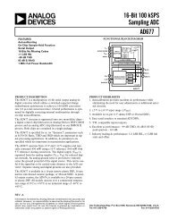
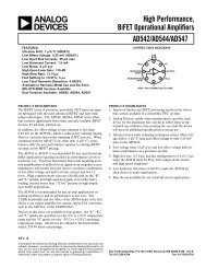
aKEY FEATURESResolution of 230,000 Counts (Peak-to-Peak)Offset Drift: 5 nV/CGain Drift: 2␣ ppm/CLine Frequency Rejection: >150␣ dBBuffered Differential InputsProgrammable Filter CutoffsSpecified for Drift Over TimeOperates with Reference Voltages of 1␣ V to 5␣ VADDITIONAL FEATURESTwo-Channel Programmable Gain Front EndOn-Chip DAC for Offset/TARE RemovalFASTStep* ModeAC or DC ExcitationSingle Supply OperationAPPLICATIONSWeigh ScalesPressure Measurement<strong>Bridge</strong> <strong>Transducer</strong> <strong>ADC</strong><strong>AD7730</strong>GENERAL DESCRIPTIONThe <strong>AD7730</strong> is a complete analog front end for weigh-scale andpressure measurement applications. The device accepts lowlevelsignals directly from a transducer and outputs a serialdigital word. The input signal is applied to a proprietary programmablegain front end based around an analog modulator.The modulator output is processed by a low pass programmabledigital filter, allowing adjustment of filter cutoff, output rate andsettling time.The part features two buffered differential programmable gainanalog inputs as well as a differential reference input. The partoperates from a single +5␣ V supply. It accepts four unipolaranalog input ranges: 0 mV to +10␣ mV, +20␣ mV, +40␣ mV and+80␣ mV and four bipolar ranges: ±10␣ mV, ±20␣ mV, ±40␣ mVand ±80␣ mV. The peak-to-peak resolution achievable directlyfrom the part is 1 in 230,000 counts. An on-chip 6-bit DACallows the removal of TARE voltages. Clock signals for synchronizingac excitation of the bridge are also provided.The serial interface on the part can be configured for three-wireoperation and is compatible with microcontrollers and digitalsignal processors. The <strong>AD7730</strong> contains self-calibration andsystem calibration options, and features an offset drift of lessthan 5 nV/°C and a gain drift of less than 2 ppm/°C.The part is available in a 24-pin plastic DIP, a 24-lead SOICand 24-lead TSSOP package.FUNCTIONAL BLOCK DIAGRAMAV DD DV DD REF IN(–) REF IN(+)VBIASREFERENCE DETECT<strong>AD7730</strong>AIN1(+)AIN1(–)MUX100nAAV DDBUFFER++/–PGASIGMA-DELTA A/D CONVERTERSIGMA-DELTAMODULATORPROGRAMMABLEDIGITALFILTERSTANDBYSYNCAIN2(+)/D1AIN2(–)/D0100nAAGND6-BITDACSERIAL INTERFACEAND CONTROL LOGICCLOCKGENERATIONMCLK INMCLK OUTREGISTER BANKSCLKACXACXACEXCITATIONCLOCKCALIBRATIONMICROCONTROLLERCSDINDOUTAGNDDGNDPOLRDYRESET*FASTStep is a trademark of Analog Devices, Inc.REV. 0Information furnished by Analog Devices is believed to be accurate andreliable. However, no responsibility is assumed by Analog Devices for itsuse, nor for any infringements of patents or other rights of third partieswhich may result from its use. No license is granted by implication orotherwise under any patent or patent rights of Analog Devices.One Technology Way, P.O. Box 9106, Norwood, MA 02062-9106, U.S.A.Tel: 617/329-4700 World Wide Web Site: http://www.analog.comFax: 617/326-8703 © Analog Devices, Inc., 1997
<strong>AD7730</strong>–SPECIFICATIONS (AV DD = +5␣ V, DV DD = +3␣ V or +5␣ V; REF IN(+) = AV DD ; REF␣ IN(–) = AGND = DGND =0␣ V; f CLK IN = 4.9152 MHz. All specifications T MIN to T MAX unless otherwise noted.)Parameter B Version 1 Units Conditions/CommentsSTATIC PERFORMANCE (CHP = 1)No Missing Codes 2 24 Bits minOutput Noise and Update Rates 2 See Tables I & IIIntegral Nonlinearity 18 ppm of FSR maxOffset Error 2 See Note 3 Offset Error and Offset Drift Refer to BothOffset Drift vs. Temperature 2 5 nV/°C typ Unipolar Offset and Bipolar Zero ErrorsOffset Drift vs. Time 4 25 nV/1000␣ Hours typPositive Full-Scale Error 2, 5 See Note 3Positive Full-Scale Drift vs Temp 2, 6, 7 2 ppm of FS/°C maxPositive Full-Scale Drift vs Time 4 10 ppm of FS/1000 Hours typGain Error 2, 8 See Note 3Gain Drift vs. Temperature 2, 6, 9 2 ppm/°C maxGain Drift vs. Time 4 10 ppm/1000 Hours typBipolar Negative Full-Scale Error 2 See Note 3Negative Full-Scale Drift vs. Temp 2, 6 2 ppm of FS/°C maxPower Supply Rejection 120 dB typ Measured with Zero Differential VoltageCommon-Mode Rejection (CMR) 120 dB min At DC. Measured with Zero Differential VoltageAnalog Input DC Bias Current 2 50 nA maxAnalog Input DC Bias Current Drift 2 100 pA/°C typAnalog Input DC Offset Current 2 10 nA maxAnalog Input DC Offset Current Drift 2 50 pA/°C typSTATIC PERFORMANCE (CHP = 0) 2No Missing Codes 24 Bits min SKIP = 0 10Output Noise and Update RatesSee Tables III & IVIntegral Nonlinearity 18 ppm of FSR maxOffset Error See Note 3 Offset Error and Offset Drift Refer to BothOffset Drift vs. Temperature 6 0.5 µV/°C typ Unipolar Offset and Bipolar Zero ErrorsOffset Drift vs. Time 4 2.5 µV/1000␣ Hours typPositive Full-Scale Error 5 See Note 3Positive Full-Scale Drift vs. Temp 6, 7 0.6 µV/°C typPositive Full-Scale Drift vs. Time 4 3 µV/1000 Hours typGain Error 8 See Note 3Gain Drift vs. Temperature 6, 9 2 ppm/°C typGain Drift vs. Time 4 10 ppm/1000 Hours typBipolar Negative Full-Scale Error See Note 3Negative Full-Scale Drift vs. Temp 0.6 µV/°C typPower Supply Rejection 90 dB typ Measured with Zero Differential VoltageCommon-Mode Rejection (CMR) on AIN 100 dB typ At DC. Measured with Zero Differential VoltageCMR on REF IN 120 dB typ At DC. Measured with Zero Differential VoltageAnalog Input DC Bias Current 60 nA maxAnalog Input DC Bias Current Drift 150 pA/°C typAnalog Input DC Offset Current 30 nA maxAnalog Input DC Offset Current Drift 100 pA/°C typANALOG INPUTS/REFERENCE INPUTSNormal-Mode 50 Hz Rejection 2 88 dB min From 49 Hz to 51 HzNormal-Mode 60 Hz Rejection 2 88 dB min From 59 Hz to 61 HzCommon-Mode 50 Hz Rejection 2 120 dB min From 49 Hz to 51 HzCommon-Mode 60 Hz Rejection 2 120 dB min From 59 Hz to 61 HzAnalog InputsDifferential Input Voltage Ranges 11Assuming 2.5 V or 5 V Reference withHIREF Bit Set Appropriately0 to +10 or ± 10 mV nom Gain = 2500 to +20 or ± 20 mV nom Gain = 1250 to +40 or ± 40 mV nom Gain = 62.50 to +80 or ± 80 mV nom Gain = 31.25Absolute/Common-Mode Voltage 12 AGND + 1.2 V V minAV DD – 0.95␣ V V maxReference InputREF IN(+) – REF IN(–) Voltage +2.5 V nom HIREF Bit of Mode Register = 0REF IN(+) – REF IN(–) Voltage +5 V nom HIREF Bit of Mode Register = 1Absolute/Common-Mode Voltage 13 AGND – 30␣ mV V minAV DD + 30␣ mV V maxNO REF Trigger Voltage 0.3 V min NO REF Bit Active If V REF Below This Voltage0.65 V max NO REF Bit Inactive If V REF Above This Voltage–2– REV. 0
<strong>AD7730</strong>Parameter B Version 1 Units Conditions/CommentsLOGIC INPUTSInput Current ± 10 µA maxAll Inputs Except SCLK and MCLK INV INL , Input Low Voltage 0.8 V max DV DD = +5␣ VV INL , Input Low Voltage 0.4 V max DV DD = +3␣ VV INH , Input High Voltage 2.0 V minSCLK Only (Schmitt Trigerred Input)V T+ 1.4/3 V min to V max DV DD = +5␣ VV T+ 1/2.5 V min to V max DV DD = +3␣ VV T– 0.8/1.4 V min to V max DV DD = +5␣ VV T– 0.4/1.1 V min to V max DV DD = +3␣ VV T+ – V T– 0.4/0.8 V min to V max DV DD = +5␣ VV T+ – V T– 0.4/0.8 V min to V max DV DD = +3␣ VMCLK IN OnlyV INL , Input Low Voltage 0.8 V max DV DD = +5␣ VV INL , Input Low Voltage 0.4 V max DV DD = +3␣ VV INH , Input High Voltage 3.5 V min DV DD = +5␣ VV INH , Input High Voltage 2.5 V min DV DD = +3␣ VLOGIC OUTPUTS (Including MCLK OUT)V OL , Output Low Voltage I SINK = 800␣ µA Except for MCLK OUT 14 ;0.4 V max V 15 DD = +5␣ VV OL , Output Low Voltage I SINK = 100␣ µA Except for MCLK OUT 14 ;0.4 V max V 15 DD = +3␣ VV OH , Output High Voltage I SOURCE = 200 µA Except for MCLK OUT 14 ;4.0 V min V 15 DD = +5␣ VV OH , Output High Voltage I SOURCE = 100 µA Except for MCLK OUT 14 ;V DD – 0.6 V V min V 15 DD = +3␣ VFloating State Leakage Current ± 10 µA maxFloating State Output Capacitance 2 6 pF typTRANSDUCER BURNOUTAIN1(+) Current –100 nA nomAIN1(–) Current 100 nA nomInitial Tolerance @ 25°C ± 10 % typDrift 2 0.1 %/°C typOFFSET (TARE) DACResolution 6 BitLSB Size 2.3/2.6 mV min/mV max 2.5 mV Nominal with 5 V Reference (REF IN/2000)DAC Drift 16 2.5 ppm/°C maxDAC Drift vs. Time 4, 16 25 ppm/1000 Hours typDifferential Linearity –0.25/+0.75 LSB max Guaranteed MonotonicSYSTEM CALIBRATIONPositive Full-Scale Calibration Limit 17 1.05 × FS V max FS Is the Nominal Full-Scale Voltage(10 mV, 20 mV, 40 mV or 80 mV)Negative Full-Scale Calibration Limit 17 –1.05 × FS V maxOffset Calibration Limit 18 –1.05 × FS V maxInput Span 17 0.8 × FS V min2.1 × FS V maxPOWER REQUIREMENTSPower Supply VoltagesAV DD – AGND Voltage +4.75 to +5.25 V min to V maxDV DD Voltage +2.7 to +5.25 V min to V max With AGND = 0 VPower Supply CurrentsExternal MCLK. Digital I/Ps = 0 V or DV DDAV DD Current (Normal Mode) 10.3 mA max All Input Ranges Except 0 mV to +10 mV and ± 10 mVAV DD Current (Normal Mode) 22.3 mA max Input Ranges of 0 mV to +10 mV and ± 10 mV OnlyDV DD Current (Normal Mode) 1.3 mA max DV DD of 2.7 V to 3.3 VDV DD Current (Normal Mode) 2.7 mA max DV DD of 4.75 V to 5.25 VAV DD + DV DD Current (Standby Mode) 25 µA max Typically 10␣ µA. External MCLK IN = 0 V or DV DDPower DissipationAV DD = DV DD = +5␣ V. Digital I/Ps = 0 V or DV DDNormal Mode 65 mW max All Input Ranges Except 0 mV to +10 mV and ± 10 mV125 mW max Input Ranges of 0 mV to +10 mV and ± 10 mV OnlyStandby Mode 125 µW max Typically 50␣ µW. External MCLK IN = 0 V or DV DDREV. 0–3–
<strong>AD7730</strong>NOTES11 Temperature range: –40°C to +85°C.12 Sample tested during initial release.13 The offset (or zero) numbers with CHP = 1 are typically 3 µV precalibration. Internal zero-scale calibration reduces this by about 1 µV. Offset numbers with CHP = 0 can be up to1 mV precalibration. Internal zero-scale calibration reduces this to 2 µV typical. System zero-scale calibration reduces offset numbers with CHP = 1 and CHP = 0 to the order of thenoise. Gain errors can be up to 3000 ppm precalibration with CHP = 0 and CHP = 1. Performing internal full-scale calibrations on the 80 mV range reduces the gain error to less than100 ppm for the 80 mV and 40 mV ranges, to about 250 ppm for the 20 mV range and to about 500 ppm on the 10 mV range. System full-scale calibration reduces this to the order ofthe noise. Positive and negative full-scale errors can be calculated from the offset and gain errors.14 These numbers are generated during life testing of the part.15 Positive Full-Scale Error includes Offset Errors (Unipolar Offset Error or Bipolar Zero Error) and applies to both unipolar and bipolar input ranges. See Terminology.16 Recalibration at any temperature will remove these errors.17 Full-Scale Drift includes Offset Drift (Unipolar Offset Drift or Bipolar Zero Drift) and applies to both unipolar and bipolar input ranges.18 Gain Error is a measure of the difference between the measured and the ideal span between any two points in the transfer function. The two points used to calculate the gainerror are positive full scale and negative full scale. See Terminology.19 Gain Error Drift is a span drift and is effectively the drift of the part if zero-scale calibrations only were performed.10 No Missing Codes performance with CHP = 0 and SKIP = 1 is reduced below 24 bits for SF words lower than 180 decimal.11 The analog input voltage range on the AIN1(+) and AIN2(+) inputs is given here with respect to the voltage on the AIN1(–) and AIN2(–) inputs respectively.12 The common-mode voltage range on the input pairs applies provided the absolute input voltage specification is obeyed.13 The common-mode voltage range on the reference input pair (REF IN(+) and REF IN(–)) applies provided the absolute input voltage specification is obeyed.14 These logic output levels apply to the MCLK OUT output only when it is loaded with a single CMOS load.15 V DD refers to DV DD for all logic outputs expect D0, D1, ACX and ACX where it refers to AV DD . In other words, the output logic high for these four outputs is determined by AV DD .16 This number represents the total drift of the channel with a zero input and the DAC output near full scale.17 After calibration, if the input voltage exceeds positive full scale, the converter will output all 1s. If the input is less than negative full scale, the device outputs all 0s.18 These calibration and span limits apply provided the absolute input voltage specification is obeyed. The offset calibration limit applies to both the unipolar zero point and thebipolar zero point.Specifications subject to change without notice.TIMING CHARACTERISTICS 1, 2(AV DD = +4.75␣ V to +5.25␣ V; DV DD = +2.7␣ V to +5.25 V; AGND = DGND = 0 V; f CLK IN = 4.9152 MHz;Input Logic 0 = 0 V, Logic 1 = DV DD unless otherwise noted).Limit at T MIN to T MAXParameter (B Version) Units Conditions/CommentsMaster Clock Range 1 MHz min For Specified Performance5 MHz maxt 1 50 ns min SYNC Pulse Widtht 2 50 ns min RESET Pulse WidthRead Operationt 3 0 ns min RDY to CS Setup Timet 4 0 ns min CS Falling Edge to SCLK Active Edge Setup Time 34t 5 0 ns min SCLK Active Edge to Data Valid Delay 360 ns max DV DD = +4.75 V to +5.25 V80 ns max DV DD = +2.75 V to +3.3 V4, 5t 5A 0 ns min CS Falling Edge to Data Valid Delay60 ns max DV DD = +4.75 V to +5.25 V80 ns max DV DD = +2.7 V to +3.3 Vt 6 100 ns min SCLK High Pulse Widtht 7 100 ns min SCLK Low Pulse Widtht 8 0 ns min CS Rising Edge to SCLK Inactive Edge Hold Time 36t 9 10 ns min Bus Relinquish Time after SCLK Inactive Edge 380 ns maxt 10 100 ns max SCLK Active Edge to RDY High 3, 7Write Operationt 11 0 ns min CS Falling Edge to SCLK Active Edge Setup Time 3t 12 30 ns min Data Valid to SCLK Edge Setup Timet 13 25 ns min Data Valid to SCLK Edge Hold Timet 14 100 ns min SCLK High Pulse Widtht 15 100 ns min SCLK Low Pulse Widtht 16 0 ns min CS Rising Edge to SCLK Edge Hold TimeNOTES1 Sample tested during initial release to ensure compliance. All input signals are specified with tr = tf = 5 ns (10% to 90% of DV DD ) and timed from a voltage level of 1.6 V.2 See Figures 18 and 19.3 SCLK active edge is falling edge of SCLK with POL = 1; SCLK active edge is rising edge of SCLK with POL = 0.4 These numbers are measured with the load circuit of Figure 1 and defined as the time required for the output to cross the V OL or V OH limits.5 This specification only comes into play if CS goes low while SCLK is low (POL = 1) or if CS goes low while SCLK is high (POL = 0). It is primarily required forinterfacing to DSP machines.6 These numbers are derived from the measured time taken by the data output to change 0.5␣ V when loaded with the circuit of Figure 1. The measured number is thenextrapolated back to remove effects of charging or discharging the 50 pF capacitor. This means that the times quoted in the timing characteristics are the true busrelinquish times of the part and as such are independent of external bus loading capacitances.7 RDY returns high after the first read from the device after an output update. The same data can be read again, if required, while RDY is high, although care shouldbe taken that subsequent reads do not occur close to the next output update.–4– REV. 0
<strong>AD7730</strong>ABSOLUTE MAXIMUM RATINGS*(T A = +25°C unless otherwise noted)AV DD to AGND . . . . . . . . . . . . . . . . . . . . . . . –0.3 V to +7 VAV DD to DGND . . . . . . . . . . . . . . . . . . . . . . . –0.3␣ V to +7␣ VDV DD to AGND . . . . . . . . . . . . . . . . . . . . . . . –0.3␣ V to +7␣ VDV DD to DGND . . . . . . . . . . . . . . . . . . . . . . . –0.3␣ V to +7␣ VAGND to DGND . . . . . . . . . . . . . . . . . . . . . . –5␣ V to +0.3␣ VAV DD to DV DD . . . . . . . . . . . . . . . . . . . . . . . . . –2␣ V to +5␣ VAnalog Input Voltage to AGND . . . . –0.3 V to AV DD + 0.3␣ VReference Input Voltage to AGND . . –0.3 V to AV DD + 0.3␣ VAIN/REF IN Current (Indefinite) . . . . . . . . . . . . . . . . 30 mADigital Input Voltage to DGND . . . . –0.3 V to DV DD + 0.3 VDigital Output Voltage to DGND . . . –0.3 V to DV DD + 0.3 VOutput Voltage (ACX, ACX, D0, D1) to DGND. . . . . . . . . . . . . . . . . . . . . . . . . . . . –0.3 V to AV DD + 0.3 VOperating Temperature RangeIndustrial (B Version) . . . . . . . . . . . . . . . –40°C to +85°CStorage Temperature Range . . . . . . . . . . . –65°C to +150°CJunction Temperature . . . . . . . . . . . . . . . . . . . . . . . . +150°CPlastic DIP Package, Power Dissipation . . . . . . . 450 mWθ JA Thermal Impedance . . . . . . . . . . . . . . . . . 105°C/WLead Temperature (Soldering, 10 sec) . . . . . . . +260°CTSSOP Package, Power Dissipation . . . . . . . . . . 450 mWθ JA Thermal Impedance . . . . . . . . . . . . . . . . . 128°C/WLead Temperature, SolderingVapor Phase (60 sec) . . . . . . . . . . . . . . . . . . +215°CInfrared (15 sec) . . . . . . . . . . . . . . . . . . . . . . +220°CSOIC Package, Power Dissipation . . . . . . . . . . . . 450 mWθ JA Thermal Impedance . . . . . . . . . . . . . . . . . . 75°C/WLead Temperature, SolderingVapor Phase (60 sec) . . . . . . . . . . . . . . . . . . +215°CInfrared (15 sec) . . . . . . . . . . . . . . . . . . . . . . +220°C*Stresses above those listed under Absolute Maximum Ratings may causepermanent damage to the device. This is a stress rating only; functionaloperation of the device at these or any other conditions above those listed inthe operational sections of this specification is not implied. Exposure toabsolute maximum rating conditions for extended periods may affect devicereliability.ORDERING GUIDETemperature Package PackageModel Range Description Options<strong>AD7730</strong>BN –40°C to +85°C Plastic DIP N-24<strong>AD7730</strong>BR –40°C to +85°C Small Outline R-24<strong>AD7730</strong>BRU –40°C to +85°C Thin Shrink Small Outline RU-24EVAL-<strong>AD7730</strong>EB Evaluation BoardI SINK (800µA AT DV DD = +5V100µA AT DV DD = +3V)TO OUTPUTPIN50pF+1.6VI SOURCE (200µA AT DV DD = +5V100µA AT DV DD = +3V)Figure 1. Load Circuit for Access Time and Bus Relinquish TimeCAUTIONESD (electrostatic discharge) sensitive device. Electrostatic charges as high as 4000 V readilyaccumulate on the human body and test equipment and can discharge without detection.Although the <strong>AD7730</strong> features proprietary ESD protection circuitry, permanent damage mayoccur on devices subjected to high energy electrostatic discharges. Therefore, proper ESDprecautions are recommended to avoid performance degradation or loss of functionality.WARNING!ESD SENSITIVE DEVICEREV. 0–5–
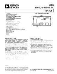
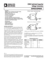
<strong>AD7730</strong>BUFFER AMPLIFIERTHE BUFFER AMPLIFIERPRESENTS A HIGH IMPEDANCEINPUT STAGE FOR THE ANALOGINPUTS ALLOWING SIGNIFICANTEXTERNAL SOURCEIMPEDANCESPROGRAMMABLE GAINAMPLIFIERTHE PROGRAMMABLE GAINAMPLIFIER ALLOWS FOURUNIPOLAR AND FOUR BIPOLARINPUT RANGES FROM+10mV TO +80mVDIFFERENTIALREFERENCETHE REFERENCE INPUT TO THEPART IS DIFFERENTIAL ANDFACILITATES RATIOMETRICOPERATION. THE REFERENCEVOLTAGE CAN BE SELECTED TOBE NOMINALLY +2.5V OR +5VSIGMA-DELTA <strong>ADC</strong>THE SIGMA-DELTAARCHITECTURE ENSURES 24 BITSNO MISSING CODES. THEENTIRE SIGMA-DELTA DELTA. <strong>ADC</strong> CANBE CHOPPED TO REMOVE DRIFTERRORSPROGRAMMABLEDIGITAL FILTERTWO STAGE FILTER THATALLOWS PROGRAMMING OFOUTPUT UPDATE RATE ANDSETTLING TIME AND WHICH HASA FAST STEP MODE(SEE FIGURE 3)SEE PAGE 24SEE PAGE 24SEE PAGE 25SEE PAGE 26SEE PAGE 26BURNOUT CURRENTSTWO 100nA BURNOUTCURRENTS ALLOW THE USERTO EASILY DETECT IF ATRANSDUCER HAS BURNTOUT OR GONE OPEN-CIRCUITSEE PAGE 25VBIASAIN1(+)AV DD DV DD REF IN(–) REF IN(+)AV DDREFERENCE DETECT<strong>AD7730</strong>SIGMA-DELTA A/D CONVERTERSTANDBYSTANDBY MODETHE STANDBY MODE REDUCESPOWER CONSUMPTION TO 5µASEE PAGE 33AIN1(–)AIN2(+)/D1AIN2(–)/D0MUXAGND+/–BUFFER6-BITDAC+PGASIGMA-DELTAMODULATORSERIAL INTERFACEAND CONTROL LOGICPROGRAMMABLEDIGITALFILTERCLOCKGENERATIONSYNCMCLK INMCLK OUTCLOCK OSCILLATORCIRCUITTHE CLOCK SOURCE FOR THEPART CAN BE PROVIDED BY ANEXTERNALLY-APPLIED CLOCK ORBY CONNECTING A CRYSTAL ORCERAMIC RESONATOR ACROSSTHE CLOCK PINSREGISTER BANKSCLKSEE PAGE 32ANALOG MULTIPLEXERA TWO-CHANNEL DIFFERENTIALMULTIPLEXER SWITCHES ONE OFTHE TWO DIFFERENTIAL INPUTCHANNELS TO THE BUFFERAMPLIFIER. THE MULTIPLEXER ISCONTROLLED VIA THE SERIALINTERFACESEE PAGE 24ACXACXACEXCITATIONCLOCKAGNDDGNDCALIBRATIONMICROCONTROLLERPOLRDYRESETCSDINDOUTSERIAL INTERFACESPI*-COMPATIBLE OR DSP-COMPATIBLE SERIAL INTERFACEWHICH CAN BE OPERATED FROMJUST THREE WIRES. ALLFUNCTIONS ON THE PARTCAN BE ACCESSED VIATHE SERIAL INTERFACESEE PAGE 35AC EXCITATIONOUTPUT DRIVERSOFFSET/TARE DACREGISTER BANKFOR AC-EXCITED BRIDGEAPPLICATIONS, THE ACXOUTPUTS PROVIDE SIGNALSTHAT CAN BE USED TO SWITCHTHE POLARITY OF THE BRIDGEEXCITATION VOLTAGESEE PAGE 41THE SECOND ANALOG INPUTCHANNEL CAN BERECONFIGURED TO BECOME TWOOUTPUT DIGITAL PORT LINESWHICH CAN BE PROGRAMMEDOVER THE SERIAL INTERFACESEE PAGE 33ALLOWS A PROGRAMMEDVOLTAGE TO BE EITHER ADDEDOR SUBTRACTED FROM THEANALOG INPUT SIGNAL BEFOREIT IS APPLIED TO THE PGASEE PAGE 24THIRTEEN REGISTERS CONTROLALL FUNCTIONS ON THE PART ANDPROVIDE STATUS INFORMATIONAND CONVERSION RESULTSSEE PAGE 11*SPI IS A TRADEMARK OF MOTOROLA, INC.Figure 2. Detailed Functional Block Diagram–6– REV. 0
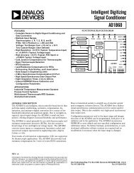
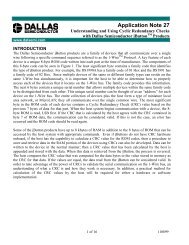
<strong>AD7730</strong>INPUT CHOPPINGSINC 3 FILTERSKIP MODE22-TAP FIR FILTERTHE ANALOG INPUT TO THE PART CAN BECHOPPED. IN CHOPPING MODE, WITHAC EXCITATION DISABLED, THE INPUTCHOPPING IS INTERNALTO THE DEVICE. INCHOPPING MODE, WITH AC EXCITATIONENABLED, THE CHOPPING IS ASSUMEDTO BE PERFORMED EXTERNAL TO THE PARTAND NO INTERNAL INPUT CHOPPING ISPERFORMED. THE INPUT CHOPPING CANBE DISABLED, IF DESIRED.THE FIRST STAGE OF THE DIGITAL FILTERINGON THE PART IS THE SINC 3 FILTER. THEOUTPUT UPDATE RATE AND BANDWIDTHOF THIS FILTER CAN BE PROGRAMMED. INSKIP MODE, THE SINC 3 FILTER IS THEONLY FILTERING PERFORMED ON THE PART.SEE PAGE 26IN SKIP MODE, THERE IS NO SECONDSTAGE OF FILTERING ON THE PART. THESINC 3 FILTER IS THE ONLY FILTERINGPERFORMED ON THE PART.SEE PAGE 29IN NORMAL OPERATING MODE, THESECOND STAGE OF THE DIGITAL FILTERINGON THE PART IS A FIXED 22-TAP FIRFILTER. IN SKIP MODE, THIS FIR FILTER ISBYPASSED. WHEN FASTSTEP MODE ISENABLED AND A STEP INPUT ISDETECTED, THE SECOND STAGE FILTERINGIS PERFORMED BY THE FILTERUNTIL THE OUTPUT OF THIS FILTERHAS FULLY SETTLED.SEE PAGE 26SEE PAGE 27SKIPANALOGINPUTCHOPBUFFERPGA +SIGMA-DELTAMODULATORSINC 3 FILTERCHOP22-TAPFIR FILTEROUTPUTSCALINGDIGITALOUTPUTBUFFERTHE INPUT SIGNAL IS BUFFEREDON-CHIP BEFORE BEING APPLIED TOTHE SAMPLING CAPACITOR OF THESIGMA-DELTA MODULATOR. THISISOLATES THE SAMPLING CAPACITORCHARGING CURRENTS FROM THEANALOG INPUT PINS.SEE PAGE 24PGA + SIGMA-DELTA MODULATORTHE PROGRAMMABLE GAIN CAPABILITYOF THE PART IS INCORPORATEDAROUND THE SIGMA-DELTA MODULATOR.THE MODULATOR PROVIDES A HIGH-FREQUENCY 1-BIT DATA STREAMTO THE DIGITAL FILTER.SEE PAGE 26OUTPUT CHOPPINGTHE OUTPUT OF THE FIRST STAGEOF FILTERING ON THE PART CANBE CHOPPED. IN CHOPPING MODE,REGARDLESS OF WHETHER ACEXCITATION IS ENABLED OR DISABLED,THE OUTPUT CHOPPING ISPERFORMED. THE CHOPPING CANBE DISABLED, IF DESIRED.SEE PAGE 26FASTSTEPFILTERFASTSTEP FILTERWHEN FASTSTEP MODE IS ENABLEDAND A STEP CHANGE ON THE INPUTHAS BEEN DETECTED, THE SECONDSTAGE FILTERING IS PERFORMED BY THEFASTSTEP FILTER UNTIL THE FIRFILTER HAS FULLY SETTLED.OUTPUT SCALINGTHE OUTPUT WORD FROM THE DIGITALFILTER IS SCALED BY THE CALIBRATIONCOEFFICIENTS BEFORE BEING PROVIDEDAS THE CONVERSION RESULT.SEE PAGE 29SEE PAGE 29Figure 3. Signal Processing ChainPIN CONFIGURATIONSCLKMCLK INMCLK OUTPOLSYNCRESETV BIASAGNDAV DDAIN1(+)AIN1(–)AIN2(+)/D1122423DGNDDV DD322 DIN421 DOUT520 RDY6<strong>AD7730</strong>19 CS7TOP VIEW(Not to Scale) 18 STANDBY8 17 ACX9 1610 15ACXREF IN(–)1114 REF IN(+)12 13 AIN2(–)/D0PIN FUNCTION DESCRIPTIONSPinNo. Mnemonic Function1 SCLK Serial Clock. Schmitt-Triggered Logic Input. An external serial clock is applied to this input to transfer serialdata to or from the <strong>AD7730</strong>. This serial clock can be a continuous clock with all data transmitted in a continuoustrain of pulses. Alternatively, it can be a noncontinuous clock with the information being transmittedto or from the <strong>AD7730</strong> in smaller batches of data.2 MCLK IN Master Clock signal for the device. This can be provided in the form of a crystal/resonator or external clock. Acrystal/resonator can be tied across the MCLK IN and MCLK OUT pins. Alternatively, the MCLK IN pincan be driven with a CMOS-compatible clock and MCLK OUT left unconnected. The part is specified with aclock input frequency of 4.9152 MHz.REV. 0–7–
<strong>AD7730</strong>PinNo. Mnemonic Function3 MCLK OUT When the master clock for the device is a crystal/resonator, the crystal/resonator is connected between MCLK␣ INand MCLK␣ OUT. If an external clock is applied to the MCLK IN, MCLK OUT provides an inverted clock signal.This clock can be used to provide a clock source for external circuits and MCLK␣ OUT is capable of drivingone CMOS load. If the user does not require it, MCLK OUT can be turned off with the CLKDIS bit of the ModeRegister. This ensures that the part is not burning unnecessary power driving capacitance on the MCLK OUT pin.4 POL Clock Polarity. Logic Input. This determines the polarity of the serial clock. If the active edge for the processoris a high-to-low SCLK transition, this input should be low. In this mode, the <strong>AD7730</strong> puts out data on theDATA OUT line in a read operation on a low-to-high transition of SCLK and clocks in data from the DATAIN line in a write operation on a high-to-low transition of SCLK. In applications with a noncontinuous serialclock (such as most microcontroller applications), this means that the serial clock should idle low betweendata transfers. If the active edge for the processor is a low-to-high SCLK transition, this input should be high.In this mode, the <strong>AD7730</strong> puts out data on the DATA OUT line in a read operation on a high-to-low transitionof SCLK and clocks in data from the DATA IN line in a write operation on a low-to-high transition ofSCLK. In applications with a noncontinuous serial clock (such as most microcontroller applications), thismeans that the serial clock should idle high between data transfers.5 SYNC Logic Input that allows for synchronization of the digital filters and analog modulators when using a numberof <strong>AD7730</strong>s. While SYNC is low, the nodes of the digital filter, the filter control logic and the calibrationcontrol logic are reset and the analog modulator is also held in its reset state. SYNC does not affect the digitalinterface but does reset RDY to a high state if it is low. While SYNC is asserted, the Mode Bits may be set upfor a subsequent operation which will commence when the SYNC pin is deasserted.6 RESET Logic Input. Active low input that resets the control logic, interface logic, digital filter, analog modulator andall on-chip registers of the part to power-on status. Effectively, everything on the part except for the clockoscillator is reset when the RESET pin is exercised.7 V BIAS Analog Output. This analog output is an internally-generated voltage used as an internal operating bias point.This output is not for use external to the <strong>AD7730</strong> and it is recommended that the user does not connect anythingto this pin.8 AGND Ground reference point for analog circuitry.9 AV DD Analog Positive Supply Voltage. The AV DD to AGND differential is 5␣ V nominal.10 AIN1(+) Analog Input Channel 1. Positive input of the differential, programmable-gain primary analog input pair. Thedifferential analog input ranges are 0 mV to +10 mV, 0 mV to +20 mV, 0 mV to +40 mV and 0 mV to +80 mVin unipolar mode, and ±10 mV, ±20 mV, ±40 mV and ±80 mV in bipolar mode.11 AIN1(–) Analog Input Channel 1. Negative input of the differential, programmable gain primary analog input pair.12 AIN2(+)/D1 Analog Input Channel 2 or Digital Output 1. This pin can be used either as part of a second analog inputchannel or as a digital output bit as determined by the DEN bit of the Mode Register. When selected as ananalog input, it is the positive input of the differential, programmable-gain secondary analog input pair. Theanalog input ranges are 0 mV to +10 mV, 0 mV to +20 mV, 0 mV to +40 mV and 0 mV to +80 mV in unipolarmode and ±10 mV, ±20 mV, ±40 mV and ±80 mV in bipolar mode. When selected as a digital output,this output can programmed over the serial interface using bit D1 of the Mode Register.13 AIN2(–)/D0 Analog Input Channel 2 or Digital Output 0. This pin can be used either as part of a second analog input channelor as a digital output bit as determined by the DEN bit of the Mode Register. When selected as an analog input, itis the negative input of the differential, programmable-gain secondary analog input pair. When selected as a digitaloutput, this output can programmed over the serial interface using bit D0 of the Mode Register.14 REF IN(+) Reference Input. Positive terminal of the differential reference input to the <strong>AD7730</strong>. REF IN(+) can lieanywhere between AV DD and AGND. The nominal reference voltage (the differential voltage between REFIN(+) and REF␣ IN(–)) should be +5 V when the HIREF bit of the Mode Register is 1 and +2.5 V when theHIREF bit of the Mode Register is 0.15 REF IN(–) Reference Input. Negative terminal of the differential reference input to the <strong>AD7730</strong>. The REF IN(–) potentialcan lie anywhere between AV DD and AGND.16 ACX Digital Output. Provides a signal that can be used to control the reversing of the bridge excitation in acexcitedbridge applications. When ACX is high, the bridge excitation is taken as normal and when ACX islow, the bridge excitation is reversed (chopped). If AC = 0 (ac mode turned off) or CHP = 0 (chop modeturned off), the ACX output remains high.17 ACX Digital Output. Provides a signal that can be used to control the reversing of the bridge excitation in acexcitedbridge applications. This output is the complement of ACX. In ac mode, this means that it toggles inanti-phase with ACX . If AC = 0 (ac mode turned off) or CHP = 0 (chop mode turned off), the ACX outputremains low. When toggling, it is guaranteed to be non-overlapping with ACX. The non-overlap interval,when both ACX and ACX are low, is one master clock cycle.–8– REV. 0
<strong>AD7730</strong>PinNo. Mnemonic Function18 STANDBY Logic Input. Taking this pin low shuts down the analog and digital circuitry, reducing current consumption tothe 5␣ µA range. The on-chip registers retain all their values when the part is in standby mode.19 CS Chip Select. Active low Logic Input used to select the <strong>AD7730</strong>. With this input hardwired low, the <strong>AD7730</strong>can operate in its three-wire interface mode with SCLK, DIN and DOUT used to interface to the device. CScan be used to select the device in systems with more than one device on the serial bus or as a frame synchronizationsignal in communicating with the <strong>AD7730</strong>.20 RDY Logic Output. Used as a status output in both conversion mode and calibration mode. In conversion mode, alogic low on this output indicates that a new output word is available from the <strong>AD7730</strong> data register. TheRDY pin will return high upon completion of a read operation of a full output word. If no data read has takenplace after an output update, the RDY line will return high prior to the next output update, remain high whilethe update is taking place and return low again. This gives an indication of when a read operation should notbe initiated to avoid initiating a read from the data register as it is being updated. In calibration mode, RDYgoes high when calibration is initiated and it returns low to indicate that calibration is complete. A number ofdifferent events on the <strong>AD7730</strong> set the RDY high and these are outlined in Table XVIII.21 DOUT Serial Data Output with serial data being read from the output shift register on the part. This output shiftregister can contain information from the calibration registers, mode register, status register, filter register,DAC register or data register, depending on the register selection bits of the Communications Register.22 DIN Serial Data Input with serial data being written to the input shift register on the part. Data from this inputshift register is transferred to the calibration registers, mode register, communications register, DAC registeror filter registers depending on the register selection bits of the Communications Register.23 DV DD Digital Supply Voltage, +3␣ V or +5 V nominal.24 DGND Ground reference point for digital circuitry.TERMINOLOGYINTEGRAL NONLINEARITYThis is the maximum deviation of any code from a straight linepassing through the endpoints of the transfer function. The endpointsof the transfer function are zero scale (not to be confusedwith bipolar zero), a point 0.5 LSB below the first code transition(000 . . . 000 to 000 . . . 001) and full scale, a point 0.5 LSBabove the last code transition (111 . . . 110 to 111 . . . 111). Theerror is expressed as a percentage of full scale.POSITIVE FULL-SCALE ERRORPositive Full-Scale Error is the deviation of the last code transition(111 . . . 110 to 111 . . . 111) from the ideal AIN(+) voltage(AIN(–) + V REF /GAIN – 3/2 LSBs). It applies to both unipolarand bipolar analog input ranges. Positive full-scale error is asummation of offset error and gain error.UNIPOLAR OFFSET ERRORUnipolar Offset Error is the deviation of the first code transitionfrom the ideal AIN(+) voltage (AIN(–) + 0.5 LSB) when operatingin the unipolar mode.BIPOLAR ZERO ERRORThis is the deviation of the midscale transition (0111 . . . 111 to1000 . . . 000) from the ideal AIN(+) voltage (AIN(–) – 0.5 LSB)when operating in the bipolar mode.GAIN ERRORThis is a measure of the span error of the <strong>ADC</strong>. It is a measureof the difference between the measured and the ideal span betweenany two points in the transfer function. The two pointsused to calculate the gain error are full scale and zero scale.REV. 0–9–BIPOLAR NEGATIVE FULL-SCALE ERRORThis is the deviation of the first code transition from the idealAIN(+) voltage (AIN(–) – V REF /GAIN + 0.5 LSB) when operatingin the bipolar mode. Negative full-scale error is a summationof zero error and gain error.POSITIVE FULL-SCALE OVERRANGEPositive Full-Scale Overrange is the amount of overhead availableto handle input voltages on AIN(+) input greater thanAIN(–) + V REF /GAIN (for example, noise peaks or excess voltagesdue to system gain errors in system calibration routines) withoutintroducing errors due to overloading the analog modulatoror overflowing the digital filter.NEGATIVE FULL-SCALE OVERRANGEThis is the amount of overhead available to handle voltages onAIN(+) below AIN(–) – V REF /GAIN without overloading theanalog modulator or overflowing the digital filter.OFFSET CALIBRATION RANGEIn the system calibration modes, the <strong>AD7730</strong> calibrates itsoffset with respect to the analog input. The Offset CalibrationRange specification defines the range of voltages the <strong>AD7730</strong>can accept and still accurately calibrate offset.FULL-SCALE CALIBRATION RANGEThis is the range of voltages that the <strong>AD7730</strong> can accept in thesystem calibration mode and still calibrate full scale correctly.INPUT SPANIn system calibration schemes, two voltages applied in sequenceto the <strong>AD7730</strong>’s analog input define the analog input range.The input span specification defines the minimum and maximuminput voltages, from zero to full scale, the <strong>AD7730</strong> canaccept and still accurately calibrate gain.
<strong>AD7730</strong>OUTPUT NOISE AND RESOLUTION SPECIFICATIONThe <strong>AD7730</strong> can be programmed to operate in either chop mode or nonchop mode. The chop mode can be enabled in ac-excited ordc-excited applications; it is optional in dc-excited applications, but chop mode must be enabled in ac-excited applications. Theseoptions are discussed in more detail in later sections. The chop mode has the advantage of lower drift numbers and better noise immunity,but the noise is approximately 20% higher for a given –3 dB frequency and output data rate. It is envisaged that the majorityof weigh-scale users of the <strong>AD7730</strong> will operate the part in chop mode to avail themselves of the excellent drift performance andnoise immunity when chopping is enabled. The following tables outline the noise performance of the part in both chop and nonchopmodes over all input ranges for a selection of output rates. Settling time refers to the time taken to get an output that is 100% settledto new value.Output Noise (CHP = 1)This mode is the primary mode of operation of the device. Table I shows the output rms noise for some typical output update ratesand –3 dB frequencies for the <strong>AD7730</strong> when used in chopping mode (CHP of Filter Register = 1) with a master clock frequency of4.9152 MHz. These numbers are typical and are generated at a differential analog input voltage of 0 V. The output update rate isselected via the SF0 to SF11 bits of the Filter Register. Table II, meanwhile, shows the output peak-to-peak resolution in counts forthe same output update rates. The numbers in brackets are the effective peak-to-peak resolution in bits (rounded to the nearest 0.5LSB). It is important to note that the numbers in Table II represent the resolution for which there will be no code flicker within asix-sigma limit. They are not calculated based on rms noise, but on peak-to-peak noise.The numbers are generated for the bipolar input ranges. When the part is operated in unipolar mode, the output noise will be thesame as the equivalent bipolar input range. As a result, the numbers in Table I will remain the same for unipolar ranges while thenumbers in Table II will change. To calculate the numbers for Table II for unipolar input ranges simply divide the peak-to-peakresolution number in counts by two or subtract one from the peak-to-peak resolution number in bits.Table I. Output Noise vs. Input Range and Update Rate (CHP = 1)Typical Output RMS Noise in nVOutput –3 dB SF Settling Time Settling Time Input Range Input Range Input Range Input RangeData Rate Frequency Word Normal Mode Fast Mode = 80 mV = 40 mV = 20 mV = 10 mV50␣ Hz 1.97␣ Hz 2048 460 ms 60 ms 115 75 55 40100␣ Hz 3.95␣ Hz 1024 230␣ ms 30␣ ms 155 105 75 60150␣ Hz 5.92␣ Hz 683 153 ms 20 ms 200 135 95 70200␣ Hz* 7.9␣ Hz 512 115␣ ms 15␣ ms 225 145 100 80400␣ Hz 15.8␣ Hz 256 57.5␣ ms 7.5␣ ms 335 225 160 110*Power-On DefaultTable II. Peak-Peak Resolution vs. Input Range and Update Rate (CHP = 1)Peak-to-Peak Resolution in Counts (Bits)Output –3 dB SF Settling Time Settling Time Input Range Input Range Input Range Input RangeData Rate Frequency Word Normal Mode Fast Mode = 80 mV = 40 mV = 20 mV = 10 mV50␣ Hz 1.97␣ Hz 2048 460 ms 60 ms 230k (18) 175k (17.5) 120k (17) 80k (16.5)100␣ Hz 3.95␣ Hz 1024 230␣ ms 30␣ ms 170k (17.5) 125k (17) 90k (16.5) 55k (16)150␣ Hz 5.92␣ Hz 683 153 ms 20 ms 130k (17) 100k (16.5) 70k (16) 45k (15.5)200␣ Hz* 7.9␣ Hz 512 115␣ ms 15␣ ms 120k (17) 90k (16.5) 65k (16) 40k (15.5)400␣ Hz 15.8␣ Hz 256 57.5␣ ms 7.5␣ ms 80k (16.5) 55k (16) 40k (15.5) 30k (15)*Power-On DefaultOutput Noise (CHP = 0)Table III shows the output rms noise for some typical output update rates and –3 dB frequencies for the <strong>AD7730</strong> when used in nonchoppingmode (CHP of Filter Register = 0) with a master clock frequency of 4.9152 MHz. These numbers are typical and are generatedat a differential analog input voltage of 0 V. The output update rate is selected via the SF0 to SF11 bits of the Filter Register.Table IV, meanwhile, shows the output peak-to-peak resolution in counts for the same output update rates. The numbers in bracketsare the effective peak-to-peak resolution in bits (rounded to the nearest 0.5 LSB). It is important to note that the numbers in TableIV represent the resolution for which there will be no code flicker within a six-sigma limit. They are not calculated based on rmsnoise, but on peak-to-peak noise.The numbers are generated for the bipolar input ranges. When the part is operated in unipolar mode, the output noise will be thesame as the equivalent bipolar input range. As a result, the numbers in Table III will remain the same for unipolar ranges while thenumbers in Table IV will change. To calculate the number for Table IV for unipolar input ranges simply divide the peak-to-peakresolution number in counts by two or subtract one from the peak-to-peak resolution number in bits.–10– REV. 0
<strong>AD7730</strong>Table III. Output Noise vs. Input Range and Update Rate (CHP = 0)Typical Output RMS Noise in nVOutput –3 dB SF Settling Time Settling Time Input Range Input Range Input Range Input RangeData Rate Frequency Word Normal Mode Fast Mode = 80 mV = 40 mV = 20 mV = 10 mV150␣ Hz 5.85␣ Hz 2048 166 ms 26.6 ms 160 110 80 60200␣ Hz 7.8␣ Hz 1536 125␣ ms 20␣ ms 190 130 95 75300␣ Hz 11.7␣ Hz 1024 83.3␣ ms 13.3␣ ms 235 145 100 80600␣ Hz 23.4␣ Hz 512 41.6␣ ms 6.6␣ ms 300 225 135 1101200␣ Hz 46.8␣ Hz 256 20.8␣ ms 3.3␣ ms 435 315 210 150Table IV. Peak-to-Peak Resolution vs. Input Range and Update Rate (CHP = 0)Peak-to-Peak Resolution in Counts (Bits)Output –3 dB SF Settling Time Settling Time Input Range Input Range Input Range Input RangeData Rate Frequency Word Normal Mode Fast Mode = 80 mV = 40 mV = 20 mV = 10 mV150␣ Hz 5.85␣ Hz 2048 166 ms 26.6 ms 165k (17.5) 120k (17) 80k (16.5) 55k (16)200␣ Hz 7.8␣ Hz 1536 125 ms 20 ms 140k (17) 100k (16.5) 70k (16) 45k (15.5)300␣ Hz 11.7␣ Hz 1024 83.3 ms 13.3 ms 115k (17) 90k (16.5) 65k (16) 40k (15.5)600␣ Hz 23.4␣ Hz 512 41.6 ms 6.6 ms 90k (16.5) 60k (16) 50k (15.5) 30k (15)1200␣ Hz 46.8␣ Hz 256 20.8 ms 3.3 ms 60k (16) 43k (15.5) 32k (15) 20k (14.5)ON-CHIP REGISTERSThe <strong>AD7730</strong> contains thirteen on-chip registers which can be accessed via the serial port of the part. These registers are summarizedin Figure 4 and in Table V and described in detail in the following sections.DINDINCOMMUNICATIONS REGISTERRS2 RS1 RS0DOUTDOUTSTATUS REGISTERDOUTDATA REGISTERDINDOUTMODE REGISTERDOUTDINFILTER REGISTERREGISTERSELECTDECODERDOUTDINDAC REGISTERDOUTDINOFFSET REGISTER (x3)DOUTDINGAIN REGISTER (x3)DOUTDINTEST REGISTERFigure 4. Register OverviewREV. 0–11–
<strong>AD7730</strong>Table V. Summary of On-Chip RegistersPower-On/ResetRegister Name Type Size Default Value FunctionCommunications Write Only 8 Bits Not Applicable All operations to other registers are initiated throughRegisterthe Communications Register. This controls whetherWEN ZERO RW1 RW0 ZERO RS2 RS1 RS0subsequent operations are read or write operationsand also selects the register for that subsequentoperation. Most subsequent operations return controlto the Communications Register except for thecontinuous read mode of operation.Status Register Read Only 8 Bits CX Hex Provides status information on conversions, calibrations,settling to step inputs, standby operation andRDY STDY STBY NOREF MS3 MS2 MS1 MS0the validity of the reference voltage.Data Register Read Only 16 Bits or 24 Bits 000000 Hex Provides the most up-to-date conversion result fromthe part. Register length can be programmed to be16 bits or 24 bits.Mode Register Read/Write 16 Bits 01B0 Hex Controls functions such as mode of operation, unipolar/bipolaroperation, controlling the function ofMD2HIREFMD1ZEROMD0RN1B/URN0DENCLKDISD1BOD0CH1WLCH0AIN2(+)/D1 and AIN2(-)/D0, burnout current,Data Register word length and disabling of MCLKOUT. It also contains the reference selection bit, therange selection bits and the channel selection bits.Filter RegisterSF11 SF10 SF9Read/WriteSF824 BitsSF7 SF6 SF5200010 HexSF4Controls the amount of averaging in the first stagefilter, selects the fast step and skip modes and controlsthe ac excitation and chopping modes on theSF3 SF2 SF1 SF0 ZERO ZERO SKIP FASTpart.ZERO ZERO AC CHP DL3 DL2 DL1 DL0DAC Register Read/Write 8 Bits 20 Hex Provides control of the amount of correction performedby the Offset/TARE DAC.ZERO ZERO DAC5 DAC4 DAC3 DAC2 DAC1 DAC0Offset Register Read/Write 24 Bits 800000 Hex Contains a 24-bit word which is the offset calibrationcoefficient for the part. The contents of this registerare used to provide offset correction on the outputfrom the digital filter. There are three Offset Registerson the part and these are associated with theinput channels as outlined in Table XIII.Gain Register Read/Write 24 Bits 59AEE7 Hex Contains a 24-bit word which is the gain calibrationcoefficient for the part. The contents of this registerare used to provide gain correction on the outputfrom the digital filter. There are three Gain Registerson the part and these are associated with the inputchannels as outlined in Table XIII.Test Register Read/Write 24 Bits 000000 Hex Controls the test modes of the part which are usedwhen testing the part. The user is advised not tochange the contents of this register.–12– REV. 0
<strong>AD7730</strong>Communications Register (RS2–RS0 = 0, 0, 0)The Communications Register is an 8-bit write-only register. All communications to the part must start with a write operation to theCommunications Register. The data written to the Communications Register determines whether the next operation is a read orwrite operation, the type of read operation, and to which register this operation takes place. For single-shot read or write operations,once the subsequent read or write operation to the selected register is complete, the interface returns to where it expects a write operationto the Communications Register. This is the default state of the interface, and on power-up or after a RESET, the <strong>AD7730</strong>is in this default state waiting for a write operation to the Communications Register. In situations where the interface sequence islost, a write operation of at least 32 serial clock cycles with DIN high, returns the <strong>AD7730</strong> to this default state by resetting thepart. Table VI outlines the bit designations for the Communications Register. CR0 through CR7 indicate the bit location, CR denotingthe bits are in the Communications Register. CR7 denotes the first bit of the data stream.Table VI. Communications RegisterCR7 CR6 CR5 CR4 CR3 CR2 CR1 CR0WEN ZERO RW1 RW0 ZERO RS2 RS1 RS0BitBitLocation Mnemonic DescriptionCR7 WEN Write Enable Bit. A 0 must be written to this bit so the write operation to the CommunicationsRegister actually takes place. If a 1 is written to this bit, the part will not clock on to subsequentbits in the register. It will stay at this bit location until a 0 is written to this bit. Once a 0 is writtento the WEN bit, the next seven bits will be loaded to the Communications Register.CR6 ZERO A zero must be written to this bit to ensure correct operation of the <strong>AD7730</strong>.CR5, CR4 RW1, RW0 Read/Write Mode Bits. These two bits determine the nature of the subsequent read/write operation.Table VII outlines the four options.Table VII. Read/Write ModeRW1 RW0 Read/Write Mode0 0 Single Write to Specified Register0 1 Single Read of Specified Register1 0 Start Continuous Read of Specified Register1 1 Stop Continuous Read ModeWith 0, 0 written to these two bits, the next operation is a write operation to the register specified bybits RS2, RS1, RS0. Once the subsequent write operation to the specified register has been completed,the part returns to where it is expecting a write operation to the Communications Register.With 0,1 written to these two bits, the next operation is a read operation of the register specifiedby bits RS2, RS1, RS0. Once the subsequent read operation to the specified register has beencompleted, the part returns to where it is expecting a write operation to the CommunicationsRegister.Writing 1,0 to these bits, sets the part into a mode of continuous reads from the register specifiedby bits RS2, RS1, RS0. The most likely registers with which the user will want to use thisfunction are the Data Register and the Status Register. Subsequent operations to the part willconsist of read operations to the specified register without any intermediate writes to the CommunicationsRegister. This means that once the next read operation to the specified register hastaken place, the part will be in a mode where it is expecting another read from that specifiedregister. The part will remain in this continuous read mode until 30 Hex has been written to theCommunications Register.When 1,1 is written to these bits (and 0 written to bits CR3 through CR0), the continuous readmode is stopped and the part returns to where it is expecting a write operation to the CommunicationsRegister. Note, the part continues to look at the DIN line on each SCLK edge duringcontinuous read mode to determine when to stop the continuous read mode. Therefore, the usermust be careful not to inadvertently exit the continuous read mode or reset the <strong>AD7730</strong> bywriting a series of 1s to the part. The easiest way to avoid this is to place a logic 0 on the DINline while the part is in continuous read mode. Once the part is in continuous read mode, theuser should ensure that an integer multiple of 8 serial clocks should have taken place beforeattempting to take the part out of continuous read mode.REV. 0–13–
<strong>AD7730</strong>BitBitLocation Mnemonic DescriptionCR3 ZERO A zero must be written to this bit to ensure correct operation of the <strong>AD7730</strong>.CR2–CR0 RS2–RS0 Register Selection Bits. RS2 is the MSB of the three selection bits. The three bits selectwhich register type the next read or write operation operates upon as shown in Table VIII.Table VIII. Register SelectionRS2 RS1 RS0 Register0 0 0 Communications Register (Write Operation)0 0 0 Status Register (Read Operation)0 0 1 Data Register0 1 0 Mode Register0 1 1 Filter Register1 0 0 DAC Register1 0 1 Offset Register1 1 0 Gain Register1 1 1 Test RegisterStatus Register (RS2–RS0 = 0, 0, 0); Power-On/Reset Status: CX HexThe Status Register is an 8-bit read-only register. To access the Status Register, the user must write to the Communications Registerselecting either a single-shot read or continuous read mode and load bits RS2, RS1, RS0 with 0, 0, 0. Table IX outlines the bit designationsfor the Status Register. SR0 through SR7 indicate the bit location, SR denoting the bits are in the Status Register. SR7denotes the first bit of the data stream. Figure 5 shows a flowchart for reading from the registers on the <strong>AD7730</strong>. The numberin brackets indicates the power-on/reset default status of that bit.Table IX. Status RegisterSR7 SR6 SR5 SR4 SR3 SR2 SR1 SR0RDY (1) STDY (1) STBY (0) NOREF (0) MS3 (X) MS2 (X) MS1 (X) MS0 (X)BitBitLocation Mnemonic DescriptionSR7 RDY Ready Bit. This bit provides the status of the RDY flag from the part. The status and function ofthis bit is the same as the RDY output pin. A number of events set the RDY bit high as indicatedin Table XVIII.SR6 STDY Steady Bit. This bit is updated when the filter writes a result to the Data Register. If the filter isin FASTStep mode (see Filter Register section) and responding to a step input, the STDY bitremains high as the initial conversion results become available. The RDY output and bit are setlow on these initial conversions to indicate that a result is available. If the STDY is high, however,it indicates that the result being provided is not from a fully settled second-stage FIR filter. When theFIR filter has fully settled, the STDY bit will go low coincident with RDY. If the part is never placedinto its FASTStep mode, the STDY bit will go low at the first Data Register read and it is notcleared by subsequent Data Register reads.A number of events set the STDY bit high as indicated in Table XVIII. STDY is set high alongwith RDY by all events in the table except a Data Register read.SR5 STBY Standby Bit. This bit indicates whether the <strong>AD7730</strong> is in its Standby Mode or normal mode ofoperation. The part can be placed in its standby mode using the STANDBY input pin or bywriting 011 to the MD2 to MD0 bits of the Mode Register. The power-on/reset status of this bitis 0 assuming the STANDBY pin is high.SR4 NOREF No Reference Bit. If the voltage between the REF IN(+) and REF IN(–) pins is below 0.3 V, oreither of these inputs is open-circuit, the NOREF bit goes to 1. If NOREF is active on completionof a conversion, the Data Register is loaded with all 1s. If NOREF is active on completionof a calibration, updating of the calibration registers is inhibited.SR3–SR0 MS3–MS0 These bits are for factory use. The power-on/reset status of these bits vary, depending on thefactory-assigned number.–14– REV. 0
<strong>AD7730</strong>Data Register (RS2–RS0 = 0, 0, 1); Power On/Reset Status: 000000 HexThe Data Register on the part is a read-only register which contains the most up-to-date conversion result from the <strong>AD7730</strong>. Figure5 shows a flowchart for reading from the registers on the <strong>AD7730</strong>. The register can be programmed to be either 16 bits or 24 bitswide, determined by the status of the WL bit of the Mode Register. The RDY output and RDY bit of the Status Register are set lowwhen the Data Register is updated. The RDY pin and RDY bit will return high once the full contents of the register (either 16 bits or24 bits) have been read. If the Data Register has not been read by the time the next output update occurs, the RDY pin and RDY bitwill go high for at least 100 × t CLK IN , indicating when a read from the Data Register should not be initiated to avoid a transfer fromthe Data Register as it is being updated. Once the updating of the Data Register has taken place, RDY returns low.If the Communications Register data sets up the part for a write operation to this register, a write operation must actually take placein order to return the part to where it is expecting a write operation to the Communications Register (the default state of the interface).However, the 16 or 24 bits of data written to the part will be ignored by the <strong>AD7730</strong>.Mode Register (RS2–RS0 = 0, 1, 0); Power On/Reset Status: 01B0␣ HexThe Mode Register is a 16-bit register from which data can be read or to which data can be written. This register configuresthe operating modes of the <strong>AD7730</strong>, the input range selection, the channel selection and the word length of the Data Register.Table␣ X outlines the bit designations for the Mode Register. MR0 through MR15 indicate the bit location, MR denoting the bits arein the Mode Register. MR15 denotes the first bit of the data stream. The number in brackets indicates the power-on/reset defaultstatus of that bit. Figure 5 shows a flowchart for reading from the registers on the <strong>AD7730</strong> and Figure 6 shows a flowchart for writingto the registers on the part.Table X. Mode RegisterMR15 MR14 MR13 MR12 MR11 MR10 MR9 MR8MD2 (0) MD1 (0) MD0 (0) B/U (0) DEN (0) D1 (0) D0 (0) WL (1)MR7 MR6 MR5 MR4 MR3 MR2 MR1 MR0HIREF (1) ZERO (0) RN1 (1) RN0 (1) CLKDIS (0) BO (0) CH1 (0) CH0 (0)BitBitLocation Mnemonic DescriptionMR15–MR13 MD2–MD0 Mode Bits. These three bits determine the mode of operation of the <strong>AD7730</strong> as outlined inTable XI. The modes are independent, such that writing new mode bits to the Mode Registerwill exit the part from the mode in which it is operating and place it in the new requested modeimmediately after the Mode Register write. The function of the mode bits is described in moredetail below.Table XI. Operating ModesMD2 MD1 MD0 Mode of Operation0 0 0 Sync (Idle) Mode Power-On/Reset Default0 0 1 Continuous Conversion Mode0 1 0 Single Conversion Mode0 1 1 Power-Down (Standby) Mode1 0 0 Internal Zero-Scale Calibration1 0 1 Internal Full-Scale Calibration1 1 0 System Zero-Scale Calibration1 1 1 System Full-Scale CalibrationREV. 0–15–
<strong>AD7730</strong>MD2 MD1 MD0 Operating Mode0 0 0 Sync (Idle) Mode. In this mode, the modulator and filter are held in reset mode and the <strong>AD7730</strong> is notprocessing any new samples or data. Placing the part in this mode is equivalent to exerting the SYNCinput pin. However, exerting the SYNC pin does not actually force these mode bits to 0, 0, 0. The partreturns to this mode after a calibration or after a conversion in Single Conversion Mode. This is thedefault condition of these bits after Power-On/Reset.0 0 1 Continuous Conversion Mode. In this mode, the <strong>AD7730</strong> is continuously processing data and providingconversion results to the Data Register at the programmed output update rate (as determined by theFilter Register). For most applications, this would be the normal operating mode of the <strong>AD7730</strong>.0 1 0 Single Conversion Mode. In this mode, the <strong>AD7730</strong> performs a single conversion, updates the DataRegister, returns to the Sync Mode and resets the mode bits to 0, 0, 0. The result of the single conversionon the <strong>AD7730</strong> in this mode will not be provided until the full settling time of the filter has elapsed.0 1 1 Power-Down (Standby) Mode. In this mode, the <strong>AD7730</strong> goes into its power-down or standby state.Placing the part in this mode is equivalent to exerting the STANDBY input pin. However, exertingSTANDBY does not actually force these mode bits to 0, 1, 1.1 0 0 Zero-Scale Self-Calibration Mode. This activates zero-scale self-calibration on the channel selected byCH1 and CH0 of the Mode Register. This zero-scale self-calibration is performed at the selected gain oninternally shorted (zeroed) inputs. When this zero-scale self-calibration is complete, the part updates thecontents of the appropriate Offset Calibration Register and returns to Sync Mode with MD2, MD1 andMD0 returning to 0, 0, 0. The RDY output and bit go high when calibration is initiated and return lowwhen this zero-scale self-calibration is complete to indicate that the part is back in Sync Mode and readyfor further operations.1 0 1 Full-Scale Self-Calibration Mode. This activates full-scale self-calibration on the channel selected byCH1 and CH0 of the Mode Register. This full-scale self-calibration is performed at the selected gain onan internally-generated full-scale signal. When this full-scale self-calibration is complete, the part updatesthe contents of the appropriate Gain Calibration Register and Offset Calibration Register and returns toSync Mode with MD2, MD1 and MD0 returning to 0, 0, 0. The RDY output and bit go high whencalibration is initiated and return low when this full-scale self-calibration is complete to indicate that thepart is back in Sync Mode and ready for further operations.1 1 0 Zero-Scale System Calibration Mode. This activates zero scale system calibration on the channel selectedby CH1 and CH0 of the Mode Register. Calibration is performed at the selected gain on the input voltageprovided at the analog input during this calibration sequence. This input voltage should remainstable for the duration of the calibration. When this zero-scale system calibration is complete, the partupdates the contents of the appropriate Offset Calibration Register and returns to Sync Mode with MD2,MD1 and MD0 returning to 0, 0, 0. The RDY output and bit go high when calibration is initiated andreturn low when this zero-scale calibration is complete to indicate that the part is back in Sync Mode andready for further operations.1 1 1 Full-Scale System Calibration Mode. This activates full-scale system calibration on the selected inputchannel. Calibration is performed at the selected gain on the input voltage provided at the analog inputduring this calibration sequence. This input voltage should remain stable for the duration of the calibration.When this full-scale system calibration is complete, the part updates the contents of the appropriateGain Calibration Register and returns to Sync Mode with MD2, MD1 and MD0 returning to 0, 0, 0.The RDY output and bit go high when calibration is initiated and return low when this full-scale calibrationis complete to indicate that the part is back in Sync Mode and ready for further operations.–16– REV. 0
<strong>AD7730</strong>BitBitLocation Mnemonic DescriptionMR2 BO Burnout Current Bit. A 1 in this bit activates the burnout currents. When active, the burnout currentsconnect to the selected analog input pair, one source current to the AIN(+) input and one sink current tothe AIN(–) input. A 0 in this bit turns off the on-chip burnout currents.MR1–MR0 CH1–CH0 Channel Selection Bits. These bits select the analog input channel to be converted or calibrated asoutlined in Table XIII. With CH1 at 1 and CH0 at 0, the part looks at the AIN1(–) input internallyshorted to itself. This can be used as a test method to evaluate the noise performance of the part withno external noise sources. In this mode, the AIN1(–) input should be connected to an external voltagewithin the allowable common-mode range of the part. The Offset and Gain Calibration Registers onthe part are paired. There are three pairs of calibration registers labelled Register Pair 0 through RegisterPair 2. These are assigned to the input channel pairs as outlined in Table XIII.Table XIII. Channel SelectionInput Channel PairCH1 CH0 Positive Input Negative Input Calibration Register Pair0 0 AIN1(+) AIN1(–) Register Pair 00 1 AIN2(+) AIN2(–) Register Pair 11 0 AIN1(–) AIN1(–) Register Pair 01 1 AIN1(–) AIN2(–) Register Pair 2Filter Register (RS2-RS0 = 0, 1, 1); Power On/Reset Status: 200010␣ HexThe Filter Register is a 24-bit register from which data can be read or to which data can be written. This register determines theamount of averaging performed by the filter and the mode of operation of the filter. It also sets the chopping mode and the delayassociated with chopping the inputs. Table XIV outlines the bit designations for the Filter Register. FR0 through FR23 indicate thebit location, FR denoting the bits are in the Filter Register. FR23 denotes the first bit of the data stream. The number in bracketsindicates the power-on/reset default status of that bit. Figure 5 shows a flowchart for reading from the registers on the <strong>AD7730</strong> andFigure 6 shows a flowchart for writing to the registers on the part.Table XIV. Filter RegisterFR23 FR22 FR21 FR20 FR19 FR18 FR17 FR16SF11 (0) SF10 (0) SF9 (1) SF8 (0) SF7 (0) SF6 (0) SF5 (0) SF4 (0)FR15 FR14 FR13 FR12 FR11 FR10 FR9 FR8SF3 (0) SF2 (0) SF1 (0) SF0 (0) ZERO (0) ZERO (0) SKIP (0) FAST (0)FR7 FR6 FR5 FR4 FR3 FR2 FR1 FR0ZERO (0) ZERO (0) AC (0) CHP (1) DL3 (0) DL2 (0) DL1 (0) DL0 (0)BitBitLocation Mnemonic DescriptionFR23–FR12 SF11–SF0 Sinc 3 Filter Selection Bits. The <strong>AD7730</strong> contains two filters: a sinc 3 filter and an FIR filter. The 12 bitsprogrammed to SF11 through SF0 set the amount of averaging the sinc 3 filter performs. As a result,the number programmed to these 12 bits affects the –3 dB frequency and output update rate from thepart (see Filter Architecture section). The allowable range for SF words depends on whether the partis operated with CHOP on or off and SKIP on or off. Table XV outlines the SF ranges for differentsetups.–18– REV. 0
<strong>AD7730</strong>Table XV. SF RangesCHOP SKIP SF Range Output Update Rate Range (Assuming 4.9152 MHz Clock)0 0 2048 to 150 150 Hz to 2.048 kHz1 0 2048 to 75 50 Hz to 1.365 kHz0 1 2048 to 40 150 Hz to 7.6 kHz1 1 2048 to 20 50 Hz to 5.12 kHzBitBitLocation Mnemonic DescriptionFR11–FR10 ZERO A zero must be written to these bits to ensure correct operation of the <strong>AD7730</strong>.FR9 SKIP FIR Filter Skip Bit. With a 0 in this bit, the <strong>AD7730</strong> performs two stages of filtering beforeshipping a result out of the filter. The first is a sinc 3 filter followed by a 22-tap FIR filter. With a1 in this bit, the FIR filter on the part is bypassed and the output of the sinc 3 is fed directlyas the output result of the <strong>AD7730</strong>’s filter (see Filter Architecture for more details on the filterimplementation).FR8 FAST FASTStep Mode Enable Bit. A 1 in this bit enables the FASTStep mode on the <strong>AD7730</strong>.In this mode, if a step change on the input is detected, the FIR calculation portion of the filter issuspended and replaced by a simple moving average on the output of the sinc 3 filter. Initially,two outputs from the sinc 3 filter are used to calculate an <strong>AD7730</strong> output. The number of sinc 3outputs used to calculate the moving average output is increased (from 2 to 4 to 8 to 16) untilthe STDY bit goes low. When the FIR filter has fully settled after a step, the STDY bit willbecome active and the FIR filter is switched back into the processing loop (see Filter Architecturesection for more details on the FASTStep mode).FR7–FR6 ZERO A zero must be written to these bits to ensure correct operation of the <strong>AD7730</strong>.FR5 AC AC Excitation Bit. If the signal source to the <strong>AD7730</strong> is ac-excited, a 1 must be placed in thisbit. For dc-excited inputs, this bit must be 0. The ac bit has no effect if CHP is 0. With the acbit at 1, the <strong>AD7730</strong> assumes that the voltage at the AIN(+)/AIN(–) and REF IN(+)/REF IN(–)input terminals are reversed on alternate input sampling cycles (i.e. chopped). Note that whenthe <strong>AD7730</strong> is performing internal zero-scale or full-scale calibrations, the ac bit is treated as a0, i.e., the device performs these self-calibrations with dc excitation.FR4 CHP Chop Enable Bit. This bit determines if the chopping mode on the part is enabled. A 1 in thisbit location enables chopping on the part. When the chop mode is enabled, the part is effectivelychopped at its input and output to remove all offset and offset drift errors on the part. If offsetperformance with time and temperature are important parameters in the design, it is recommendedthat the user enable chopping on the part. If the input signal is dc-excited, the user hasthe option of operating the part in either chop or nonchop mode. If the input signal is ac-excited,both the ac bit and the CHP bit must be set to 1. The chop rate on the ACX and ACX signals isone half of the programmed output rate of the part and thus the chopping frequency varies withthe programmed output rate.FR3–FR0 DL3–DL0 Delay Selection Bits. These four bits program the delay (in modulator cycles) to be inserted aftereach chop edge when the CHP bit is 1. One modulator cycle is MCLK IN/16 and is 3.25 µs atMCLK IN = 4.9152␣ MHz. A delay should only be required when in ac mode. Its purpose is tocater for external delays between the switching signals (ACX and ACX) and when the analoginputs are actually switched and settled. During the specified number of cycles (between 0 and15), the modulator is held in reset and the filter does not accept any inputs. If CHP = 1, theoutput rate is (MCLK IN/ 16 × (DL + 3 × SF) where DL is the value loaded to bits DL0–DL3.The chop rate is always one half of the output rate. This chop period takes into account theprogrammed delay and the fact that the sinc 3 filter must settle every chop cycle. With CHP = 0,the output rate is 1/SF.REV. 0–19–
<strong>AD7730</strong>DAC Register (RS2–RS0 = 1, 0, 0); Power On/Reset Status: 20␣ HexThe DAC Register is an 8-bit register from which data can either be read or to which data can be written. This register providesthe code for the offset-compensation DAC on the part. Table XVI outlines the bit designations for the DAC Register. DR0through DR7 indicate the bit location, DR denoting the bits are in the DAC Register. DR7 denotes the first bit of the datastream. The number in brackets indicates the power-on/reset default status of that bit. Figure 5 shows a flowchart for readingfrom the registers on the <strong>AD7730</strong> and Figure 6 shows a flowchart for writing to the registers on the part.Table XVI. DAC RegisterDR7 DR6 DR5 DR4 DR3 DR2 DR1 DR0ZERO (0) ZERO (0) DAC5 (1) DAC4 (0) DAC3 (0) DAC2 (0) DAC1 (0) DAC0 (0)BitBitLocation Mnemonic DescriptionDR7–DR6 ZERO A zero must be written to these bits to ensure correct operation of the <strong>AD7730</strong>.DR5–DR0 DAC5–DAC0 DAC Selection Bits. These bits program the output of the offset DAC. The DAC is effectively6 bits with one sign bit (DAC5) and five magnitude bits. With DAC5 at 1, the DAC outputsubtracts from the analog input before it is applied to the PGA. With DAC5 at 0, the DAC outputadds to the analog input before it is applied to the PGA. The DAC output is given by (V REF /62.5) × (D/32) = (V REF /2000) × D where D is the decimal equivalent of bits DAC4 to DAC0.Thus, for a 5 V reference applied across the REF IN pins, the DAC resolution is 2.5 mV andoffsets in the range –77.5 mV to +77.5 mV can be removed from the analog input signal before itis applied to the PGA. Note, that the HIREF bit has no effect on the DAC range or resolution, itcontrols the <strong>ADC</strong> range only.Offset Calibration Register (RS2–RS0 = 1, 0, 1); Power-On/Reset Status: 800000␣ HexThe <strong>AD7730</strong> contains three 24-bit Offset Calibration Registers, labelled Offset Calibration Register 0 to Offset Calibration Register␣2, to which data can be written and from which data can be read. The three registers are totally independent of each other.The Offset Calibration Register is used in conjunction with the associated Gain Calibration Register to form a register pair. Thecalibration register pair used to scale the output is as outlined in Table XIII. The Offset Calibration Register is updated after anoffset calibration routine (1, 0, 0 or 1, 1, 0 loaded to the MD2, MD1, MD0 bits of the Mode Register). During subsequentconversions, the contents of this register are subtracted from the filter output prior to gain scaling being performed on the word.Figure 5 shows a flowchart for reading from the registers on the <strong>AD7730</strong> and Figure 6 shows a flowchart for writing to the registerson the part.Gain Calibration Register (RS2–RS0 = 1, 1, 0); Power-On/Reset Status: 593CEAThe <strong>AD7730</strong> contains three 24-bit Gain Calibration Registers, labelled Gain Calibration Register 0 to Gain Calibration Register2, to which data can be written and from which data can be read. The three registers are totally independent of each other. TheGain Calibration Register is used in conjunction with the associated Offset Calibration Register to form a register pair. Thecalibration register pair used to scale the output is as outlined in Table XIII. The Gain Calibration Register is updated after again calibration routine (1, 0, 1 or 1, 1, 1 loaded to the MD2, MD1, MD0 bits of the Mode Register). During subsequent conversions,the contents of this register are used to scale the number which has already been offset corrected with the Offset CalibrationRegister contents. Figure 5 shows a flowchart for reading from the registers on the <strong>AD7730</strong> and Figure 6 shows aflowchart for writing to the registers on the part.Test Register (RS2–RS0 = 1, 1, 1); Power-On/Reset Status: 000000HexThe <strong>AD7730</strong> contains a 24-bit Test Register to which data can be written and from which data can be read. The contents of thisTest Register are used in testing the device. The user is advised not to change the status of any of the bits in this register from thedefault (Power-On or RESET) status of all 0s as the part will be placed in one of its test modes and will not operate correctly. If thepart enters one of its test modes, exercising RESET or writing 32 successive 1s to the part will exit the <strong>AD7730</strong> from the mode andreturn all register contents to their power-on/reset status. Note, if the part is placed in one of its test modes, it may not be possible toread back the contents of the Test Register depending on the test mode in which the part has been placed.–20– REV. 0
<strong>AD7730</strong>READING FROM AND WRITING TO THE ON-CHIP REGISTERSThe <strong>AD7730</strong> contains a total of thirteen on-chip registers. These registers are all accessed over a three-wire interface. As a result,addressing of registers is via a write operation to the topmost register on the part, the Communications Register. Figure 5 shows aflowchart for reading from the different registers on the part summarizing the sequence and the words to be written to access each ofthe registers. Figure 6 gives a flowchart for writing to the different registers on the part, again summarizing the sequence and wordsto be written to the <strong>AD7730</strong>.STARTByte W Byte Y Byte ZRegister (Hex) (Hex) (Hex)CONTINUOUSREADS OFREGISTERREQUIRED?NOWRITE BYTE W TOCOMMUNICATIONS REGISTER(SEE ACCOMPANYING TABLE)READ REGISTERYESWRITE BYTE Y TOCOMMUNICATIONS REGISTER(SEE ACCOMPANYING TABLE)Status Register 10 20 30Data Register 11 21 30Mode Register 12 22 30Filter Register 13 N/A* N/A*DAC Register 14 N/A* N/A*Offset Register 15 N/A* N/A*Gain Register 16 N/A* N/A*Test Register 17 N/A* N/A**N/A= Not Applicable. Continuous reads of these registers does not make senseas the register contents would remain the same since they are only changed by awrite operation.READ REGISTERNOSTOPCONTINUOUSREADOPERATION?YESWRITE BYTE Z TOCOMMUNICATIONS REGISTER(SEE ACCOMPANYING TABLE)Figure 5. Flowchart for Reading from the <strong>AD7730</strong> RegistersSTARTRegisterByte Y (Hex)WRITE BYTE Y TOCOMMUNICATIONS REGISTER(SEE ACCOMPANYING TABLE)WRITE TO REGISTERENDCommunications Register 00Data RegisterRead Only RegisterMode Register 02Filter Register 03DAC Register 04Offset Register 05Gain Register 06Test RegisterUser is advised not to changecontents of Test Register.Figure 6. Flowchart for Writing to the <strong>AD7730</strong> RegistersREV. 0–21–
<strong>AD7730</strong>CALIBRATION OPERATION SUMMARYThe <strong>AD7730</strong> contains a number of calibration options as outlined previously. Table XVII summarizes the calibration types, theoperations involved and the duration of the operations. There are two methods of determining the end of calibration. The first is tomonitor the hardware RDY pin using either interrupt-driven or polling routines. The second method is to do a software poll of theRDY bit in the Status Register. This can be achieved by setting up the part for continuous reads of the Status Register once a calibrationhas been initiated. The RDY pin and RDY bit go high on initiating a calibration and return low at the end of the calibrationroutine. At this time, the MD2, MD1, MD0 bits of the Mode Register have returned to 0, 0, 0. The FAST and SKIP bits are treatedas 0 for the calibration sequence so the full filter is always used for the calibration routines. See Calibration section for full detail.Table XVII. Calibration OperationsMD2, MD1, Duration to RDY Duration to RDYCalibration Type MD0 Low (CHP = 1) Low (CHP = 0) Calibration SequenceInternal Zero-Scale 1, 0, 0 22 × 1/Output Rate 24 × 1/Output Rate Calibration on internal shorted input with PGA set forselected input range. The ac bit is ignored for this calibrationsequence. The sequence is performed with dc excitation.The Offset Calibration Register for the selected channel isupdated at the end of this calibration sequence. For full selfcalibration,this calibration should be preceded by an InternalFull-Scale calibration. For applications which require anInternal Zero-Scale and System Full-Scale calibration, thisInternal Zero-Scale calibration should be performed first.Internal Full-Scale 1, 0, 1 44 × 1/Output Rate 48 × 1/Output Rate Calibration on internally-generated input full-scale withPGA set for selected input range. The ac bit is ignored forthis calibration sequence. The sequence is performed withdc excitation. The Gain Calibration Register for theselected channel is updated at the end of this calibrationsequence. It is recommended that internal full-scalecalibrations are performed on the 80 mV range, regardlessof the subsequent operating range, to optimize the postcalibrationgain error. This calibration should be followedby either an Internal Zero-Scale or System Zero-Scalecalibration. This zero-scale calibration should beperformed at the operating input range.System Zero-Scale 1, 1, 0 22 × 1/Output Rate 24 × 1/Output Rate Calibration on externally applied input voltage with PGAset for selected input range. The input applied is assumedto be the zero scale of the system. If ac = 1, the systemcontinues to use ac excitation for the duration of thecalibration. For full system calibration, this System Zero-Scale calibration should be performed first. For applicationswhich require a System Zero-Scale and Internal Full-Scalecalibration, this calibration should be preceded by theInternal Full-Scale calibration. The Offset CalibrationRegister for the selected channel is updated at the end ofthis calibration sequence.System Full-Scale 1, 1, 1 22 × 1/Output Rate 24 × 1/Output Rate Calibration on externally-applied input voltage with PGAset for selected input range. The input applied is assumedto be the full-scale of the system. If ac = 1, the systemcontinues to use ac excitation for the duration of thecalibration. This calibration should be preceded by aSystem Zero-Scale or Internal Zero-Scale calibration. TheGain Calibration Register for the selected channel isupdated at the end of this calibration sequence.–22– REV. 0
<strong>AD7730</strong>CIRCUIT DESCRIPTIONThe <strong>AD7730</strong> is a sigma-delta A/D converter with on-chip digitalfiltering, intended for the measurement of wide dynamic range,low-frequency signals such as those in weigh-scale, strain-gage,pressure transducer or temperature measurement applications.It contains a sigma-delta (or charge-balancing) <strong>ADC</strong>, a calibrationmicrocontroller with on-chip static RAM, a clock oscillator,a digital filter and a bidirectional serial communications port.The part consumes 13␣ mA of power supply current with a standbymode which consumes only 25␣ µA. The part operates from a single+5 V supply. The clock source for the part can be provided via anexternal clock or by connecting a crystal oscillator or ceramicresonator across the MCLK␣ IN and MCLK␣ OUT pins.The part contains two programmable-gain fully differential analoginput channels. The part handles a total of eight different inputranges which are programmed via the on-chip registers. There arefour differential unipolar ranges: 0 mV to +10␣ mV, 0 mV to+20␣ mV, 0 mV to +40␣ mV and 0 mV to +80␣ mV and four differentialbipolar ranges: ±10␣ mV, ± 20␣ mV, ± 40␣ mV and ±80␣ mV.The <strong>AD7730</strong> employs a sigma-delta conversion technique torealize up to 24 bits of no missing codes performance. Thesigma-delta modulator converts the sampled input signal into adigital pulse train whose duty cycle contains the digital information.A digital low-pass filter processes the output of the sigmadeltamodulator and updates the data register at a rate that canbe programmed over the serial interface. The output data fromthe part is accessed over this serial interface. The cutoff frequencyand output rate of this filter can be programmed via on-chipregisters. The output noise performance and peak-to-peak resolutionof the part varies with gain and with the output rate asshown in Tables I to IV.The analog inputs are buffered on-chip allowing the part tohandle significant source impedances on the analog input. Thismeans that external R, C filtering (for noise rejection or RFIreduction) can be placed on the analog inputs if required. Bothanalog channels are differential, with a common-mode voltagerange that comes within 1.2␣ V of AGND and 0.95␣ V of AV DD .The reference input is also differential and the common-moderange here is from AGND to AV DD .The part contains a 6-bit DAC that is controlled via on-chipregisters. This DAC can be used to remove TARE values of upto ±80␣ mV from the analog input signal range. The resolutionon this TARE function is 1.25␣ mV for a +2.5 V reference and2.5 mV with a +5 V reference.The <strong>AD7730</strong> can accept input signals from a dc-excited bridge.It can also handle input signals from an ac-excited bridge byusing the ac excitation clock signals (ACX and ACX) to switchthe supplies to the bridge. ACX and ACX are nonoverlappingclock signals used to synchronize the external ac supplies thatdrive the transducer bridge. These ACX clocks are demodulatedon the <strong>AD7730</strong> input.The <strong>AD7730</strong> contains a number of hardware and softwareevents that set or reset status flags and bits in registers. TableXVIII summarizes which blocks and flags are affected by thedifferent events.Table XVIII. Reset EventsSet Registers Mode Filter Analog Reset Serial Set RDY Set STDYEvent to Default Bits Reset Power-Down Interface Pin/Bit BitPower-On Reset Yes 000 Yes Yes Yes Yes YesRESET Pin Yes 000 Yes No Yes Yes YesSTANDBY Pin No As Is Yes Yes No Yes YesMode 011 Write No 011 Yes Yes No Yes YesSYNC Pin No As Is Yes No No Yes YesMode 000 Write No 000 Yes No No Yes YesConversion or No New Initial No No Yes YesCal Mode Write Value ResetClock 32 1s Yes 000 Yes No Yes Yes YesData Register Read No As Is No No No Yes NoREV. 0–23–
<strong>AD7730</strong>ANALOG INPUTAnalog Input ChannelsThe <strong>AD7730</strong> contains two differential analog input channels, aprimary input channel, AIN1, and a secondary input channel,AIN2. The input pairs provide programmable gain, differentialchannels which can handle either unipolar or bipolar inputsignals. It should be noted that the bipolar input signals arereferenced to the respective AIN(–) input of the input pair. Thesecondary input channel can also be reconfigured as two digitaloutput port bits.A two-channel differential multiplexer switches one of the twoinput channels to the on-chip buffer amplifier. This multiplexeris controlled by the CH0 and CH1 bits of the Mode Register.When the analog input channel is switched, the RDY outputgoes high and the settling time of the part must elapse before avalid word from the new channel is available in the Data Register(indicated by RDY going low).Buffered InputsThe output of the multiplexer feeds into a high impedance inputstage of the buffer amplifier. As a result, the analog inputs canhandle significant source impedances. This buffer amplifier hasan input bias current of 50␣ nA (CHP = 1) and 60 nA (CHP = 0).This current flows in each leg of the analog input pair. Theoffset current on the part is the difference between the inputbias on the legs of the input pair. This offset current is less than10␣ nA (CHP = 1) and 30 nA (CHP = 0). Large source resistancesresult in a dc offset voltage developed across the sourceresistance on each leg, but matched impedances on the analoginput legs will reduce the offset voltage to that generated by theinput offset current.Analog Input RangesThe absolute input voltage range is restricted to betweenAGND␣ + 1.2␣ V to AV DD – 0.95␣ V, which also places restrictionson the common-mode range. Care must be taken in setting upthe common-mode voltage and input voltage range so theselimits are not exceeded, otherwise there will be a degradation inlinearity performance.In some applications, the analog input range may be biasedeither around system ground or slightly below system ground. Insuch cases, the AGND of the <strong>AD7730</strong> must be biased negativewith respect to system ground so the analog input voltage doesnot go within 1.2 V of AGND. Care should taken to ensure thatthe differential between either AV DD or DV DD and this biasedAGND does not exceed 5.5␣ V. This is discussed in more detailin the Applications section.Programmable Gain AmplifierThe output from the buffer amplifier is summed with the outputof the 6-bit Offset DAC before it is applied to the input of theon-chip programmable gain amplifier (PGA). The PGA canhandle four different unipolar input ranges and four bipolarranges. With the HIREF bit of the Mode Register at 0 and a+2.5␣ V reference (or the HIREF bit at 1 and a +5␣ V reference),the unipolar ranges are 0 mV to +10␣ mV, 0 mV to +20␣ mV,0 mV to +40␣ mV, and 0 mV to +80␣ mV, while the bipolar rangesare ±10 mV, ±20 mV, ±40 mV and ±80 mV. These are thenominal ranges that should appear at the input to the on-chipPGA.Offset DACThe purpose of the Offset DAC is to either add or subtract anoffset so the input range at the input to the PGA is as close aspossible to the nominal. If the output of the 6-bit Offset DAC is0␣ V, the differential voltage ranges that appear at the analoginput to the part will also appear at the input to the PGA. If,however, the Offset DAC has an output voltage other than 0␣ V,the input range to the analog inputs will differ from that appliedto the input of the PGA.The Offset DAC has five magnitude bits and one sign bit. Thesign bit determines whether the value loaded to the five magnitudebits is added to or subtracted from the voltage at the analoginput pins. Control of the Offset DAC is via the DACRegister which is discussed previously in the On-Chip Registerssection. With a 5␣ V reference applied between the REF␣ IN pins,the resolution of the Offset DAC is 2.5␣ mV with a range thatallows addition or subtraction of 77.5␣ mV. With a 2.5␣ V referenceapplied between the REF␣ IN pins, the resolution of theOffset DAC is 1.25␣ mV with a range that allows addition orsubtraction of 38.75␣ mV.Following is an example of how the Offset DAC works. If thedifferential input voltage range the user had at the analog inputpins was +20 mV to +30␣ mV, the Offset DAC should be programmedto subtract 20␣ mV of offset so the input range to thePGA is 0 mV to +10␣ mV. If the differential input voltage rangethe user had at the analog input pins was –60 mV to +20␣ mV,the Offset DAC should be programmed to add 20␣ mV of offset sothe input range to the PGA is ±40␣ mV.Bipolar/Unipolar InputsThe analog inputs on the <strong>AD7730</strong> can accept either unipolar orbipolar input voltage ranges. Bipolar input ranges do not implythat the part can handle negative voltages with respect to systemground on its analog inputs unless the AGND of the part is alsobiased below system ground. Unipolar and bipolar signals onthe AIN(+) input are referenced to the voltage on the respectiveAIN(–) input. For example, if AIN(–) is +2.5␣ V and the <strong>AD7730</strong> isconfigured for an analog input range of 0 to +10␣ mV with noDAC offset correction, the input voltage range on the AIN(+)input is +2.5 V to +2.51␣ V. Similarly, if AIN(–) is +2.5␣ V and the<strong>AD7730</strong> is configured for an analog input range of ±80␣ mVwith no DAC offset correction, the analog input range on theAIN(+) input is +2.42␣ V to +2.58 V (i.e., 2.5␣ V ± 80␣ mV).Bipolar or unipolar options are chosen by programming the B/Ubit of the Mode Register. This programs the selected channelfor either unipolar or bipolar operation. Programming the channelfor either unipolar or bipolar operation does not change anyof the input signal conditioning; it simply changes the dataoutput coding and the points on the transfer function wherecalibrations occur. When the <strong>AD7730</strong> is configured for unipolaroperation, the output coding is natural (straight) binary with azero differential voltage resulting in a code of 000 . . . 000, amidscale voltage resulting in a code of 100 . . . 000 and a fullscaleinput voltage resulting in a code of 111 . . . 111. When the<strong>AD7730</strong> is configured for bipolar operation, the coding is offsetbinary with a negative full scale voltage resulting in a code of000 . . . 000, a zero differential voltage resulting in a code of100 . . . 000 and a positive full scale voltage resulting in a codeof 111 . . . 111.–24– REV. 0
<strong>AD7730</strong>Burnout CurrentsThe <strong>AD7730</strong> contains two 100␣ nA constant current generators,one source current from AV DD to AIN(+) and one sink currentfrom AIN(–) to AGND. The currents are switched to the selectedanalog input pair. Both currents are either on or off,depending on the BO bit of the Mode Register. These currentscan be used in checking that a transducer is still operationalbefore attempting to take measurements on that channel. If thecurrents are turned on, allowed flow in the transducer, a measurementof the input voltage on the analog input taken and thevoltage measured is full scale, it indicates that the transducerhas gone open-circuit. If the voltage measured is 0 V, it indicatesthat the transducer has gone short circuit. For normal operation,these burnout currents are turned off by writing a 0 to the BObit. The current sources work over the normal absolute inputvoltage range specifications.REFERENCE INPUTThe <strong>AD7730</strong>’s reference inputs, REF␣ IN(+) and REF␣ IN(–),provide a differential reference input capability. The commonmoderange for these differential inputs is from AGND toAV DD . The nominal reference voltage, V REF (REF␣ IN(+)—REF␣ IN(–)), for specified operation is +2.5␣ V with the HIREFbit at 0 V and +5␣ V with the HIREF bit at 1. The part is alsofunctional with V REF of +2.5␣ V with the HIREF bit at 1. Thisresults in a halving of all input ranges. The resolution in nV willbe unaltered but will appear halved in terms of counts.Both reference inputs provide a high impedance, dynamic load.The typical average dc input leakage current over temperatureis 8.5 µA with HIREF = 1 and V REF = +5 V, and 2.5 µA withHIREF = 0 and V REF = +2.5 V. Because the input impedance ofeach reference input is dynamic, external resistance/capacitancecombinations on these inputs may result in gain errors on thepart.The <strong>AD7730</strong> can be operated in either ac or dc mode. If thebridge excitation is fixed dc, the <strong>AD7730</strong> should be operated indc mode. If the analog input and the reference inputs are externallychopped before being applied to the part the <strong>AD7730</strong> should beoperated in ac mode and not dc mode. In ac mode, it is assumedthat both the analog inputs and reference inputs are choppedand as a result change phase every alternate chopping cycle. Ifthe chopping is synchronized by the <strong>AD7730</strong> (using the ACXsignals to control the chopping) the part then takes into accountthe reversal of the analog input and reference input signals.The output noise performance outlined in Tables I through IVis for an analog input of 0 V and is unaffected by noise on thereference. To obtain the same noise performance as shown inthe noise tables over the full input range requires a low noisereference source for the <strong>AD7730</strong>. If the reference noise in thebandwidth of interest is excessive, it will degrade the performanceof the <strong>AD7730</strong>. In applications where the excitation voltage forthe bridge transducer on the analog input also drives the referencevoltage for the part, the effect of the noise in the excitationvoltage will be removed as the application is ratiometric.Figure 7 shows how the reference voltage can be connected in aratiometric fashion in a dc-excited bridge application. In thiscase, the excitation voltage for the <strong>AD7730</strong> and the transduceris a dc voltage. The HIREF bit of the Mode Register should beset to 1. Figure 8 meanwhile shows how the reference can beconnected in a ratiometric fashion in an ac-excited bridgeEXCITATIONVOLTAGE = +5VOUT+IN+IN–OUT–REF IN(+)REF IN(–)AIN1(+)AIN1(–)AV DDAGNDDV DD<strong>AD7730</strong>Figure 7. Ratiometric Generation of Reference in DC-Excited <strong>Bridge</strong> ApplicationEXCITATIONVOLTAGE = +5VOUT+IN+IN–OUT–REF IN(+)REF IN(–)AIN1(+)AIN1(–)ACXAGNDAV DDDV DD<strong>AD7730</strong>ACEXCITATIONCLOCKDGNDFigure 8. Ratiometric Generation of Reference in AC-Excited <strong>Bridge</strong> Applicationapplication. In this case, both the reference voltage for the partand the excitation voltage for the transducer are chopped. Onceagain, the HIREF bit should be set to 1.If the <strong>AD7730</strong> is not used in a ratiometric application, a lownoise reference should be used. Recommended 2.5 V referencevoltage sources for the <strong>AD7730</strong> include the AD780, REF43and REF192. If any of these references are used as the referencesource for the <strong>AD7730</strong>, the HIREF bit should be set to 0. It isgenerally recommended to decouple the output of these referencesto further reduce the noise level.Reference DetectThe <strong>AD7730</strong> includes on-chip circuitry to detect if the parthas a valid reference for conversions or calibrations. If the voltagebetween the REF IN(+) and REF IN(–) pins goes below0.3 V or either the REF IN(+) or REF IN(–) inputs is opencircuit, the <strong>AD7730</strong> detects that it no longer has a valid reference.In this case, the NO REF bit of the Status Register is set to a 1.If the <strong>AD7730</strong> is performing normal conversions and the NOREF bit becomes active, the part places all ones in the DataRegister. Therefore, it is not necessary to continuously monitorthe status of the NO REF bit when performing conversions. It isonly necessary to verify its status if the conversion result readfrom the Data Register is all 1s.DGNDREV. 0–25–
<strong>AD7730</strong>If the <strong>AD7730</strong> is performing either an offset or gain calibrationand the NOREF bit becomes active, the updating of the respectivecalibration register is inhibited to avoid loading incorrectcoefficients to this register. If the user is concerned about verifyingthat a valid reference is in place every time a calibration isperformed, then the status of the NOREF bit should be checkedat the end of the calibration cycle.SIGMA-DELTA MODULATORA sigma-delta <strong>ADC</strong> generally consists of two main blocks, ananalog modulator and a digital filter. In the case of the <strong>AD7730</strong>,the analog modulator consists of a difference amplifier, an integratorblock, a comparator and a feedback DAC as illustrated inFigure 9. In operation, the analog signal sample is fed to thedifference amplifier along with the output of the feedback DAC.The difference between these two signals is integrated and fed tothe comparator. The output of the comparator provides theinput to the feedback DAC so that the system functions as anegative feedback loop that tries to minimize the differencesignal. The digital data that represents the analog input voltageis contained in the duty cycle of the pulse train appearing at theoutput of the comparator. This duty cycle data can be recoveredas a data word using the digital filter. The sampling frequency ofthe modulator loop is many times higher than the bandwidth ofthe input signal. The integrator in the modulator shapes thequantization noise (which results from the analog-to-digitalconversion) so that the noise is pushed toward one half of themodulator frequency. The digital filter then bandlimits the responseto a frequency significantly lower than one half of themodulator frequency. In this manner, the 1-bit output of thecomparator is translated into a bandlimited, low noise outputfrom the <strong>AD7730</strong>.ANALOGINPUTDIFFERENCEAMPINTEGRATORDACCOMPARATORDIGITALFILTERDIGITAL DATAFigure 9. Sigma-Delta Modulator Block DiagramDIGITAL FILTERINGFilter ArchitectureThe output of the modulator feeds directly into the digital filter.This digital filter consists of two portions, a first stage filter anda second stage filter. The first stage filter is a sinc 3 , low-passfilter. The cutoff frequency and output rate of this first stagefilter is programmable. The second stage filter has three distinctmodes of operation. In its normal mode, it provides a low-passFIR filter that processes the output of the first stage filter. Whena step change is detected on the analog input, this second stagefilter enters a second mode where it performs a variable numberof averages for some time after the step change and then thesecond stage filter switches back to the FIR filter. The thirdoption for the second stage filter is that it is completely bypassedso the only filtering provided on the <strong>AD7730</strong> is the first stage.The various filter stages and options are discussed in the followingsections.First-Stage FilterThe first-stage filter is a low-pass, sinc 3 or (sinx/x) 3 filter whoseprimary function is to remove the quantization noise introducedat the modulator. The cutoff frequency and output rate of thisfilter is programmed via the SF0 to SF11 bits of the Filter Register.The frequency response for this first stage filter is shown inFigure 10. The response of this first stage filter is similar to thatof an averaging filter but with a sharper roll-off. The output ratefor the filter corresponds with the positioning of the first notchof the filter’s frequency response. Thus, for the plot of Figure 10,where the output rate is 600␣ Hz (f CLK IN = 4.9152 MHz andSF = 512), the first notch of the filter is at 600␣ Hz. The notchesof this sinc 3 filter are repeated at multiples of the first notch. Thefilter provides attenuation of better than 100 dB at these notches.Programming a different cutoff frequency via SF0 – SF11 doesnot alter the profile of the filter response; it changes the frequencyof the notches as outlined in the Filter Registers section.This response is repeated at either side of the input samplingfrequency (307 kHz) and at either side of multiples of the inputsampling frequency.GAIN – dB0–10–20–30–40–50–60–70–80–90–100–110–1200 200 400 600 800 1000 1200 1400 1600 1800FREQUENCY – HzFigure 10. Frequency Response of First Stage FilterThe first stage filter has two basic modes of operation. Theprimary mode of operation for weigh-scale applications is chopmode, which is achieved by placing a 1 in the CHP bit of theFilter Register. The part should be operated in this mode whendrift and noise rejection are important criteria in the application.The alternative mode of operation is the nonchop mode, withCHP at 0, which would be used when higher throughput ratesare a concern or in applications where the reduced rejection atthe chopping frequency in chop mode is an issue.Nonchop ModeWith chop mode disabled on the <strong>AD7730</strong>, the first stage filtercontinuously processes input data and produces a result at anoutput rate determined by the SF word. Operating in nonchopmode can result in a 20% reduction in noise for a given bandwidth,but without the excellent drift and noise rejection benefitswhich accrue from chopping the part. The output updateand first notch of this first stage filter correspond and are determinedby the relationship:Output Rate = f CLK IN16× 1SFwhere SF is the decimal equivalent of the data loaded to the SFbits of the Filter Register and f CLK IN is the master clock frequency.–26– REV. 0
<strong>AD7730</strong>Chop ModeWith chop mode enabled on the <strong>AD7730</strong>, the signal processingchain is synchronously chopped at the analog input and at theoutput of the first stage filter. This means that for each outputof the first stage filter to be computed, the full settling time ofthe filter has to elapse. This results in an output rate from thefilter that is three times lower than for a given SF word than fornonchop mode. The output update and first notch of this firststage filter correspond and are determined by the relationship:Output Rate = f CLK IN161×3× SFwhere SF is the decimal equivalent of the data loaded to the SFbits of the Filter Register and f CLK IN is the master clock frequency.Second Stage FilterAs stated earlier, the second stage filter has three distinct modesof operation which result in a different overall filter profile forthe part. The modes of operation of the second stage filter arediscussed in the following sections along with the different filterprofiles which result.Normal FIR OperationThe normal mode of operation of the second stage filter is as a22-tap low-pass FIR filter. This second stage filter processes theoutput of the first stage filter and the net frequency response ofthe filter is simply a product of the filter response of both filters.The overall filter response of the <strong>AD7730</strong> is guaranteed to haveno overshoot.Figure 11 shows the full frequency response of the <strong>AD7730</strong> whenthe second stage filter is set for normal FIR operation. Thisresponse is for chop mode enabled with the decimal equivalentof the word in the SF bits set to 512 and a master clock frequencyof 4.9152␣ MHz. The response will scale proportionately withmaster clock frequency. The response is shown from dc to100␣ Hz. The rejection at 50␣ Hz ±1␣ Hz and 60␣ Hz ± 1␣ Hz isbetter than 88 dB.The –3 dB frequency for the frequency response of the <strong>AD7730</strong>with the second stage filter set for normal FIR operation andchop mode enabled is determined by the following relationship:f 3 dB = 0.0395 × f CLK IN161×3× SFIn this case, f 3 dB = 7.9 Hz and the stopband, where the attenuationis greater than 64.5 dB, is determined by:f STOP = 0.14 × f CLK IN161×3× SFGAIN – dB0–10–20–30–40–50–60–70–80–90–100–110–1200 10 20 30 40 50 60 70 80 90FREQUENCY – HzFigure 11. Detailed Full Frequency Response of <strong>AD7730</strong>(Second Stage Filter as Normal FIR, Chop Enabled)Figure 12 shows the frequency response for the same set ofconditions as for Figure 11, but in this case the response isshown out to 600␣ Hz. This response shows that the attenuationof input frequencies close to 200␣ Hz and 400␣ Hz is significantlyless than at other input frequencies. These “peaks” in the frequencyresponse are a by-product of the chopping of the input.The plot of Figure 12 is the amplitude for different input frequencies.Note that because the output rate is 200␣ Hz for theconditions under which Figure 12 is plotted, if something existedin the input frequency domain at 200␣ Hz, it would bealiased and appear in the output frequency domain at dc.GAIN – dB0–10–20–30–40–50–60–70–80–90–100–110–1200 50 100 150 200 250 300 350 400 450 500 550 600FREQUENCY – HzFigure 12. Expanded Full Frequency Response of <strong>AD7730</strong>(Second Stage Filter as Normal FIR, Chop Enabled)100In this case, f STOP = 28 Hz.REV. 0–27–
<strong>AD7730</strong>Because of this effect, care should be taken in choosing an outputrate that is close to the line frequency in the application. Ifthe line frequency is 50 Hz, an output update rate of 50 Hzshould not be chosen as it will significantly reduce the <strong>AD7730</strong>’sline frequency rejection (the 50 Hz will appear as a dc effectwith only 6 dB attenuation). Choosing an output rate of 55 Hzwill result in a 6 dB—attenuated aliased frequency of 5 Hz withonly a further 25 dB attenuation based on the filter profile. Thisnumber is based on the filter roll-off and Figure 11 can be usedas a reference by dividing the frequency scale by a factor of 4.Choosing 57 Hz as the output rate will give better than 90 dBattenuation of the aliased line frequency which appears as a7 Hz signal. Similarly, multiples of the line frequency should beavoided as the output rate because harmonics of the line frequencywill not be fully attenuated. The programmability of the<strong>AD7730</strong>’s output rate should allow the user to readily choose anoutput rate that overcomes this issue. An alternative is to usethe part in nonchop mode.Figure 13 shows the frequency response for the <strong>AD7730</strong> withthe second stage filter set for normal FIR operation, chop modedisabled, the decimal equivalent of the word in the SF bits set to1536 and a master clock frequency of 4.9152␣ MHz. The responseis analogous to that of Figure 11, with the three-times-larger SFword producing the same 200␣ Hz output rate. Once again, theresponse will scale proportionally with master clock frequency.The response is shown from dc to 100␣ Hz. The rejection at50␣ Hz ± 1␣ Hz, and 60␣ Hz ± 1␣ Hz is better than 88 dB.GAIN – dB0–10–20–30–40–50–60–70–80–90–100–110–1200 10 20 30 40 50 60 70 80 90FREQUENCY – Hz100The –3 dB frequency for the frequency response of the <strong>AD7730</strong>with the second stage filter set for normal FIR operation andchop mode enabled, is determined by the following relationship:f 3dB = 0.039 × f CLK IN16× 1SFIn this case, f 3 dB = 7.8 Hz and the stop band, where the attentuationis greater than 64.5 dB, is determined by:f STOP = 0.14 × f CLK IN16In this case, f 3 dB = 28 Hz.× 1SFFigure 14 shows the frequency response for the same set ofconditions as for Figure 13, but in this case the response isshown out to 600␣ Hz. This plot is comparable to that of Figure12. The most notable difference is the absence of the peaks inthe response at 200␣ Hz and 400␣ Hz. As a result, interference atthese frequencies will be effectively eliminated before beingaliased back to dc.GAIN – dB0–10–20–30–40–50–60–70–80–90–100–110–1200 50 100 150 200 250 300 350 400 450 500 550 600FREQUENCY – HzFigure 14. Expanded Full Frequency Response of <strong>AD7730</strong>(Second Stage Filter as Normal FIR, Chop Disabled)Figure 13. Detailed Full Frequency Response of <strong>AD7730</strong>(Second Stage Filter as Normal FIR, Chop Disabled)–28– REV. 0
<strong>AD7730</strong>FASTStep ModeThe second mode of operation of the second stage filter is inFASTStep mode which enables it to respond rapidly to stepinputs. This FASTStep mode is enabled by placing a 1 in theFAST bit of the Filter Register. If the FAST bit is 0, the partcontinues to process step inputs with the normal FIR filter asthe second stage filter. With FASTStep mode enabled, thesecond stage filter will continue to process steady state inputswith the filter in its normal FIR mode of operation. However,the part is continuously monitoring the output of the first stagefilter and comparing it with the second previous output. If thedifference between these two outputs is greater than a predeterminedthreshold (1% of full scale), the second stage filter switchesto a simple moving average computation. When the step changeis detected, the STDY bit of the Status Register goes to 1 andwill not return to 0 until the FIR filter is back in the processingloop.The initial number of averages in the moving average computationis either 2 (chop enabled) or 1 (chop disabled). The numberof averages will be held at this value as long as the thresholdis exceeded. Once the threshold is no longer exceeded (the stepon the analog input has settled), the number of outputs used tocompute the moving average output is increased. The first andsecond outputs from the first stage filter where the threshold isno longer exceeded is computed as an average by 2, then 4outputs with an average of 4, 8 outputs with an average of 8,and 6 outputs with an average of 16. At this time, the secondstage filter reverts back to its normal FIR mode of operation.When the second stage filter reverts back to the normal FIR, theSTDY bit of the Status Register goes to 0.Figure 15 shows the different responses to a step input withFASTStep mode enabled and disabled. The vertical axisshows the code value returned by the <strong>AD7730</strong> and indicates thesettling of the output to the input step change. The horizontal axisshows the number of outputs it takes for that settling to occur.The positive input step change occurs at the fifth output. InFASTStep mode, the output has settled to the final value bythe eighth output. In normal mode, the output has not reachedclose to its final value until after the 25th output.CODE200000001500000010000000500000000 510 15 20 25NUMBER OF OUTPUTSFigure 15. Step Response for FASTStep and NormalOperationIn FASTStep mode, the part has settled to the new valuemuch faster. With chopping enabled, the FASTStep modesettles to its value in two outputs, while the normal mode settlingtakes 23 outputs. Between the second and 23rd output,the FASTStep mode produces a settled result, but with additionalnoise compared to the specified noise level for its operatingconditions. It starts at a noise level that is comparable toSKIP mode and as the averaging increases ends up at the specifiednoise level. The complete settling time to where the partis back within the specified noise number is the same forFASTStep mode and normal mode. As can be seen fromFigure 13, the FASTStep mode gives a much earlier indicationof where the output channel is going and its new value.This feature is very useful in weighing applications to give amuch earlier indication of the weight, or in an application scanningmultiple channels where the user does not have to wait thefull settling time to see if a channel has changed value.SKIP ModeThe final method for operating the second stage filter is where itis bypassed completely. This is achieved by placing a 1 in theSKIP bit of the Filter Register. When SKIP mode is enabled, itmeans that the only filtering on the part is the first stage, sinc 3 ,filter. As a result, the complete filter profile is as described earlierfor the first stage filter and illustrated in Figure 10.In SKIP mode, because there is much less processing of the datato derive each individual output, the normal mode settling timefor the part is shorter. As a consequence of the lesser filtering,however, the output noise from the part will be significantlyhigher for a given SF word. For example with a 20 mV, an SFword of 1536 and CHP = 0, the output rms noise increasesfrom 80 nV to 200 nV. With a 10 mV input range, an SF wordof 1024 and CHP = 1, the output rms noise goes from 60 nV to200 nV.With chopping disabled and SKIP mode enabled, each outputfrom the <strong>AD7730</strong> is a valid result in itself. However, with choppingenabled and SKIP mode enabled, the outputs from the<strong>AD7730</strong> must be handled in pairs as each successive output isfrom reverse chopping polarities.CALIBRATIONThe <strong>AD7730</strong> provides a number of calibration options whichcan be programmed via the MD2, MD1 and MD0 bits of theMode Register. The different calibration options are outlined inthe Mode Register and Calibration Operations sections. A calibrationcycle may be initiated at any time by writing to thesebits of the Mode Register. Calibration on the <strong>AD7730</strong> removesoffset and gain errors from the device.The <strong>AD7730</strong> gives the user access to the on-chip calibrationregisters allowing the microprocessor to read the device’s calibrationcoefficients and also to write its own calibration coefficientsto the part from prestored values in E 2 PROM. This givesthe microprocessor much greater control over the <strong>AD7730</strong>’scalibration procedure. It also means that the user can verify thatthe device has performed its calibration correctly by comparingthe coefficients after calibration with prestored values inE 2 PROM. The values in these calibration registers are 24 bitswide. In addition, the span and offset for the part can be adjustedby the user.REV. 0–29–
<strong>AD7730</strong>Internally in the <strong>AD7730</strong>, the coefficients are normalized beforebeing used to scale the words coming out of the digital filter.The offset calibration register contains a value which, whennormalized, is subtracted from all conversion results. The gaincalibration register contains a value which, when normalized, ismultiplied by all conversion results. The offset calibration coefficientis subtracted from the result prior to the multiplication bythe gain coefficient.The <strong>AD7730</strong> offers self-calibration or system calibration facilities.For full calibration to occur on the selected channel, the onchipmicrocontroller must record the modulator output for twodifferent input conditions. These are “zero-scale” and “fullscale”points. These points are derived by performing a conversionon the different input voltages provided to the input of themodulator during calibration. The result of the “zero-scale”calibration conversion is stored in the Offset Calibration Registerfor the appropriate channel. The result of the “full-scale”calibration conversion is stored in the Gain Calibration Registerfor the appropriate channel. With these readings, the microcontrollercan calculate the offset and the gain slope for the input tooutput transfer function of the converter. Internally, the partworks with 33 bits of resolution to determine its conversionresult of either 16 bits or 24 bits.The sequence in which the zero-scale and full-scale calibrationoccurs depends upon the type of full-scale calibration beingperformed. The internal full-scale calibration is a two-step calibrationthat alters the value of the Offset Calibration Register.Thus, the user must perform a zero-scale calibration (eitherinternal or system) after an internal full-scale calibration to correctthe Offset Calibration Register contents. When using systemfull-scale calibration, it is recommended that the zero-scalecalibration (either internal or system) is performed first.Since the calibration coefficients are derived by performing aconversion on the input voltage provided, the accuracy of thecalibration can only be as good as the noise level the part providesin normal mode. To optimize the calibration accuracy, itis recommended to calibrate the part at its lowest output ratewhere the noise level is lowest. The coefficients generated at anyoutput update rate will be valid for all selected output updaterates. This scheme of calibrating at the lowest output updaterate does mean that the duration of calibration is longer.Internal Zero-Scale CalibrationAn internal zero-scale calibration is initiated on the <strong>AD7730</strong> bywriting the appropriate values (1, 0, 0) to the MD2, MD1 andMD0 bits of the Mode Register. In this calibration mode with aunipolar input range, the zero-scale point used in determiningthe calibration coefficients is with the inputs of the differentialpair internally shorted on the part (i.e., AIN(+) = AIN(–) =Externally-Applied AIN(–) voltage). The PGA is set for theselected gain (as per the RN1, RN0 bits in the Mode Register)for this internal zero-scale calibration conversion.The calibration is performed with dc excitation regardless of thestatus of the ac bit. The duration time of the calibration dependsupon the CHP bit of the Filter Register. With CHP = 1,the duration is 22 × 1/Output Rate; with CHP = 0, the durationis 24 × 1/Output Rate. At this time the MD2, MD1 and MD0bits in the Mode Register return to 0, 0, 0 (Sync or Idle Modefor the <strong>AD7730</strong>). The RDY line goes high when calibration isinitiated and returns low when calibration is complete. Notethat the part has not performed a conversion at this time; it hassimply performed a zero-scale calibration and updated the OffsetCalibration Register for the selected channel. The user mustwrite either 0, 0, 1 or 0, 1, 0 to the MD2, MD1, MD0 bits of theMode Register to initiate a conversion. If RDY is low before (orgoes low during) the calibration command write to the ModeRegister, it may take up to one modulator cycle (MCLK␣ IN/32)before RDY goes high to indicate that calibration is in progress.Therefore, RDY should be ignored for up to one modulatorcycle after the last bit of the calibration command is written tothe Mode Register.For bipolar input ranges in the internal zero-scale calibratingmode, the sequence is very similar to that just outlined. In thiscase, the zero-scale point is exactly the same as above but sincethe part is configured for bipolar operation, the output code forzero differential input is 800000 Hex in 24-bit mode.The internal zero-scale calibration needs to be performed asone part of a two part full calibration. However, once a fullcalibration has been performed, additional internal zero-scalecalibrations can be performed by themselves to adjust thepart’s zero-scale point only. When performing a two step fullcalibration care should be taken as to the sequence in which thetwo steps are performed. If the internal zero-scale calibration isone part of a full self-calibration, then it should take place afteran internal full-scale calibration. If it takes place in associationwith a system full-scale calibration, then this internal zero-scalecalibration should be performed first.Internal Full-Scale CalibrationAn internal full-scale calibration is initiated on the <strong>AD7730</strong> bywriting the appropriate values (1, 0, 1) to the MD2, MD1 andMD0 bits of the Mode Register. In this calibration mode, thefull-scale point used in determining the calibration coefficients iswith an internally-generated full-scale voltage. This full-scalevoltage is derived from the reference voltage for the <strong>AD7730</strong>and the PGA is set for the selected gain (as per the RN1, RN0bits in the Mode Register) for this internal full-scale calibrationconversion.In order to meet the post-calibration numbers quoted in thespecifications, it is recommended that internal full-scale calibrationsbe performed on the 80 mV range. This applies even if thesubsequent operating mode is on the 10 mV, 20 mV or 40 mVinput ranges.The internal full-scale calibration is a two-step sequence thatruns when an internal full-scale calibration command is writtento the <strong>AD7730</strong>. One part of the calibration is a zero-scale calibrationand as a result, the contents of the Offset CalibrationRegister are altered during this Internal Full-Scale Calibration.The user must therefore perform a zero-scale calibration (eitherinternal or system) AFTER the internal full-scale calibration.This zero-scale calibration should be performed at the operating inputrange. This means that internal full-scale calibrations cannot beperformed in isolation.The calibration is performed with dc excitation regardless of thestatus of the ac bit. The duration time of the calibration dependsupon the CHP bit of the Filter Register. With CHP = 1,the duration is 44 × 1/Output Rate; with CHP = 0, the durationis 48 × 1/Output Rate. At this time the MD2, MD1 and MD0bits in the Mode Register return to 0, 0, 0 (Sync or Idle Modefor the <strong>AD7730</strong>). The RDY line goes high when calibration isinitiated and returns low when calibration is complete. Notethat the part has not performed a conversion at this time. The–30– REV. 0
<strong>AD7730</strong>user must write either 0, 0, 1 or 0, 1, 0 to the MD2, MD1,MD0 bits of the Mode Register to initiate a conversion. IfRDY is low before (or goes low during) the calibration commandwrite to the Mode Register, it may take up to one modulatorcycle (MCLK␣ IN/32) before RDY goes high to indicate thatcalibration is in progress. Therefore, RDY should be ignored forup to one modulator cycle after the last bit of the calibrationcommand is written to the Mode Register.System Zero-Scale CalibrationSystem calibration allows the <strong>AD7730</strong> to compensate for systemgain and offset errors as well as its own internal errors. Systemcalibration performs the same slope factor calculations as selfcalibration,but uses voltage values presented by the system tothe AIN inputs for the zero- and full-scale points.A system zero-scale calibration is initiated on the <strong>AD7730</strong> bywriting the appropriate values (1, 1, 0) to the MD2, MD1 andMD0 bits of the Mode Register. In this calibration mode, with aunipolar input range, the zero-scale point used in determiningthe calibration coefficients is the bottom end of the transferfunction. The system’s zero-scale point is applied to the<strong>AD7730</strong>’s AIN input before the calibration step and this voltagemust remain stable for the duration of the system zero-scalecalibration. The PGA is set for the selected gain (as per theRN1, RN0 bits in the Mode Register) for this system zero-scalecalibration conversion. The allowable range for the system zeroscalevoltage is discussed in the Span and Offsets Section.The calibration is performed with either ac or dc excitation,depending on the status of the AC bit. The duration time of thecalibration depends upon the CHP bit of the Filter Register.With CHP = 1, the duration is 22 × 1/Output Rate; withCHP = 0, the duration is 24 × 1/Output Rate. At this time theMD2, MD1 and MD0 bits in the Mode Register return to0, 0, 0 (Sync or Idle Mode for the <strong>AD7730</strong>). The RDY linegoes high when calibration is initiated and returns low whencalibration is complete. Note that the part has not performed aconversion at this time; it has simply performed a zero-scalecalibration and updated the Offset Calibration Register for theselected channel. The user must write either 0, 0, 1 or 0, 1, 0 tothe MD2, MD1, MD0 bits of the Mode Register to initiate aconversion. If RDY is low before (or goes low during) the calibrationcommand write to the Mode Register, it may take up toone modulator cycle (MCLK␣ IN/32) before RDY goes high toindicate that calibration is in progress. Therefore, RDY shouldbe ignored for up to one modulator cycle after the last bit of thecalibration command is written to the Mode Register.For bipolar input ranges in the system zero-scale calibratingmode, the sequence is very similar to that just outlined. In thiscase, the zero-scale point is the midpoint of the <strong>AD7730</strong>’stransfer function.The system zero-scale calibration needs to be performed as onepart of a two part full calibration. However, once a full calibrationhas been performed, additional system zero-scale calibrationscan be performed by themselves to adjust the part’szero-scale point only. When performing a two-step full calibrationcare should be taken as to the sequence in which the twosteps are performed. If the system zero-scale calibration is onepart of a full system calibration, then it should take place beforea system full-scale calibration. If it takes place in associationwith an internal full-scale calibration, then this system zero-scalecalibration should be performed after the full-scale calibration.System Full-Scale CalibrationA system full-scale calibration is initiated on the <strong>AD7730</strong> bywriting the appropriate values (1, 1, 1) to the MD2, MD1 andMD0 bits of the Mode Register. System full-scale calibration isperformed using the system's positive full-scale voltage. Thisfull-scale voltage must be set up before the calibration is initiated,and it must remain stable throughout the calibration step.The system full-scale calibration is performed at the selectedgain (as per the RN1, RN0 bits in the Mode Register).The calibration is performed with either ac or dc excitation,depending on the status of the ac bit. The duration time of thecalibration depends upon the CHP bit of the Filter Register.With CHP = 1, the duration is 22 × 1/Output Rate; with CHP =0, the duration is 24 × 1/Output Rate. At this time the MD2,MD1 and MD0 bits in the Mode Register return to 0, 0, 0(Sync or Idle Mode for the <strong>AD7730</strong>). The RDY line goes highwhen calibration is initiated, and returns low when calibration iscomplete. Note that the part has not performed a conversion atthis time; it has simply performed a full-scale calibration andupdated the Gain Calibration Register for the selected channel.The user must write either 0, 0, 1 or 0, 1, 0 to the MD2, MD1,MD0 bits of the Mode Register to initiate a conversion. If RDYis low before (or goes low during) the calibration commandwrite to the Mode Register, it may take up to one modulatorcycle (MCLK␣ IN/32) before RDY goes high to indicate thatcalibration is in progress. Therefore, RDY should be ignored forup to one modulator cycle after the last bit of the calibrationcommand is written to the Mode Register.The system full-scale calibration needs to be performed as onepart of a two part full calibration. Once a full calibration hasbeen performed, however, additional system full-scale calibrationscan be performed by themselves to adjust the part's gaincalibration point only. When performing a two-step full calibrationcare should be taken as to the sequence in which the twosteps are performed. A system full-scale calibration should notbe carried out unless the part contains valid zero-scale coefficients.Therefore, an internal zero-scale calibration or a systemzero-scale calibration must be performed before the system fullscalecalibration when a full two-step calibration operation isbeing performed.Span and Offset LimitsWhenever a system calibration mode is used, there are limitson the amount of offset and span which can be accommodated.The overriding requirement in determining the amount of offsetand gain which can be accommodated by the part is the requirementthat the positive full-scale calibration limit is ≤1.05 × FS,where FS is 10␣ mV, 20 mV, 40␣ mV or 80␣ mV depending on theRN1, RN0 bits in the Mode Register. This allows the inputrange to go 5% above the nominal range. The built-in headroomin the <strong>AD7730</strong>’s analog modulator ensures that the partwill still operate correctly with a positive full-scale voltage that is5% beyond the nominal.REV. 0–31–
<strong>AD7730</strong>The range of input span in both the unipolar and bipolar modeshas a minimum value of 0.8 × FS and a maximum value of2.1 × FS. However, the span (which is the difference betweenthe bottom of the <strong>AD7730</strong>’s input range and the top of its inputrange) has to take into account the limitation on the positivefull-scale voltage. The amount of offset which can be accommodateddepends on whether the unipolar or bipolar mode is beingused. Once again, the offset has to take into account the limitationon the positive full-scale voltage. In unipolar mode, there isconsiderable flexibility in handling negative (with respect toAIN(–)) offsets. In both unipolar and bipolar modes, the rangeof positive offsets that can be handled by the part depends onthe selected span. Therefore, in determining the limits for systemzero-scale and full-scale calibrations, the user has to ensurethat the offset range plus the span range does exceed 1.05 × FS.This is best illustrated by looking at a few examples.If the part is used in unipolar mode with a required span of0.8 × FS, the offset range the system calibration can handle isfrom –1.05 × FS to +0.25 × FS. If the part is used in unipolarmode with a required span of FS, the offset range the system calibrationcan handle is from –1.05 × FS to +0.05 × FS. Similarly, ifthe part is used in unipolar mode and required to remove anoffset of 0.2 × FS, the span range the system calibration canhandle is 0.85 × FS.If the part is used in bipolar mode with a required span of±0.4 × FS, the offset range the system calibration can handle isfrom –0.65 × FS to +0.65 × FS. If the part is used in bipolarmode with a required span of ±FS, the offset range the systemcalibration can handle is from –0.05 × FS to +0.05 × FS. Similarly,if the part is used in bipolar mode and required to removean offset of ±0.2 × FS, the span range the system calibration canhandle is ±0.85 × FS. Figure 16 summarizes the span and offsetranges.<strong>AD7730</strong>INPUT RANGE(0.8 FS TO2.1 FS)1.05 FS.0V DIFFERENTIAL–1.05 FS.UPPER LIMIT. <strong>AD7730</strong>’s INPUTVOLTAGE CANNOT EXCEED THISGAIN CALIBRATIONS EXPAND ORCONTRACT THE <strong>AD7730</strong>’s INPUTRANGENOMINAL ZERO-SCALE POINTZERO-SCALE CALIBRATIONSMOVE INPUT RANGE UP OR DOWNLOWER LIMIT. <strong>AD7730</strong>’s INPUTVOLTAGE CANNOT EXCEED THISFigure 16. Span and Offset LimitsPower-Up and CalibrationOn power-up, the <strong>AD7730</strong> performs an internal reset which setsthe contents of the internal registers to a known state. There aredefault values loaded to all registers after a power-on or reset.The default values contain nominal calibration coefficients forthe calibration registers. To ensure correct calibration for thedevice, a calibration routine should be performed after power-up.The power dissipation and temperature drift of the <strong>AD7730</strong> arelow and no warm-up time is required before the initial calibrationis performed. If, however, an external reference is beingused, this reference must have stabilized before calibration isinitiated. Similarly, if the clock source for the part is generatedfrom a crystal or resonator across the MCLK pins, the start-uptime for the oscillator circuit should elapse before a calibrationis initiated on the part (see below).Drift ConsiderationsThe <strong>AD7730</strong> uses chopper stabilization techniques to minimizeinput offset drift. Charge injection in the analog multiplexer anddc leakage currents at the analog input are the primary sourcesof offset voltage drift in the part. The dc input leakage current isessentially independent of the selected gain. Gain drift withinthe converter depends primarily upon the temperature trackingof the internal capacitors. It is not affected by leakage currents.When operating the part in CHOP mode (CHP = 1), the signalchain including the first-stage filter is chopped. This choppingreduces the overall offset drift to 5 nV/°C. Integral and differentiallinearity errors are not significantly affected by temperaturechanges.Care must also be taken with external drift effects in order toachieve optimum drift performance. The user has to be especiallycareful to avoid, as much as possible, thermocouple effectsfrom junctions of different materials. Devices should not beplaced in sockets when evaluating temperature drift, thereshould be no links in series with the analog inputs and caremust be taken as to how the input voltage is applied to the inputpins. The true offset drift of the <strong>AD7730</strong> itself can be evaluatedby performing temperature drift testing of the part with theAIN(–)/AIN(–) input channel arrangement (i.e., internal shortedinput, test mode).USING THE <strong>AD7730</strong>Clocking and Oscillator CircuitThe <strong>AD7730</strong> requires a master clock input, which may be anexternal CMOS compatible clock signal applied to the MCLK␣ INpin with the MCLK␣ OUT pin left unconnected. Alternatively, acrystal or ceramic resonator of the correct frequency can beconnected between MCLK␣ IN and MCLK␣ OUT in which casethe clock circuit will function as an oscillator, providing theclock source for the part. The input sampling frequency, themodulator sampling frequency, the –3␣ dB frequency, outputupdate rate and calibration time are all directly related to themaster clock frequency, f CLK␣ IN . Reducing the master clockfrequency by a factor of two will halve the above frequencies andupdate rate and double the calibration time.The crystal or ceramic resonator is connected across the MCLKIN and MCLK OUT pins, as per Figure 17. Capacitors C1 andC2 may or may not be required and may vary in value dependingon the crystal/resonator manufacturer's recommendations.The <strong>AD7730</strong> has a capacitance of 5 pF on MCLK IN and 13 pFon MCLK OUT so, in most cases, capacitors C1 and C2 willnot be required to get the crystal/resonator operating at its correctfrequency.–32– REV. 0
<strong>AD7730</strong>C1C2MCLK INCRYSTAL ORCERAMICRESONATORMCLK OUT<strong>AD7730</strong>Figure 17. Crystal/Resonator ConnectionsThe on-chip oscillator circuit also has a start-up time associatedwith it before it has attained its correct frequency and correctvoltage levels. The typical start-up time for the circuit is 6␣ ms,with a DV DD of +5␣ V and 8␣ ms with a DV DD of +3␣ V.The <strong>AD7730</strong>’s master clock appears on the MCLK OUT pin ofthe device. The maximum recommended load on this pin is oneCMOS load. When using a crystal or ceramic resonator to generatethe <strong>AD7730</strong>’s clock, it may be desirable to then use thisclock as the clock source for the system. In this case, it is recommendedthat the MCLK OUT signal is buffered with a CMOSbuffer before being applied to the rest of the circuit.System SynchronizationThe SYNC input allows the user to reset the modulator anddigital filter without affecting any of the setup conditions on thepart. This allows the user to start gathering samples of the analoginput from a known point in time, i.e., the rising edge ofSYNC.If multiple <strong>AD7730</strong>s are operated from a common master clock,they can be synchronized to update their output registers simultaneously.A falling edge on the SYNC input resets the digitalfilter and analog modulator and places the <strong>AD7730</strong> into a consistent,known state. While the SYNC input is low, the <strong>AD7730</strong>will be maintained in this state. On the rising edge of SYNC,the modulator and filter are taken out of this reset state and onthe next clock edge the part starts to gather input samples again.In a system using multiple <strong>AD7730</strong>s, a common signal to theirSYNC inputs will synchronize their operation. This would normallybe done after each <strong>AD7730</strong> has performed its own calibrationor has had calibration coefficients loaded to it. Theoutput updates will then be synchronized with the maximumpossible difference between the output updates of the individual<strong>AD7730</strong>s being one MCLK IN cycle.Single-Shot ConversionsThe SYNC input can also be used as a start convert commandallowing the <strong>AD7730</strong> to be operated in a conventional converterfashion. In this mode, the rising edge of SYNC starts conversionand the falling edge of RDY indicates when conversion is complete.The disadvantage of this scheme is that the settling timeof the filter has to be taken into account for every data registerupdate.Writing 0, 1, 0 to the MD2, MD1, MD0 bits of the Mode registerhas the same effect. This initiates a single conversion on the<strong>AD7730</strong> with the part returning to idle mode at the end ofconversion. Once again, the full settling-time of the filter has toelapse before the Data Register is updated.Reset InputThe RESET input on the <strong>AD7730</strong> resets all the logic, the digitalfilter and the analog modulator while all on-chip registers arereset to their default state. RDY is driven high and the <strong>AD7730</strong>ignores all communications to any of its registers while theRESET input is low. When the RESET input returns high, the<strong>AD7730</strong> starts to process data and RDY will return low afterthe filter has settled indicating a valid new word in the dataregister. However, the <strong>AD7730</strong> operates with its default setupconditions after a RESET and it is generally necessary to set up allregisters and carry out a calibration after a RESET command.The <strong>AD7730</strong>’s on-chip oscillator circuit continues to functioneven when the RESET input is low. The master clock signalcontinues to be available on the MCLK OUT pin. Therefore, inapplications where the system clock is provided by the <strong>AD7730</strong>’sclock, the <strong>AD7730</strong> produces an uninterrupted master clockduring RESET commands.Standby ModeThe STANDBY input on the <strong>AD7730</strong> allows the user to placethe part in a power-down mode when it is not required to provideconversion results. The part can also be placed in itsstandby mode by writing 0, 1, 1 to the MD2, MD1, MD0 bitsof the Mode Register. The <strong>AD7730</strong> retains the contents of all itson-chip registers (including the Data Register) while in standbymode. Data can still be read from the part in Standby Mode.The STBY bit of the Status Register indicates whether the partis in standby or normal operating mode. When the STANDBYpin is taken high, the part returns to operating as it had beenprior to the STANDBY pin going low.The STANDBY input (or 0, 1, 1 in the MD2, MD1, MD0 bits)does not affect the digital interface. It does, however, set theRDY bit and pin high and also sets the STDY bit high. WhenSTANDBY goes high again, RDY and STDY remain high untilset low by a conversion or calibration.Placing the part in standby mode, reduces the total current to10␣ µA typical when the part is operated from an external masterclock provided this master clock is stopped. If the external clockcontinues to run in standby mode, the standby current increasesto 400␣ µA typical. If a crystal or ceramic resonator is used as theclock source, then the total current in standby mode is 400␣ µAtypical. This is because the on-chip oscillator circuit continuesto run when the part is in its standby mode. This is important inapplications where the system clock is provided by the <strong>AD7730</strong>’sclock, so that the <strong>AD7730</strong> produces an uninterrupted masterclock even when it is in its standby mode.Digital OutputsThe <strong>AD7730</strong> has two digital output pins, D0 and D1. When theDEN bit of the Mode Register is set to 1, these digital outputsassume the logic status of bits D0 and D1 of the Mode Register.It gives the user access to two digital port pins which can beprogrammed over the normal serial interface of the <strong>AD7730</strong>.The two outputs obtain their supply voltage from AV DD ,thus the outputs operate to 5 V levels even in cases whereDV DD = +3 V.REV. 0–33–
<strong>AD7730</strong>POWER SUPPLIESThere is no specific power sequence required for the <strong>AD7730</strong>,either the AV DD or the DV DD supply can come up first. Whilethe latch-up performance of the <strong>AD7730</strong> is very good, it isimportant that power is applied to the <strong>AD7730</strong> before signals atREF␣ IN, AIN or the logic input pins in order to avoid latch-upcaused by excessive current. If this is not possible, the currentthat flows in any of these pins should be limited to less than 30mA per pin and less than 100 mA cumulative. If separate suppliesare used for the <strong>AD7730</strong> and the system digital circuitry,the <strong>AD7730</strong> should be powered up first. If it is not possible toguarantee this, current limiting resistors should be placed inseries with the logic inputs to again limit the current to less than30 mA per pin and less than 100 mA total.Grounding and LayoutSince the analog inputs and reference input are differential,most of the voltages in the analog modulator are common-modevoltages. The excellent common-mode rejection of the part willremove common-mode noise on these inputs. The analog anddigital supplies to the <strong>AD7730</strong> are independent and separatelypinned out to minimize coupling between the analog and digitalsections of the device. The digital filter will provide rejection ofbroadband noise on the power supplies, except at integer multiplesof the modulator sampling frequency or multiples of thechop frequency in chop mode. The digital filter also removesnoise from the analog and reference inputs provided those noisesources do not saturate the analog modulator. As a result, the<strong>AD7730</strong> is more immune to noise interference than a conventionalhigh resolution converter. However, because the resolutionof the <strong>AD7730</strong> is so high and the noise levels from the<strong>AD7730</strong> so low, care must be taken with regard to groundingand layout.The printed circuit board that houses the <strong>AD7730</strong> should bedesigned so the analog and digital sections are separated andconfined to certain areas of the board. This facilitates the use ofground planes that can be easily separated. A minimum etchtechnique is generally best for ground planes as it gives the bestshielding. Digital and analog ground planes should only bejoined in one place. If the <strong>AD7730</strong> is the only device requiringan AGND to DGND connection, the ground planes shouldbe connected at the AGND and DGND pins of the <strong>AD7730</strong>. Ifthe <strong>AD7730</strong> is in a system where multiple devices require AGNDto DGND connections, the connection should still be made atone point only, a star ground point that should be established asclosely as possible to the <strong>AD7730</strong>.Avoid running digital lines under the device as these will couplenoise onto the die. The analog ground plane should be allowedto run under the <strong>AD7730</strong> to avoid noise coupling. The powersupply lines to the <strong>AD7730</strong> should use as large a trace as possibleto provide low impedance paths and reduce the effects ofglitches on the power supply line. Fast switching signals such asclocks should be shielded with digital ground to avoid radiatingnoise to other sections of the board and clock signals shouldnever be run near the analog inputs. Avoid crossover of digitaland analog signals. Traces on opposite sides of the board shouldrun at right angles to each other. This will reduce the effects offeedthrough through the board. A microstrip technique is by farthe best but is not always possible with a double-sided board. Inthis technique, the component side of the board is dedicated toground planes while signals are placed on the solder side.Good decoupling is important when using high resolution<strong>ADC</strong>s. All analog supplies should be decoupled with 10␣ µFtantalum in parallel with 0.1␣ µF ceramic capacitors to AGND.To achieve the best from these decoupling components, theyhave to be placed as close as possible to the device, ideally rightup against the device. All logic chips should be decoupled with0.1␣ µF disc ceramic capacitors to DGND. In systems where acommon supply voltage is used to drive both the AV DD andDV DD of the <strong>AD7730</strong>, it is recommended that the system’sAV DD supply is used. This supply should have the recommendedanalog supply decoupling capacitors between the AV DDpin of the <strong>AD7730</strong> and AGND and the recommended digitalsupply decoupling capacitor between the DV DD pin of the<strong>AD7730</strong> and DGND.Evaluating the <strong>AD7730</strong> PerformanceA recommended layout for the <strong>AD7730</strong> is outlined in the evaluationboard for the <strong>AD7730</strong>. The evaluation board packageincludes a fully assembled and tested evaluation board, documentation,software for controlling the board over the printerport of a PC and software for analyzing the <strong>AD7730</strong>’s performanceon the PC. The evaluation board order number isEVAL-<strong>AD7730</strong>EB.Noise levels in the signals applied to the <strong>AD7730</strong> may alsoaffect performance of the part. The <strong>AD7730</strong> allows two techniquesfor evaluating the true performance of the part, independentof the analog input signal. These schemes should be usedafter a calibration has been performed on the part.The first method is to select the AIN1(–)/AIN1(–) input channelarrangement. In this case, the differential inputs to the<strong>AD7730</strong> are internally shorted together to provide a zero differentialvoltage for the analog modulator. External to the device,the AIN1(–) input should be connected to a voltage which iswithin the allowable common-mode range of the part.The second scheme is to evaluate the part with a voltage nearinput full scale. This can be achieved by again using input pairAIN1(–), but by adding a differential voltage via the TAREDAC. This allows the user to evaluate noise performance with anear full-scale voltage.The software in the evaluation board package allows the user tolook at the noise performance in terms of counts, bits and nV.Once the user has established that the noise performance of thepart is satisfactory in this mode, an external input voltage canthen be applied to the device incorporating more of the signalchain.–34– REV. 0
<strong>AD7730</strong>SERIAL INTERFACEThe <strong>AD7730</strong>’s programmable functions are controlled via a setof on-chip registers. Access to these registers is via the part’sserial interface. After power-on or RESET, the device expects awrite to its Communications Register. The data written to thisregister determines whether the next operation to the part is aread or a write operation and also determines to which registerthis read or write operation occurs. Therefore, write access toone of the control registers on the part starts with a write operationto the Communications Register followed by a write to theselected register. Reading from the part’s on-chip registers cantake the form of either a single or continuous read. A single readfrom a register consists of a write to the Communications Register(with RW1 = 0 and RW0 = 1) followed by the read from thespecified register. To perform continuous reads from a register,write to the Communications Register (with RW1 = 1 andRW0 = 0) to place the part in continuous read mode. The specifiedregister can then be read from continuously until a writeoperation to the Communications Register (with RW1 = 1 andRW0 = 1) which takes the part out of continuous read mode.When operating in continuous read mode, the part is continuouslymonitoring its DIN line. The DIN line should thereforebe permanently low to allow the part to stay in continuous readmode. Figure 5 and Figure 6, shown previously, indicate thecorrect flow diagrams when reading and writing from the<strong>AD7730</strong>’s registers.The <strong>AD7730</strong>’s serial interface consists of five signals, CS,SCLK, DIN, DOUT and RDY. The DIN line is used fortransferring data into the on-chip registers while the DOUT lineis used for accessing data from the on-chip registers. SCLK isthe serial clock input for the device and all data transfers (eitheron DIN or DOUT) take place with respect to this SCLK signal.Write OperationThe transfer of data into the part is to an input shift register. Oncompletion of a write operation, data is transferred to the specifiedregister. This internal transfer will not take place until thecorrect number of bits for the specified register have beenloaded to the input shift register. For example, the transfer ofdata from the input shift register takes place after eight serialclock cycles for a DAC Register write, while the transfer of datafrom the input shift register takes place after 24 serial clockcycles when writing to the Filter Register. Figure 18 shows atiming diagram for a write operation to the input shift register ofthe <strong>AD7730</strong>. With the POL input at a logic high, the data islatched into the input shift register on the rising edge of SCLK.With the POL input at a logic low, the data is latched into theinput shift register on the falling edge of SCLK.Figure 18 also shows the CS input being used to decode thewrite operation to the <strong>AD7730</strong>. However, this CS input can beused in a number of different ways. It is possible to operate thepart in three-wire mode where the CS input is tied low permanently.In this case, the SCLK line should idle high betweendata transfer when the POL input is high and should idle lowbetween data transfers when the POL input is low. For POL = 1,the first falling edge of SCLK clocks data from the microcontrolleronto the DIN line of the <strong>AD7730</strong>. It is then clocked into theinput shift register on the next rising edge of SCLK. For POL = 0,the first clock edge that clocks data from the microcontrolleronto the DIN line of the <strong>AD7730</strong> is a rising edge. It is thenclocked into the input shift register on the next falling edge ofSCLK.In other microcontroller applications which require a decodingof the <strong>AD7730</strong>, CS can be generated from a port line. In thiscase, CS would go low well in advance of the first falling edge ofSCLK (POL = 1) or the first rising edge of SCLK (POL = 0).Clocking of each bit of data is as just described.In DSP applications, the SCLK is generally a continuous clock.In these applications, the CS input for the <strong>AD7730</strong> is generatedfrom a frame synchronization signal from the DSP. For processorswith the rising edge of SCLK as the active edge, the POLinput should be tied high. For processors with the falling edge ofSCLK as the active edge, the POL input should be tied low. Inthese applications, the first edge after CS goes low is the activeedge. The MSB of the data to be shifted into the <strong>AD7730</strong> mustbe set up prior to this first active edge.Read OperationThe reading of data from the part is from an output shift register.On initiation of a read operation, data is transferred fromthe specified register to the output shift register. This is a parallelshift and is transparent to the user. Figure 19 shows a timingdiagram for a read operation from the output shift register of the<strong>AD7730</strong>. With the POL input at a logic high, the data is clockedout of the output shift register on the falling edge of SCLK.With the POL input at a logic low, the data is clocked out of theoutput shift register on the rising edge of SCLK.Figure 19 also shows the CS input being used to decode theread operation to the <strong>AD7730</strong>. However, this CS input can beused in a number of different ways. It is possible to operate thepart in three-wire mode where the CS input is permanently tiedlow. In this case, the SCLK line should idle high between datatransfer when the POL input is high, and should idle low betweendata transfers when the POL input is low. For POL = 1,the first falling edge of SCLK clocks data from the output shiftregister onto the DOUT line of the <strong>AD7730</strong>. It is then clockedinto the microcontroller on the next rising edge of SCLK. ForPOL = 0, the first clock edge that clocks data from the <strong>AD7730</strong>onto the DOUT line is a rising edge. It is then clocked into themicrocontroller on the next falling edge of SCLK.In other microcontroller applications which require a decodingof the <strong>AD7730</strong>, CS can be generated from a port line. In thiscase, CS would go low well in advance of the first falling edge ofSCLK (POL = 1) or the first rising edge of SCLK (POL = 0).Clocking of each bit of data is as just described.REV. 0–35–
<strong>AD7730</strong>In DSP applications, the SCLK is generally a continuous clock.In these applications, the CS input for the <strong>AD7730</strong> is generatedfrom a frame synchronization signal from the DSP. In theseapplications, the first edge after CS goes low is the active edge.The MSB of the data to be shifted into the DSP must be set upprior to this first active edge. Unlike microcontroller applications,the DSP does not provide a clock edge to clock the MSBfrom the <strong>AD7730</strong>. In this case, the CS of the <strong>AD7730</strong> placesthe MSB on the DOUT line. For processors with the rising edgeof SCLK as the active edge, the POL input should be tied high.In this case, the DSP takes data on the rising edge. If CS goeslow while SCLK is low, the MSB is clocked out on the DOUTline from the CS. Subsequent data bits are clocked from thefalling edge of SCLK. For processors with the falling edge ofSCLK as the active edge, the POL input should be tied low. Inthis case, the DSP takes data on the falling edge. If CS goes lowwhile SCLK is high, the MSB is clocked out on the DOUT linefrom the CS. Subsequent data bits are clocked from the risingedge of SCLK.The RDY line is used as a status signal to indicate when data isready to be read from the <strong>AD7730</strong>’s data register. RDY goeslow when a new data word is available in the data register. It isreset high when a read operation from the data register is complete.It also goes high prior to the updating of the data registerto indicate when a read from the data register should not beinitiated. This is to ensure that the transfer of data from the dataregister to the output shift register does not occur while the dataregister is being updated. It is possible to read the same datatwice from the output register even though the RDY line returnshigh after the first read operation. Care must be taken, however,to ensure that the read operations are not initiated as the nextoutput update is about to take place.For systems with a single data line, the DIN and DOUT lineson the <strong>AD7730</strong> can be connected together, but care must betaken in this case not to place the part in continuous read modeas the part monitors DIN while supplying data on DOUT andas a result, it may not be possible to take the part out of itscontinuous read mode.RDYCSSCLK(POL = 1)t 4t 3t 10t6t 8SCLK(POL = 0)t 7 t 6tt 75t 5A t 9DOUTMSBLSBFigure 18. Read Cycle Timing DiagramCSt 11t 13SCLK(POL = 1)t14t 16SCLK(POL = 0)t 14t 15DINt 15t 12MSBLSBFigure 19. Write Cycle Timing Diagram–36– REV. 0
<strong>AD7730</strong>CONFIGURING THE <strong>AD7730</strong>The <strong>AD7730</strong> contains twelve on-chip registers that can be accessed via the serial interface. Figure 5 and Figure 6 have outlined aflowchart for the reading and writing of these registers. Table XIX and Table XX outline sample pseudo-code for some commonlyused routines. The required operating conditions will dictate the values loaded to the Mode, Filter and DAC Registers. The valuesgiven here are for example purposes only.Table XIX. Pseudo-Code for Initiating a Self-Calibration after Power-On/ResetWrite 03 Hex to Serial Port 1Write 800010 Hex to Serial Port 1Write 04 Hex to Serial Port 1Write 23 Hex to Serial Port 1Write 02 Hex to Serial PortWrite B180 Hex to Serial PortWait for RDY LowWrite 02 Hex to Serial PortWrite 9180 Hex to Serial PortWait for RDY Low/* Writes to Communications Register Setting Next Operation as Write toFilter Register*//* Writes to Filter Register Setting a 50 Hz Output Rate in CHOP Mode*//* Writes to Communications Register Setting Next Operation as Write toDAC Register*//* Writes to DAC Register Setting a Subtraction Value of 7.5 mV (5 V Reference)on the TARE DAC*//* Writes to Communications Register Setting Next Operation as Write toMode Register*//* Writes to Mode Register Initiating Internal Full-Scale Calibration for 0 mVto +10 mV Input Range*//* Wait for RDY pin to go low to indicate end of calibration cycle*//* Writes to Communications Register Setting Next Operation as Write toMode Register*//* Writes to Mode Register Initiating Internal Zero-Scale Calibration for0 mV to +10 mV Input Range*//* Wait for RDY pin to go low to indicate end of calibration cycle*//* The part has now completed self-calibration and is in idle mode*/1 This operation is not necessary if the default values of the Filter Register or the DAC Register are the values used in the application.Table XX. Pseudo-Code for Setting Up <strong>AD7730</strong> for Continuous Conversion and Continuous Read OperationWrite 02 Hex to Serial PortWrite 2180 Hex to Serial PortWrite 21 Hex to Serial PortSet DIN Line of <strong>AD7730</strong> LowREAD_DATA: Wait for RDY LowRead 24-Bit Data From Serial PortLoop to READ_DATA Until All Data GatheredWrite 30 Hex to Serial Port/* Writes to Communications Register Setting Next Operation as Write toMode Register*//* Writes to Mode Register Starting Continuous Conversions for 0 mV to+10 mV Input Range*//* Writes to Communications Register Setting Next Operation as ContinuousRead From Data Register*//* Ensures Part is not Reset While in Continuous Read Mode*//* Wait for RDY pin to go low to Indicate Output Update*//* Read Conversion Result from <strong>AD7730</strong>'s Data Register*//* Ends Continuous Read Operation and Places Part in Mode Where ItExpects Write to Communications Register*/REV. 0–37–
<strong>AD7730</strong>MICROCOMPUTER/MICROPROCESSOR INTERFACINGThe <strong>AD7730</strong>’s flexible serial interface allows for easy interfaceto most microcomputers and microprocessors. The pseudo-codeof Table XIX and Table XX outline typical sequences for interfacinga microcontroller or microprocessor to the <strong>AD7730</strong>.Figures 20, 21 and 22 show some typical interface circuits.The serial interface on the <strong>AD7730</strong> has the capability of operatingfrom just three wires and is compatible with SPI interfaceprotocols. The three-wire operation makes the part ideal forisolated systems where minimizing the number of interface linesminimizes the number of opto-isolators required in the system.Register lengths on the <strong>AD7730</strong> vary from 8 to 16 to 24 bits.The 8-bit serial ports of most microcontrollers can handlecommunication with these registers as either one, two or three8-bit transfers. DSP processors and microprocessors generallytransfer 16 bits of data in a serial data operation. Some of theseprocessors, such as the ADSP-2105, have the facility to programthe amount of cycles in a serial transfer. This allows the user totailor the number of bits in any transfer to match the registerlength of the required register in the <strong>AD7730</strong>. In any case,writing 32 bits of data to a 24-bit register is not an issue providedthe final eight bits of the word are all 1s. This is because thepart returns to the Communications Register following a writeoperation.Even though some of the registers on the <strong>AD7730</strong> are only eightbits in length, communicating with two of these registers insuccessive write operations can be handled as a single 16-bitdata transfer if required. For example, if the DAC Register is tobe updated, the processor must first write to the CommunicationsRegister (saying that the next operation is a write to theMode Register) and then write eight bits to the DAC Register.This can all be done in a single 16-bit transfer, if required, becauseonce the eight serial clocks of the write operation to theCommunications Register have been completed, the part immediatelysets itself up for a write operation to the DAC Register.<strong>AD7730</strong> to 68HC11 InterfaceFigure 20 shows an interface between the <strong>AD7730</strong> and the68HC11 microcontroller. The diagram shows the minimum(three-wire) interface with CS on the <strong>AD7730</strong> hardwired low.In this scheme, the RDY bit of the Status Register is monitoredto determine when the Data Register is updated. An alternativescheme, which increases the number of interface lines to four, isto monitor the RDY output line from the <strong>AD7730</strong>. The monitoringof the RDY line can be done in two ways. First, RDY canbe connected to one of the 68HC11’s port bits (such as PC0),which is configured as an input. This port bit is then polled todetermine the status of RDY. The second scheme is to use aninterrupt driven system, in which case the RDY output is connectedto the IRQ input of the 68HC11. For interfaces whichrequire control of the CS input on the <strong>AD7730</strong>, one of the portbits of the 68HC11 (such as PC1), which is configured as anoutput, can be used to drive the CS input.The 68HC11 is configured in the master mode with its CPOLbit set to a logic zero and its CPHA bit set to a logic one. Whenthe 68HC11 is configured like this, its SCLK line idles lowbetween data transfers. Therefore, the POL input of the <strong>AD7730</strong>should be hardwired low. For systems where it is preferable thatthe SCLK idle high, the CPOL bit of the 68HC11 should be setto a Logic 1 and the POL input of the <strong>AD7730</strong> should be hardwiredto a logic high.The <strong>AD7730</strong> is not capable of full duplex operation. If the<strong>AD7730</strong> is configured for a write operation, no data appears onthe DATA OUT lines even when the SCLK input is active.When the <strong>AD7730</strong> is configured for continuous read operation,data presented to the part on the DATA IN line is monitored todetermine when to exit the continuous read mode.68HC11SSSCKMISOMOSIDV DDDV DDSYNCRESET<strong>AD7730</strong>SCLKDATA OUTDATA INCSPOLFigure 20. <strong>AD7730</strong> to 68HC11 Interface<strong>AD7730</strong> to 8051 InterfaceAn interface circuit between the <strong>AD7730</strong> and the 8XC51 microcontrolleris shown in Figure 21. The diagram shows theminimum number of interface connections with CS on the<strong>AD7730</strong> hardwired low. In the case of the 8XC51 interface, theminimum number of interconnects is just two. In this scheme,the RDY bit of the Status Register is monitored to determinewhen the Data Register is updated. The alternative scheme,which increases the number of interface lines to three, is tomonitor the RDY output line from the <strong>AD7730</strong>. The monitoringof the RDY line can be done in two ways. First, RDY can beconnected to one of the 8XC51’s port bits (such as P1.0), whichis configured as an input. This port bit is then polled to determinethe status of RDY. The second scheme is to use an interruptdriven system, in which case the RDY output is connectedto the INT1 input of the 8XC51. For interfaces that requirecontrol of the CS input on the <strong>AD7730</strong>, one of the port bits ofthe 8XC51 (such as P1.1), which is configured as an output,can be used to drive the CS input.The 8XC51 is configured in its Mode 0 serial interface mode.Its serial interface contains a single data line. As a result, theDATA OUT and DATA IN pins of the <strong>AD7730</strong> should beconnected together. This means that the <strong>AD7730</strong> must not be–38– REV. 0
<strong>AD7730</strong>configured for continuous read operation when interfacing tothe 8XC51. The serial clock on the 8XC51 idles high between datatransfers and therefore the POL input of the <strong>AD7730</strong> should behardwired to a logic high. The 8XC51 outputs the LSB first in awrite operation while the <strong>AD7730</strong> expects the MSB first so thedata to be transmitted has to be rearranged before being writtento the output serial register. Similarly, the <strong>AD7730</strong> outputs theMSB first during a read operation while the 8XC51 expects theLSB first. Therefore, the data read into the serial buffer needs tobe rearranged before the correct data word from the <strong>AD7730</strong> isavailable in the accumulator.8XC51DV DDSYNCRESET<strong>AD7730</strong>POL<strong>AD7730</strong> to ADSP-2103/ADSP-2105 InterfaceFigure 22 shows an interface between the <strong>AD7730</strong> and theADSP-2105 DSP processor. In the interface shown, the RDYbit of the Status Register is again monitored to determine whenthe Data Register is updated. The alternative scheme is to usean interrupt driven system, in which case the RDY output isconnected to the IRQ2 input of the ADSP-2105. The RFS andTFS pins of the ADSP-2105 are configured as active low outputsand the ADSP-2105 serial clock line, SCLK, is also configuredas an output. The POL pin of the <strong>AD7730</strong> is hardwiredlow. Because the SCLK from the ADSP-2105 is a continuousclock, the CS of the <strong>AD7730</strong> must be used to gate off the clockonce the transfer is complete. The CS for the <strong>AD7730</strong> is activewhen either the RFS or TFS outputs from the ADSP-2105 areactive. The serial clock rate on the ADSP-2105 should be limitedto 3␣ MHz to ensure correct operation with the <strong>AD7730</strong>.DV DDP3.0DATA OUTDATA INSYNCP3.1SCLKCSADSP-2105RFSTFSRESET<strong>AD7730</strong>CSDRDATA OUTFigure 21. <strong>AD7730</strong> to 8XC51 InterfaceDTSCLKDATA INSCLKPOLFigure 22. <strong>AD7730</strong> to ADSP-2105 InterfaceREV. 0–39–
<strong>AD7730</strong>APPLICATIONSThe on-chip PGA allows the <strong>AD7730</strong> to handle analog inputvoltage ranges as low as 10 mV full scale. This allows the user toconnect a transducer directly to the input of the <strong>AD7730</strong>. The<strong>AD7730</strong> is primarily targeted for weigh-scale and load-cellapplications. The majority of the applications have a straingagetransducer whose resistance changes when subjected tomechanical stress. Normally, the gages are configured in aWheatstone bridge arrangement. The strain gage is a passivedevice and requires an excitation voltage (or in some cases acurrent) to derive a voltage output. Two types of voltage excitationcan be provided for the bridge: dc excitation or ac excitation.These are discussed in the following sections. While thedesire in most applications is to provide a single supply solution(something that is aided by the <strong>AD7730</strong>’s single supply capability),some applications provide a bipolar excitation voltage inorder to increase the output voltage from the bridge. In suchcases, the input voltage applied to the <strong>AD7730</strong> can be slightlynegative with respect to ground. Figure 23 shows how to configurethe <strong>AD7730</strong> to handle this type of input signal.DC Excitation of <strong>Bridge</strong>In dc-excitation applications, the excitation voltage provided forthe bridge is a fixed dc voltage. Connections between the <strong>AD7730</strong>and the bridge are very straightforward in this type of applicationas illustrated in Figure 23. The bridge configuration shownis a six-lead configuration with separate return leads for thereference lines. This allows a force/sense effect on the load cellexcitation voltage, eliminating voltage drops caused by the excitationcurrent flowing through the lead resistances. In applicationswhere the lead lengths are short, a four-wire configurationcan be used with the excitation voltage and analog ground connectedlocal to the <strong>AD7730</strong>’s REF IN(+) and REF IN(–) terminals.Illustrating a major advantage of the <strong>AD7730</strong>, the 5 Vexcitation voltage for the bridge can be used directly as the referencevoltage for the <strong>AD7730</strong>, eliminating the need for precisionmatched resistors in generating a scaled-down reference.The application is a ratiometric one with variations in the excitationvoltage being reflected in variations in the analog inputvoltage and reference voltage of the <strong>AD7730</strong>. Because the<strong>AD7730</strong> is a truly ratiometric part, with the reference voltageand excitation voltages equal, it is possible to evaluate its totalexcitation voltage rejection. This is unlike other converterswhich give a separate indication of the rejection of reference,analog inputs and power supply. The combined (total) rejectionfor the <strong>AD7730</strong> when moving the excitation voltage (which wasalso the power supply voltage) was better than 115 dB whenevaluated with a load cell simulator.Drift considerations are a primary concern for load cell applications.It is recommended for these applications that the <strong>AD7730</strong>is operated in CHOP mode to accrue the benefits of the excellentdrift performance of the part in CHOP mode. A commonsource of unwanted drift effects are parasitic thermocouples.Thermocouple effects are generated every time there is a junctionof two dissimilar metals. All components in the signal pathshould be chosen to minimize thermocouple effects. IC socketsand link options should be avoided as much as possible. Whileit is impossible to remove all thermocouple effects, attempts shouldbe made to equalize the thermocouples on each leg of the differentialinput to minimize the differential voltage generated.EXCITATION VOLTAGE = +5VREF IN(+)REF IN(–)AV DD DV DD<strong>AD7730</strong>IN+SIGMA-DELTA A/D CONVERTERSTANDBYOUT+IN–OUT–AIN1(+)AIN1(–)AIN2(+)/D1AIN2(–)/D0MUXBUFFER6-BITDAC++/–PGASIGMA-DELTAMODULATORSERIAL INTERFACEAND CONTROL LOGICPROGRAMMABLEDIGITALFILTERCLOCKGENERATIONSYNCMCLK INMCLK OUTREGISTER BANKSCLKCSDINDOUTACXACXACEXCITATIONCLOCKCALIBRATIONMICROCONTROLLERAGNDDGNDPOLRDYRESETFigure 23. Typical Connections for DC-Excited <strong>Bridge</strong> Application–40– REV. 0
<strong>AD7730</strong>Long lead lengths from the bridge to the <strong>AD7730</strong> facilitate thepickup of mains frequency on the analog input, the referenceinput and the power supply. The analog inputs to the <strong>AD7730</strong>are buffered, which allows the user to connect whatever noisereduction capacitors are necessary in the application. The <strong>AD7730</strong>boasts excellent common-mode and normal- mode rejection ofmains frequency on both the analog and reference inputs. InCHOP mode, care must be taken in choosing the output updaterate so it does not result in reducing line frequency rejection(see DIGITAL FILTERING section). The input offset currenton the <strong>AD7730</strong> is 10 nA maximum which results in a maximum,dc offset voltage of 1.75 mV in a 350 Ω bridge application.Care should taken with inserting large source impedanceson the reference input pins as these inputs are not buffered andthe source impedances can result in gain errors.In many load-cell applications, a portion of the dynamic rangeof the bridge output is consumed by a pan weight or tare weight.In such applications, the 6-bit TARE DAC of the <strong>AD7730</strong> canbe used to adjust out this tare weight as outlined previously.AC Excitation of <strong>Bridge</strong>AC excitation of the bridge addresses many of the concerns withthermocouple, offset and drift effects encountered in dc-excitedapplications. In ac-excitation, the polarity of the excitation voltageto the bridge is reversed on alternate cycles. The result is theelimination of dc errors at the expense of a more complex systemdesign. Figure 24 outlines the connections for an ac-excitedbridge application based on the <strong>AD7730</strong>.The excitation voltage to the bridge must be switched onalternate cycles. Transistors T1 to T4 in Figure 24 performthe switching of the excitation voltage. These transistors can bediscrete matched bipolar or MOS transistors, or a dedicatedbridge driver chip such as the 4427 from Micrel can be used toperform the task.Since the analog input voltage and the reference voltage arereversed on alternate cycles, the <strong>AD7730</strong> must be synchronizedwith this reversing of the excitation voltage. To allow the<strong>AD7730</strong> to synchronize itself with this switching, it provides thelogic control signals for the switching of the excitation voltage.These signals are the nonoverlapping CMOS outputs ACXand ACX.One of the problems encountered with ac-excitation is the settlingtime associated with the analog input signals after theexcitation voltage is switched. This is particularly true in applicationswhere there are long lead lengths from the bridge to the<strong>AD7730</strong>. It means that the converter could encounter errorsbecause it is processing signals which are not fully settled. The<strong>AD7730</strong> addresses this problem by allowing the user to programa delay of up to 48.75 µs between the switching of the ACXsignals and the processing of data at the analog inputs. This isachieved using the DL bits of the Filter Register.The <strong>AD7730</strong> also scales the ACX switching frequency in accordancewith the output update rate. This avoids situations wherethe bridge is switched at an unnecessarily faster rate than thesystem requires.The fact that the <strong>AD7730</strong> can handle reference voltages whichare the same as the excitation voltages is particularly useful inac-excitation where resistor divider arrangements on thereference input add to the settling time associated with theswitching.EXCITATION VOLTAGE = +5VT1T2AV DD DV DD<strong>AD7730</strong>IN+REF IN(+)REF IN(–)AIN1(+)SIGMA-DELTA A/D CONVERTERT3OUT+IN–OUT–T4AIN1(–)AIN2(+)/D1AIN2(–)/D0MUXBUFFER6-BITDAC++/–PGASIGMA-DELTAMODULATORSERIAL INTERFACEAND CONTROL LOGICPROGRAMMABLEDIGITALFILTERCLOCKGENERATIONREGISTER BANKMCLK INMCLK OUTSCLKACXACEXCITATIONCLOCKCALIBRATIONMICROCONTROLLERDINDOUTAGNDDGNDPOLFigure 24. Typical Connections for AC-Excited <strong>Bridge</strong> ApplicationREV. 0–41–
<strong>AD7730</strong>Bipolar Excitation of the <strong>Bridge</strong>As mentioned previously, some applications will require that the<strong>AD7730</strong> handle inputs from a bridge that is excited by a bipolarvoltage. The number of applications requiring this are limited,but with the addition of some external components the <strong>AD7730</strong>is capable of handling such signals. Figure 25 outlines one approachto the problem.The example shown is a dc-excited bridge that is driven from±5 V supplies. In such a circuit, two issues must be addressed.The first is how to get the <strong>AD7730</strong> to handle input voltagesnear or below ground and the second is how to take the 10 Vexcitation voltage which appears across the bridge and generatea suitable reference voltage for the <strong>AD7730</strong>. The circuit of Figure25 attempts to address these two issues simultaneously.The <strong>AD7730</strong>’s analog and digital supplies can be split such thatAV DD and DV DD can be at separate potentials and AGND andDGND can also be at separate potentials. The only stipulationis that AV DD or DV DD must not exceed the AGND by 5.5 V.In Figure 25, the DV DD is operated at +3 V, which allows theAGND to go down to –2.5 V with respect to system ground.This means that all logic signals to the part must not exceed 3 Vwith respect to system ground. The AV DD is operated at +2.5 Vwith respect to system ground.The bridge is excited with 10 V across its inputs. The output ofthe bridge is biased around the midpoint of the excitation voltageswhich in this case is system ground or 0 V. In order for thecommon-mode voltage of the analog inputs to sit correctly, theAGND of the <strong>AD7730</strong> must be biased below system ground bya minimum of 1.2 V. The 10 V excitation voltage must be reducedto 5 V before being applied as the reference voltage forthe <strong>AD7730</strong>.The resistor string R1, R2 and R3, takes the 10 V excitationvoltage and generates differential voltage of nominally 5 V.Amplifiers A1 and A2 buffer the resistor string voltages andprovide the AV DD and AGND voltages as well as the REF IN(+)and REF IN(–) voltages for the <strong>AD7730</strong>. The differentialreference voltage for the part is +5 V. The <strong>AD7730</strong> retains itsratiometric operation with this reference voltage varying in sympathywith the analog input voltage.The values of the resistors in the resistor string can be changedto allow a larger DV DD voltage. For example, if R1 = 3 kΩ,R2 = 10 kΩ and R3 = 7 kΩ, the AV DD and AGND voltagesbecome +3.5 V and –1.5 V respectively. This allows the <strong>AD7730</strong>to be used with a +3.6 V DV DD voltage while still allowing theanalog input range to be within the specified common-moderange.An alternate scheme to this is to generate the AV DD and AGNDvoltages from regulators or Zener diodes driven from the +5 Vand –5 V supplies respectively. The reference voltage for thepart would be generated in the same manner as just outlined butamplifiers A1 and A2 would not be required to buffer the voltagesas they are now only driving the reference pins of the<strong>AD7730</strong>. However, care must be taken in this scheme to ensurethat the REF IN(+) voltage does not exceed AV DD and that theREF IN(–) voltage does not go below AGND.+3V+5V1/2 OP284OR 1/2 OP213AV DDDV DDOUT+–5VIN+IN–OUT–R15kΩR35kΩR210kΩA1A2+5V–5V+5V–5V1/2 OP284OR 1/2 OP213REF IN(+)AIN1(+)AIN1(–)REF IN(–)AGNDMUXBUFFER6-BITDAC++/–PGASIGMA-DELTAMODULATORSERIAL INTERFACEAND CONTROL LOGIC<strong>AD7730</strong>SIGMA-DELTA A/D CONVERTERCALIBRATIONMICROCONTROLLERPROGRAMMABLEDIGITALFILTERCLOCKGENERATIONREGISTER BANKSTANDBYSYNCMCLK INMCLK OUTSCLKCSDINDOUTALL VOLTAGE VALUES ARE WITHRESPECT TO SYSTEM GROUND.SYSTEMGROUNDDGNDPOLRDYRESETFigure 25. <strong>AD7730</strong> with Bipolar Excitation of the <strong>Bridge</strong>–42– REV. 0
<strong>AD7730</strong>PAGE INDEXTopic . . . . . . . . . . . . . . . . . . . . . . . . . . . . . . . . . . . . . . PageFEATURES . . . . . . . . . . . . . . . . . . . . . . . . . . . . . . . . . . . . . 1GENERAL DESCRIPTION . . . . . . . . . . . . . . . . . . . . . . . . . 1<strong>AD7730</strong> SPECIFICATIONS . . . . . . . . . . . . . . . . . . . . . . . . 2TIMING CHARACTERISTICS . . . . . . . . . . . . . . . . . . . . . 4ABSOLUTE MAXIMUM RATINGS . . . . . . . . . . . . . . . . . 5ORDERING GUIDE . . . . . . . . . . . . . . . . . . . . . . . . . . . . . . 5DETAILED FUNCTIONAL BLOCK DIAGRAM . . . . . . . 6SIGNAL PROCESSING CHAIN . . . . . . . . . . . . . . . . . . . . . 7PIN CONFIGURATION . . . . . . . . . . . . . . . . . . . . . . . . . . . 7PIN FUNCTION DESCRIPTION . . . . . . . . . . . . . . . . . . . 7TERMINOLOGY . . . . . . . . . . . . . . . . . . . . . . . . . . . . . . . . . 9OUTPUT NOISE AND RESOLUTIONSPECIFICATION . . . . . . . . . . . . . . . . . . . . . . . . . . . . . . 10ON-CHIP REGISTERS . . . . . . . . . . . . . . . . . . . . . . . . . . . 11Summary Of On-Chip Registers . . . . . . . . . . . . . . . . . . . . 12Communications Register . . . . . . . . . . . . . . . . . . . . . . . . 13Status Register . . . . . . . . . . . . . . . . . . . . . . . . . . . . . . . . . 14Data Register . . . . . . . . . . . . . . . . . . . . . . . . . . . . . . . . . . 15Mode Register . . . . . . . . . . . . . . . . . . . . . . . . . . . . . . . . . 15Filter Register . . . . . . . . . . . . . . . . . . . . . . . . . . . . . . . . . 18DAC Register . . . . . . . . . . . . . . . . . . . . . . . . . . . . . . . . . . 20Offset Calibration Register . . . . . . . . . . . . . . . . . . . . . . . . 20Gain Calibration Register . . . . . . . . . . . . . . . . . . . . . . . . . 20Test Register . . . . . . . . . . . . . . . . . . . . . . . . . . . . . . . . . . 20READING FROM AND WRITING TO THEON-CHIP REGISTERS. . . . . . . . . . . . . . . . . . . . . . . . . . 21CALIBRATION OPERATION SUMMARY . . . . . . . . . . . 22CIRCUIT DESCRIPTION . . . . . . . . . . . . . . . . . . . . . . . . 23ANALOG INPUT . . . . . . . . . . . . . . . . . . . . . . . . . . . . . . . . 24Analog Input Channels . . . . . . . . . . . . . . . . . . . . . . . . . . 24Analog Input Ranges . . . . . . . . . . . . . . . . . . . . . . . . . . . . 24Bipolar/Unipolar Inputs . . . . . . . . . . . . . . . . . . . . . . . . . . 24Burnout Currents . . . . . . . . . . . . . . . . . . . . . . . . . . . . . . . 25REFERENCE INPUT . . . . . . . . . . . . . . . . . . . . . . . . . . . . 25Reference Detect . . . . . . . . . . . . . . . . . . . . . . . . . . . . . . . 25SIGMA-DELTA MODULATOR . . . . . . . . . . . . . . . . . . . . 26DIGITAL FILTERING . . . . . . . . . . . . . . . . . . . . . . . . . . . 26Filter Architecture . . . . . . . . . . . . . . . . . . . . . . . . . . . . . . 26First Stage Filter. . . . . . . . . . . . . . . . . . . . . . . . . . . . . . . . 26Second Stage Filter . . . . . . . . . . . . . . . . . . . . . . . . . . . . . 27CALIBRATION . . . . . . . . . . . . . . . . . . . . . . . . . . . . . . . . . 29Internal Zero-Scale Calibration . . . . . . . . . . . . . . . . . . . . 30Internal Full-Scale Calibration . . . . . . . . . . . . . . . . . . . . . 30System Zero-Scale Calibration . . . . . . . . . . . . . . . . . . . . . 31System Full-Scale Calibration . . . . . . . . . . . . . . . . . . . . . 31Span and Offset Limits . . . . . . . . . . . . . . . . . . . . . . . . . . 31Power-Up and Calibration . . . . . . . . . . . . . . . . . . . . . . . . 32Drift Considerations . . . . . . . . . . . . . . . . . . . . . . . . . . . . 32USING THE <strong>AD7730</strong> . . . . . . . . . . . . . . . . . . . . . . . . . . . . 32Clocking and Oscillator Circuit . . . . . . . . . . . . . . . . . . . . 32System Synchronization . . . . . . . . . . . . . . . . . . . . . . . . . . 33Single-Shot Conversions . . . . . . . . . . . . . . . . . . . . . . . . . 33Reset Input . . . . . . . . . . . . . . . . . . . . . . . . . . . . . . . . . . . 33Standby Mode . . . . . . . . . . . . . . . . . . . . . . . . . . . . . . . . . 33Digital Outputs . . . . . . . . . . . . . . . . . . . . . . . . . . . . . . . . 33POWER SUPPLIES . . . . . . . . . . . . . . . . . . . . . . . . . . . . . . 34Grounding and Layout . . . . . . . . . . . . . . . . . . . . . . . . . . . 34Evaluating the <strong>AD7730</strong> Performance . . . . . . . . . . . . . . . . 34SERIAL INTERFACE . . . . . . . . . . . . . . . . . . . . . . . . . . . . 35Write Operation . . . . . . . . . . . . . . . . . . . . . . . . . . . . . . . . 35Read Operation . . . . . . . . . . . . . . . . . . . . . . . . . . . . . . . . 35CONFIGURING THE <strong>AD7730</strong> . . . . . . . . . . . . . . . . . . . . . 37MICROCOMPUTER/MICROPROCESSORINTERFACING . . . . . . . . . . . . . . . . . . . . . . . . . . . . . . . 38<strong>AD7730</strong> to 68HC11 Interface . . . . . . . . . . . . . . . . . . . . . 38<strong>AD7730</strong> to 8051 Interface . . . . . . . . . . . . . . . . . . . . . . . . 38<strong>AD7730</strong> to ADSP-2105 Interface . . . . . . . . . . . . . . . . . . 39APPLICATIONS . . . . . . . . . . . . . . . . . . . . . . . . . . . . . . . . 40DC Excitation of <strong>Bridge</strong> . . . . . . . . . . . . . . . . . . . . . . . . . . 40AC Excitation of <strong>Bridge</strong> . . . . . . . . . . . . . . . . . . . . . . . . . . 41Bipolar Excitation of <strong>Bridge</strong> . . . . . . . . . . . . . . . . . . . . . . . 42INDEX . . . . . . . . . . . . . . . . . . . . . . . . . . . . . . . . . . . . . . . . 43OUTLINE DIMENSIONS . . . . . . . . . . . . . . . . . . . . . . . . . 44TABLE INDEXTable Title PageTable I. Output Noise versus Input Range andUpdate Rate (CHP = 1) 10Table II. Peak-Peak Resolution versus Input Rangeand Update Rate (CHP = 1) 10Table III. Output Noise versus Input Range andUpdate Rate (CHP = 0) 11Table IV. Peak-Peak Resolution versus Input Rangeand Update Rate (CHP = 0) 11Table V. Summary of On-Chip Registers 12Table VI. Communications Register 13Table VII. Read/Write Mode 13Table VIII. Register Selection 14Table IX. Status Register 14Table X. Mode Register 15Table XI. Operating Modes 15Table XII. Input Range Selection 17Table XIII. Channel Selection 18Table XIV. Filter Register 18Table XV. SF Ranges 19Table XVI. DAC Register 20Table XVII. Calibration Operations 22Table XVIII. Reset Events 23Table XIX. Pseudo-Code for Initiating aSelf-Calibration after Power-On/Reset 37Table XX. Pseudo-Code for Setting Up <strong>AD7730</strong> forContinuous Conversion and ContinuousRead Operation 37REV. 0–43–
<strong>AD7730</strong>OUTLINE DIMENSIONSDimensions shown in inches and (mm).Plastic DIP(N-24)24PIN 10.210(5.33)MAX0.200 (5.05)0.125 (3.18)0.022 (0.558)0.014 (0.356)1.275 (32.30)1.125 (28.60)131 120.100 (2.54)BSC0.070 (1.77)0.045 (1.15)0.280 (7.11)0.240 (6.10)0.325 (8.25)0.300 (7.62)0.060 (1.52)0.015 (0.38)0.150(3.81)MINSEATINGPLANE0.195 (4.95)0.115 (2.93)0.015 (0.381)0.008 (0.204)C3050–12–4/97Small Outline(R-24)0.6141 (15.60)0.5985 (15.20)24 131120.2992 (7.60)0.2914 (7.40)0.4193 (10.65)0.3937 (10.00)PIN 10.1043 (2.65)0.0926 (2.35)0.0291 (0.74)0.0098 (0.25) x 45°0.0118 (0.30)0.0040 (0.10)0.0500(1.27)BSC0.0192 (0.49)0.0138 (0.35)SEATINGPLANE8°0°0.0125 (0.32)0.0091 (0.23)0.0500 (1.27)0.0157 (0.40)Thin Shrink Small Outline(RU-24)0.311 (7.90)0.303 (7.70)24 130.177 (4.50)0.169 (4.30)1120.256 (6.50)0.246 (6.25)0.006 (0.15)0.002 (0.05)SEATINGPLANEPIN 10.0256 (0.65)BSC0.0118 (0.30)0.0075 (0.19)0.0433(1.10)MAX0.0079 (0.20)0.0035 (0.090)8°0°0.028 (0.70)0.020 (0.50)PRINTED IN U.S.A.–44–REV. 0