Dominator - Rick English - Swimming Pool Consultant
Dominator - Rick English - Swimming Pool Consultant
Dominator - Rick English - Swimming Pool Consultant

Create successful ePaper yourself
Turn your PDF publications into a flip-book with our unique Google optimized e-Paper software.
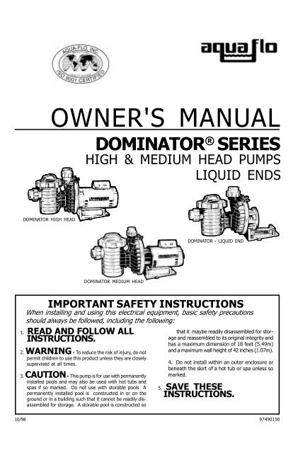
OWNER'S MANUAL<br />
DOMINATOR ® SERIES<br />
HIGH & MEDIUM HEAD PUMPS<br />
LIQUID ENDS<br />
DOMINATOR HIGH HEAD<br />
DOMINATOR - LIQUID END<br />
DOMINATOR MEDIUM HEAD<br />
IMPORTANT SAFETY INSTRUCTIONS<br />
When installing and using this electrical equipment, basic safety precautions<br />
should always be followed, including the following:<br />
1. READ AND FOLLOW ALL<br />
INSTRUCTIONS.<br />
2. WARNING - To reduce the risk of injury, do not<br />
permit children to use this product unless they are closely<br />
supervised at all times.<br />
3. CAUTION - This pump is for use with permanently<br />
installed pools and may also be used with hot tubs and<br />
spas if so marked. Do not use with storable pools A<br />
permanently installed pool is constructed in or on the<br />
ground or in a building such that it cannot be readily disassembled<br />
for storage. A storable pool is constructed so<br />
that it maybe readily disassembled for storage<br />
and reassembled to its original integrity and<br />
has a maximum dimension of 18 feet (5.49m)<br />
and a maximum wall height of 42 inches (1.07m).<br />
4. Do not install within an outer enclosure or<br />
beneath the skirt of a hot tub or spa unless so<br />
marked.<br />
5. SAVE THESE<br />
INSTRUCTIONS.<br />
10/98 97490150
INSTALLATION & OPERATING INSTRUCTIONS<br />
GENERAL<br />
Your AQUA-FLO pump has been quality built and engineered to<br />
give maximum efficiency under normal water pumping conditions.<br />
Consult the manufacturer for any other applications.<br />
INSTALLATION<br />
I. LOCATION OF PUMP<br />
Place pump on a firm level surface. Pump need not be bolted<br />
down unless required by local code. Select a location close to<br />
the filter allowing for convenience and serviceability.<br />
II. PUMP CONNECTIONS<br />
Suction line from pool (skimmer and main drain) must be connected<br />
to inlet at hair and lint trap. It is recommended to have a<br />
minimum of 12" of straight pipe before hair and lint trap. Discharge<br />
line to pool (return lines) must be connected to outlet at<br />
top of pump via filter. If pump is installed below water level of<br />
pool, install valves on the inlet and outlet piping to permit removing<br />
of equipment without draining the pool.<br />
CAUTION: During the pressure test procedure, this pump is under<br />
pressure. DO NOT LOOSEN “V” clamp or trap lock ring while<br />
pump is running or until all pressure is released. Tighten lock<br />
ring securely by hand only. Raise pressure slowly. Do not exceed<br />
35 psi. Extreme care must be taken during pressure test.<br />
Failure to follow these instructions explicitly can result in personal<br />
injury.<br />
OPERATION<br />
I. PRIMING PUMP<br />
At initial start-up, pump must be primed by filling hair and lint trap<br />
with water. To prime pump, remove cover from hair and lint trap:<br />
fill pump and suction trap with water. Replace cover (make sure<br />
the O-ring is in place) and tighten lock ring. Pump will now prime,<br />
with priming time depending upon lift and horizontal distance of<br />
suction piping.<br />
II. CLEANING BASKET<br />
It is important to clean the hair and lint basket frequently. A dirty<br />
basket will reduce the efficiency of the filter and heater and will<br />
put an abnormal stress on the pump motor which could result in<br />
costly repair bills.<br />
CAUTION: Do not remove hair and lint strainer lid while pump is<br />
running or under pressure! Lid is held in place by a lock ring<br />
which can be removed or tightened by hand. Basket must be<br />
kept clear of leaves and debris at all times.<br />
III. REMOVING BASKET<br />
1.) Turn off motor. 2.) Remove lock ring by rotating counter clockwise.<br />
DO NOT USE TOOLS. 3.) Remove lid. 4.) Remove basket<br />
and empty debris. 5.) Replace basket, fill with water, replace lid<br />
WARNING - All electrical wiring of the motor installation must be done by a qualified electrician in accordance with applicable<br />
electrical codes. Before working on any motor be certain that the source of electrical power is off at the main junction box.<br />
BONDING WIRE - Upon installation of the pump, the motor must be bonded with a No. 8 AWG (8.4mm 2 ) solid copper conductor<br />
per National Electric Code. The connection should be from the accessible wire connector on the motor to all metal parts of<br />
the swimming pool, spa, or hot tub structure and to all electrical equipment, metal conduit, and metal piping within 5 feet<br />
(1.5m) of the inside walls of a swimming pool, spa or hot tub, when the motor is installed within 5 feet of the inside walls of the<br />
swimming pool, spa, or hot tub.<br />
NOTE: For electrical connections, see wiring diagram on motor rating plate.<br />
If pump looses prime, or if too many bubbles come through<br />
return line, check:<br />
1.) Hair and lint pot cover is tight and O-ring is in place and free<br />
from defects.<br />
2.) Valves on suction and return lines are working properly and<br />
open.<br />
3.) Water level in pool is too low.<br />
4.) Filter O-ring or gasket is in place and free from defects.<br />
5.) All fittings and connections are secure and air tight.<br />
Not pumping water, check:<br />
1.) Filter pressure gauge reading too high, indicating filter needs<br />
cleaning.<br />
2.) Clogged plumbing lines.<br />
3.) Clogged impeller.<br />
4.) Worn or damaged impeller.<br />
Motor does not run, check:<br />
1.) Circuit Breakers.<br />
2.) Incorrect or loose wire connections<br />
and lock ring securely to prevent air from entering and tighten. DO<br />
NOT USE TOOLS. 6.) Turn on motor. 7.) Open air-relief valve on<br />
top of filter until steady stream of water comes out.<br />
NOTE: If pump is installed below water level of pool, close return<br />
and suction lines prior to opening hair and lint pot. Make sure to<br />
re-open valves prior to operating.<br />
DO NOT RUN PUMP DRY!<br />
Always maintain proper water level in pool. If water level falls<br />
below skimmer intake, pump will suck air. Pump is equipped with<br />
a maintenance-free heavy-duty mechanical seal. Damage will occur<br />
if pump runs dry, and warranty will be voided.<br />
IV. TO PREVENT FREEZING<br />
Drain liquid from pump through plug at bottom front section of volute.<br />
It is recommended to apply a good rust inhibitor into liquid<br />
end to prevent corrosion. Be sure motor is kept dry and covered.<br />
In mild climate area, when freezing may occur, run pump and filter<br />
equipment continuously to prevent freezing.<br />
MOTOR<br />
Your pump is equipped with a permanently lubricated, maintenance-<br />
free, heavy-duty industrial quality motor especially designed<br />
to withstand the heavy-duty requirements of swimming pool application.<br />
Wiring connection must agree with incoming line voltage.<br />
Improper wiring can cause serious injuries and damage to the<br />
motor, voiding warranty. (For wiring instructions, see diagram on<br />
motor rating plate.)<br />
NOTE: Motor is designed to withstand the effects of normal rainfall.<br />
To increase the life of your motor observe the following:<br />
1.) Do not flood motor or submerge in water. To do so voids<br />
warranty.<br />
2.) Provide ample cross ventilation, minimum of 6" at all points.<br />
3.) Keep motor and surrounding area clean.<br />
4.) Avoid sweeping or stirring dust near motor while it is running.<br />
5.) Avoid storing or spilling dry chemicals, powders, etc., near<br />
motor.<br />
6.) Provide protection against the elements.<br />
7.) Locate motor on a slight elevation so water will drain away<br />
from motor.<br />
8.) Avoid spilling or dripping liquid chemicals on or near motor.<br />
9.) Avoid splashing water or hosing deck near motor. Water damage<br />
voids warranty.<br />
TROUBLE SHOOTING<br />
For replacements contact your local supplier or authorized serviceman.<br />
3.) Thermal protector in motor tripped. Allow motor to cool, then<br />
try to restart.<br />
Motor makes humming noise but won’t start, check:<br />
1.) Make sure motor shaft turns free.<br />
2.) Jammed impeller or an obstruction in (volute) casing.<br />
3.) Low voltage and undersized wire.<br />
Motor overheating and cycling on and off, check:<br />
1.) Incorrect or loose wire connections.<br />
2.) Low voltage supply (frequently caused by undersized wire).<br />
3.) Make sure the motor gets a fresh air supply and the vents are<br />
kept unclogged.<br />
Noises, check:<br />
1.) Plumbing vibration.<br />
2.) Impeller turns freely and is properly adjusted.<br />
3.) Motor bearings.<br />
4.) For cavitation, due to obstruction in or undersized suction<br />
line.
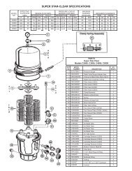
DOMINATOR ® HIGH HEAD REPLACEMENT PARTS<br />
REF<br />
NO.<br />
1<br />
2<br />
3<br />
4<br />
5<br />
6<br />
7†<br />
8<br />
8<br />
8<br />
8<br />
8<br />
9<br />
10<br />
11<br />
12<br />
13<br />
14<br />
15<br />
PART NO.<br />
99050250<br />
99050300<br />
99890000<br />
91100150<br />
92280003<br />
92500150<br />
91692400<br />
91692450<br />
91692500<br />
91692550<br />
91692600<br />
99730150<br />
91270002<br />
92200140<br />
99730060<br />
92200180<br />
99100020<br />
91200003<br />
DESCRIPTION<br />
Motor, Square Flange<br />
Bolt, Hex Machine, 3/8"-16 x 1"<br />
Bolt, Hex Machine, 3/8"-16 x 1-1/2<br />
Washer, Flat 3/8"<br />
Base<br />
Plate, Seal, “200 Seal<br />
Seal, Replacement, “200” Seal<br />
Impeller, .50 HP, High Head<br />
Impeller, .75 HP, High Head<br />
Impeller, 1.0 HP, High Head<br />
Impeller, 1.5 HP, High Head<br />
Impeller, 2.0 HP, High Head<br />
Screw, 1/4"-20 x 11/16"<br />
Diffuser<br />
O-ring, Metric<br />
Screw, 8/32" x 3/4" Phillips Pan Head<br />
O-ring, #449<br />
Clamp, V “D” Series, w/knob<br />
Casing<br />
† 92500050 Seal, Replacement, #1000 on models prior to 1995<br />
QTY.<br />
——<br />
4<br />
2<br />
2<br />
1<br />
4<br />
1<br />
1<br />
1<br />
1<br />
1<br />
1<br />
1<br />
1<br />
1<br />
3<br />
1<br />
1<br />
1<br />
REF<br />
NO.<br />
16<br />
17<br />
18<br />
19<br />
20<br />
21<br />
22<br />
23<br />
24<br />
25<br />
26<br />
27<br />
28<br />
29<br />
Q<br />
QQ<br />
PART NO.<br />
92200060<br />
92290020<br />
91920050<br />
91230300<br />
92200190<br />
91110040<br />
92620552<br />
91450210<br />
99050000<br />
92200100<br />
52203000<br />
52202000<br />
91431150<br />
91431250<br />
91431200<br />
92200210<br />
91431200<br />
91040250<br />
DESCRIPTION<br />
O-ring, #111<br />
Plug, Pipe, Wing<br />
Lock Ring, Trap<br />
Cover, Trap<br />
O’Ring, Trap Lid, #254<br />
Basket, Strainer, 6", “D” Series<br />
Trap, 6" x 2"<br />
Flange, Suction 2"<br />
Bolt, Hex Machine, 3/8"-16 x 3/4"<br />
O-ring, #229<br />
Fitting, Compression Comp., 2" x 1/2"<br />
Fitting, Compression Comp., 2"<br />
Fitting, Union Nut, 2"<br />
Fitting, Tail Peice, 2" x 1-1/2"<br />
Fitting, Tail Peice, 2" x 2"<br />
O-ring, #230<br />
Fitting, Tail Piece, 2"<br />
Assembly, Trap Complete, 6" x 2"<br />
Q Not shown<br />
Q Q Includes Ref. Items 18-22 & 24<br />
QTY.<br />
1<br />
1<br />
1<br />
1<br />
1<br />
1<br />
1<br />
1<br />
2<br />
1<br />
2<br />
2<br />
2<br />
2<br />
2<br />
1
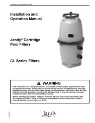
DOMINATOR ® MEDIUM HEAD REPLACEMENT PARTS<br />
REF<br />
NO.<br />
1<br />
2<br />
3<br />
4<br />
5<br />
6<br />
7<br />
8<br />
† 9<br />
10<br />
‡11<br />
12<br />
12<br />
12<br />
12<br />
12<br />
13<br />
PART NO. DESCRIPTION QTY. REF<br />
PART NO. DESCRIPTION<br />
NO.<br />
99050250<br />
99050300<br />
99890000<br />
91100150<br />
91140351<br />
99050000<br />
99730000<br />
92520040<br />
92280003<br />
92500150<br />
91692405<br />
91692455<br />
91692505<br />
91692555<br />
91692605<br />
56910070<br />
14 92200250<br />
14A 92200100<br />
15 99730550<br />
Motor, “C” Face, Keyed Shaft<br />
Bolt, Hex Machine, 3/8"-16 x 1"<br />
Bolt, Hex Machine, 3/8"-16 x 1-1/2<br />
Washer, Flat 3/8"<br />
Base<br />
Bracket, “200” Seal<br />
Bolt, Hex Machine, 3/8" - 16 x 3/4"<br />
Screw, Socket Set 1/4" - 20 x 5/16"<br />
Shaft, Extension, “200” Seal<br />
Plate, Seal, “200” Seal<br />
Seal, Replacement, “200” Seal<br />
Impeller, .50 HP, Medium Head<br />
Impeller, .75 HP, Medium Head<br />
Impeller, 1.0 HP, Medium Head<br />
Impeller, 1.5 HP, Medium Head<br />
Impeller, 2.0 HP, Medium Head<br />
Diffuser Assembly:<br />
§<br />
13A - Diffuser - 91270020<br />
§<br />
13B - Wear Ring - 92830051<br />
O-ring, #232<br />
O-ring, #229<br />
Screw, 8/32" x 1" Phillips Pan Head<br />
Q Not Shown<br />
† Use 92520010 - Shaft Extension for # 1000 seal<br />
‡ 92500072 - Seal, Replacement, #1000 on models prior to 1995<br />
§ Not available separately<br />
——<br />
6<br />
2<br />
2<br />
1<br />
1<br />
4<br />
3<br />
1<br />
1<br />
1<br />
1<br />
1<br />
1<br />
1<br />
1<br />
1<br />
1<br />
1<br />
1<br />
1<br />
3<br />
16<br />
17<br />
18<br />
19<br />
20<br />
21<br />
22<br />
23<br />
24<br />
25<br />
26<br />
27<br />
28<br />
29<br />
30<br />
31<br />
Q<br />
Q<br />
Q<br />
32<br />
33<br />
92200180<br />
99100020<br />
91200003<br />
99730160<br />
92200060<br />
92290020<br />
91920050<br />
91230300<br />
92200190<br />
91110040<br />
92620552<br />
91450210<br />
52203000<br />
52202000<br />
92200210<br />
91431250<br />
91431200<br />
91431150<br />
52202000<br />
91431200<br />
91040250<br />
92520030<br />
92530040<br />
O-ring, #449<br />
Clamp, V, “D” Series, w/knob<br />
Casing, “D” Series<br />
Screw, 1/4"-20 x 1/2", LH, RD, HD<br />
O-ring, #111<br />
Plug, Pipe, Wing<br />
Lock Ring, Trap<br />
Cover, Trap<br />
O-ring, Trap Lid, #254<br />
Basket, Strainer, 6", “D” Series<br />
Trap, 6" x 2"<br />
Flange, Suction 2"<br />
Fitting, Compression Comp., 2" x 1-1/2"<br />
Fitting, Compression Comp., 2" x 2"<br />
O-ring, #230<br />
Fitting, Tail Piece, 2" x 1-1/2"<br />
Fitting, Tail Piece, 2"<br />
Fitting, Union Nut, 2"<br />
Fitting, Compression Comp., 2" x 2"<br />
Fitting, Tail Piece, 2"<br />
Assembly, Trap Complete 6" x 2",<br />
Extension Shaft, Shorty (Liquid End only)<br />
Spacer, Shorty Extension Shaft<br />
(Liquid End only)<br />
QTY.<br />
1<br />
1<br />
1<br />
1<br />
1<br />
1<br />
1<br />
1<br />
1<br />
1<br />
1<br />
1<br />
2<br />
2<br />
2<br />
2<br />
2<br />
2<br />
2<br />
1<br />
1<br />
1<br />
1<br />
A<br />
NOTE: Liquid End Only, used with "C" Face threaded shaft<br />
motor. The spacer is required with the original "Shorty"<br />
Shaft Extension and the "200" Series seal configuration.
DOMINATOR ® ASSEMBLY INSTRUCTIONS<br />
(Mounting Liquid End to Motor)<br />
To facilitate the assembly of the pump and make your installation easier,<br />
please read and follow these instructions:<br />
1.) Remove the liquid end and motor from their shipping<br />
cartons and check for any possible freight damage.<br />
2.) Set the motor base in place aligning the two slots<br />
with the bottom mounting holes in the motor bracket.<br />
Secure to the motor bracket and seal plate using the<br />
3/8-16 bolts that are supplied with the liquid end.<br />
3.) Place the liquid end and motor on a flat working<br />
surface to assist in the assembly of the complete unit.<br />
4.) If a “C” face motor is used, discard the shaft key.<br />
The key will not be required.<br />
NOTE: If a square flange threaded shaft motor is used,<br />
the pump bracket and the brass extension shaft supplied<br />
with your liquid end will not be used. Remove<br />
and set aside.<br />
5.) To facilitate and assure that the liquid end and motor<br />
are properly assembled, it is recommended that the<br />
trap and casing, as a unit, be removed by unscrewing<br />
and removing clamp band. For Square Flange assembly,<br />
proceed to step #7.<br />
6.) “C” FACE MOTOR ASSEMBLY:<br />
Place the motor on the pump base and insert the motor<br />
shaft into the brass extension shaft making sure the<br />
motor shaft keyway is in alignment with the set screws<br />
in the brass extension shaft.<br />
Important: Before installing the brass extension shaft<br />
to the motor, remove all the setscrews and apply a small<br />
amount of thread locking compound (supplied) along<br />
each screw's thread. Reinstall the setscrews.<br />
a. Place the pump bracket up against the motor, align<br />
ing the holes in the bracket with the threaded holes<br />
in the motor. Install the four 3/8-16 hex head bolts,<br />
but do not tighten at this time.<br />
b. Secure the brass extension shaft to the motor shaft<br />
by pushing the impeller towards the motor as far as<br />
it will go, using the opening in the diffuser. Make<br />
sure the shaft extension does not move forward while<br />
set screws are being tightened.<br />
c. Make sure the round head screw in the impeller is<br />
secure. If tightening is required, hold the flat areas<br />
on the brass extension shaft with a suitable tool, and<br />
tighten the screw by turning counter-clockwise.<br />
d. Now, tighten the four hex head bolts that secure the<br />
pump bracket to the motor. Also make sure that the<br />
four bolts securing the bracket and motor base to<br />
the seal plate are tight.<br />
Proceed to step #8.<br />
7.) SQUARE FLANGE MOTOR ASSEMBLY:<br />
Remove the diffuser and impeller. NOTE: The floating<br />
brass wear ring around the impeller hub. Place the<br />
motor on the pump base, inserting the motor shaft<br />
through the seal plate. Secure motor to seal plate using<br />
four 3/8-16 bolts.<br />
NOTE: Use the two longer bolts for securing of the<br />
motor base.<br />
a. Making sure the mechanical seal is properly in place,<br />
screw the impeller securely to the motor shaft. Se<br />
cure the round head slotted screw by tightening<br />
counter-clockwise.<br />
Proceed to step #8.<br />
8.) Make sure the floating brass wear ring is placed<br />
back in position around the impeller hub.<br />
9.) Place the diffuser back into position over the impeller<br />
and secure to the seal plate with the three #8-32<br />
screws.<br />
10.) Important: Before replacing the casing and trap,<br />
reach in with a couple of fingers and rotate the impeller,<br />
making sure it is clear and turning freely.<br />
11.) Place the casing and trap in position, making sure<br />
the discharge port connection is in a straight vertical<br />
position. Set the clamp band in place and tighten.<br />
12.) The pump is now ready to be installed.<br />
Replacement parts for <strong>Dominator</strong> ® liquid end are the same as <strong>Dominator</strong> ®<br />
Medium Head pump replacement parts except where noted. Please refer to<br />
<strong>Dominator</strong> ® Medium Head replacement parts page.
DOMINATOR ® SERIES PUMPS LIMITED WARRANTY<br />
Aqua-Flo, Inc.<br />
WARRANTS TO:<br />
_______________________________________________<br />
________________________________________________________________________________________________<br />
the original retail purchaser only, that the products they<br />
manufacture are free from defects in material and/or<br />
workmanship for a period of five years (pump seals warranty<br />
for 30 days) from date of purchase. If within the first two<br />
years, any such products shall prove defective, it shall be<br />
repaired or replaced at AQUA-FLO’S option as follows:<br />
The original retail purchaser shall first contact the installing<br />
dealer, as soon as possible after discovery of the defect,<br />
but in no event later that the expiration date of this warranty.<br />
Or upon notification,<br />
AQUA-FLO, INC.<br />
Customer Service Department<br />
P.O. Box 2526, Chino, CA 91708<br />
will advise the consumer of the address to which the<br />
defective item may be shipped, together with the model<br />
number, serial number and date of purchase of item claimed<br />
to be defective. The consumer must pay for all shipping<br />
charges.<br />
If within the years three through five any such products<br />
shall prove defective, the original retail purchaser shall be<br />
entitled to purchase replacement equipment or components<br />
at the following percentage off the current published list<br />
price:<br />
EXCLUSIONS<br />
1. This warranty shall not apply to any failures resulting<br />
from negligence, abuse, misuse, misapplication,<br />
improper installation, alteration or modification,<br />
chemical corrosion, or improper maintenance.<br />
2. Any items manufactured by other companies and used<br />
by AQUA-FLO in its products may carry warranties by<br />
the original manufacturers.<br />
3. AQUA-FLO is not liable for incidental or consequential<br />
damages, loss of time, inconvenience, incidental<br />
expenses, labor or material charges in connection with<br />
removal or replacement of the equipment.<br />
AQUA-FLO is not responsible for any implied warranties<br />
or representations by others, and the foregoing warranty<br />
is exclusive and in lieu of all warranties provided herein.<br />
Some states do not allow the exclusion or limitation of<br />
incidental or consequential damages, so the above<br />
limitation or exclusion may not apply to you.<br />
This warranty gives you specific legal rights, and you may<br />
also have other rights which vary from state to state.<br />
Third year 60%<br />
Fourth year 40%<br />
Fifth year 20%<br />
PUMPS FOR THE LEISURE WATER INDUSTRY<br />
. Box 2526 / Chino, CA 91710<br />
Shipping: 5651 Schaefer Ave. / Chino, CA 91710<br />
FAX: 909/627-5660 n TEL: 909/591-7453