Convention Paper - Menno van der Veen
Convention Paper - Menno van der Veen
Convention Paper - Menno van der Veen

Create successful ePaper yourself
Turn your PDF publications into a flip-book with our unique Google optimized e-Paper software.
<strong>Menno</strong> <strong>van</strong> <strong>der</strong> <strong>Veen</strong><br />
Signal weakening in audio transformers<br />
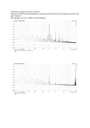
factor distortion). See figure-1 which demonstrates<br />
this effect.<br />
figure 2: Equivalent circuit of valve amp driving<br />
the loudspeaker Zs and Lp.<br />
figure 1: Dynamic Damping Factor Distortion<br />
where Zout (vertical axis) of a UL40 valve amp [11]<br />
depends on the output level and the frequency.<br />
For now I assume r i to be constant. If I would not<br />
do that, the real problem of this paper would not be<br />
recognizable anymore because of the abundant<br />
formulas. So, lets try to keep things simple.<br />
The secondary winding of the output transformer is<br />
loaded by a speaker Z s . I know that Z s is strongly<br />
frequency dependant, but for this study it is good<br />
enough to consi<strong>der</strong> Z s to be a constant.<br />
Also we can neglect the magnet wire resistances of<br />
the primary and secondary windings, because they<br />
represent constant losses, while I am researching<br />
variable losses caused by the core only. Let N p /N s<br />
be the turns ratio of the transformer. Then we can<br />
bring Z s to the primary side of the transformer by<br />
means of Z aa = Z s ⋅(N p /N s ) 2 .<br />
Figure 1 shows that for low frequencies below 1<br />
kHz the complete arrangement works as a voltage<br />
source driving the speaker AND the primary<br />
inductance L p of the primary winding. The current<br />
that flows through L p is called the exciting current<br />
I ex = v Lp /(2⋅π⋅f⋅L p ) and we wish that current to be<br />
as small as possible in or<strong>der</strong> to convert all audio<br />
music energy only to the loudspeaker. This means<br />
that L p should be as large as possible.<br />
The frequency and signal level dependant part of<br />
the transfer from the primary tubes to the<br />
loudspeaker is given by formula 1.<br />
s.Lp<br />
H(f) =<br />
r<br />
i<br />
// Z aa + s.Lp<br />
(1)<br />
The inductance of the primary winding is given by<br />
formula 2, where μ o is the magnetic permeability<br />
of vacuum; μ r is the relative magnetic permeability<br />
of the iron of the transformer core; N p is the total<br />
number of turns of the primary winding; l c is the<br />
magnetic path length inside the core; A is the cross<br />
sectional surface of the core; l g is the width of the<br />
gap. See for more information figure 3.<br />
μ .<br />
2<br />
N .<br />
0 p A<br />
L p ( 2)<br />
l c<br />
l g<br />
μ r<br />
The problem I studied results from the fact that the<br />
relative magnetic permeability of the core iron is<br />
not a constant, but depends strongly on the<br />
magnetic flux density inside the core, and thus<br />
from the level of the alternating voltage that the<br />
valves send to the transformer.<br />
AES 130th <strong>Convention</strong>, London, UK, 2011 May 13–16<br />
Page 2 of 8