Convention Paper - Menno van der Veen
Convention Paper - Menno van der Veen
Convention Paper - Menno van der Veen

You also want an ePaper? Increase the reach of your titles
YUMPU automatically turns print PDFs into web optimized ePapers that Google loves.
<strong>Menno</strong> <strong>van</strong> <strong>der</strong> <strong>Veen</strong><br />
Signal weakening in audio transformers<br />
The third line measures at 20 Hz and shows more<br />
clearly the loss of amplification caused by the<br />
perm behavior in the core.<br />
Notice that these three lines all have the same<br />
maximum, indicating a constant amplification (no<br />
influence of coupling capacitors) from 20 Hz to 1<br />
kHz.<br />
The fourth bottom line is measured at 10 Hz,<br />
clearly indicating perm collapse at low input levels<br />
and core saturation at high input levels, because<br />
the sloping down of the curve has shifted to the<br />
left.<br />
Noise residuals are visible below an input voltage<br />
of -80 dBV in the 20 and 10 Hz measurements,<br />
showing the reason why I had to limit the input<br />
voltage range for a reliable result.<br />
Combining formulas 1 to 3 with the perm<br />
measurements of figure 4 completely describes the<br />
behavior as shown in figure 8. The model<br />
presented in [8] and here is correct and its effects<br />
are noticeable in practical valve amplifiers.<br />
The 1 kHz line is straight with a small bulb at the<br />
right side because of overdrive of the tube<br />
circuitry. The 70 Hz line is little sloped, caused by<br />
perm-loss as discussed here. The 20 Hz line is<br />
further sloped and at the right side the transformer<br />
is just driven into saturation. The 10 Hz line shows<br />
this effect more pronounced.<br />
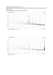
figure 9: example-2 of core collapse.<br />
From top to bottom: 1 kHz, 70 Hz, 20 Hz, 10 Hz.<br />
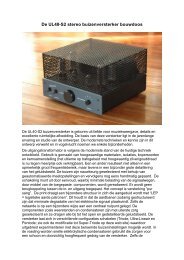
Amplifier "UL40-S2" [11] with Ultra Linear<br />
negative feedback<br />
The third example in figure 10 shows a multi<br />
paralleled power tube amplifier with very small<br />
effective plate resistance r i of the combined power<br />
tubes, resulting in little deviation of linearity. In<br />
this amplifier no auto-bias module was installed,<br />
bias shifting occurs on the right side. Only at 10<br />
Hz a little deviation of linearity is noticed plus core<br />
saturating at maximum output power.<br />
figure 8: example of core collapse.<br />
From top to bottom: 1 kHz, 70 Hz, 20 Hz, 10 Hz.<br />
Amplifier "GERT-RL12"; no internal negative<br />
feedback.<br />
The next example (figure 9) is an ultra linear<br />
negative feedback amplifier and internal<br />
electronics (auto-bias module, see [11] ) prevents<br />
bias shifting inside the amplifier, making more<br />
clear what happens inside the output transformer.<br />
The fourth and last example (see figure 11) is an<br />
amplifier with 13 dB overall negative feedback,<br />
[6],[7],[11]<br />
combined with local Super Triode<br />
feedback . Bias-shifting is prevented with an autobias<br />
module. It is clearly visible that the feedback<br />
has "cured" the deviations of linearity, and only for<br />
10 Hz the transformer core saturation is visible.<br />
AES 130th <strong>Convention</strong>, London, UK, 2011 May 13–16<br />
Page 6 of 8