View Installation/Operations Manual - Master-Bilt
View Installation/Operations Manual - Master-Bilt
View Installation/Operations Manual - Master-Bilt

Create successful ePaper yourself
Turn your PDF publications into a flip-book with our unique Google optimized e-Paper software.
____________________________________________________________<br />
BSD SERIES<br />
REFRIGERATORS AND FREEZERS<br />
<strong>Installation</strong>, Operation and<br />
Maintenance Instructions<br />
____________________________________________________________<br />
INSPECTION<br />
When the equipment is received, all items should be carefully checked against the bill of<br />
lading to insure all crates and cartons have been received. All units should be inspected<br />
for concealed damage by uncrating the units immediately. If any damage is found, it<br />
should be reported to the carrier at once, and a claim should be filed with the carrier. This<br />
equipment has been inspected and tested at the manufacturing facility and has been<br />
crated in accordance with transportation rules and guidelines. Manufacturer is not<br />
responsible for freight loss or damage.<br />
GENERAL<br />
INSTALLATION<br />
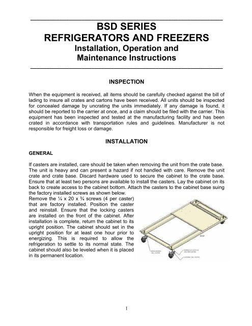
If casters are installed, care should be taken when removing the unit from the crate base.<br />
The unit is heavy and can present a hazard if not handled with care. Remove the unit<br />
crate and crate base. Discard hardware used to secure the cabinet to the crate base.<br />
Ensure that at least two persons are available to install the casters. Lay the cabinet on its<br />
back to create access to the cabinet bottom. Attach the casters to the cabinet base suing<br />
the factory installed screws as shown below.<br />
Remove the ¼ x 20 x ¾ screws (4 per caster)<br />
that are factory installed. Position the caster<br />
and reinstall. Ensure that the locking casters<br />
are installed on the front of the cabinet. After<br />
installation is complete, return the cabinet to its<br />
upright position. The cabinet should set in the<br />
upright position for at least one hour prior to<br />
energizing. This is required to allow the<br />
refrigeration to settle to its normal state. The<br />
cabinet should also be leveled when it is placed<br />
in its permanent location.<br />
1
If the doors are out of alignment on the cabinet, the doors can be adjusted. This can be<br />
accomplished by opening the door(s) and loosening the screws that hold both the top and<br />
bottom hinges to the cabinet. After adjusting the door so that it is aligned correctly,<br />
tighten the screws to securely hold the hinges in place.<br />
ELECTRICAL<br />
Check the proposed outlet to be used to insure that the voltage, phase and current<br />
carrying capacity of the circuit from the electrical panel correspond to the requirements of<br />
the cabinet. NEVER use an extension cord to wire any unit. On permanently connected<br />
units, those not furnished with a plug-in service cord, all inter-wiring between the<br />
electrical panel and the unit must be done in accordance with the National Electric Code<br />
and all state and local codes. Refer to the serial tag for all pertinent electrical information.<br />
Observe all Warning Labels. Disconnect power supply to eliminate injury from<br />
electrical shock or moving parts when servicing equipment.<br />
GENERAL OPERATION<br />
The refrigerators and freezers employ a unit cooler evaporator located outside the<br />
cabinet as the heat removing source. Through the refrigeration process, heat is captured<br />
in the evaporator, transferred to the condensing unit on top of the cabinet, and expelled<br />
to the surrounding outside air. It is extremely important to allow a four (4) inch clearance<br />
on the top, rear, and sides of the unit for the refrigeration process to function properly.<br />
These refrigerators and freezers utilize a programmable controller to control the<br />
temperature and defrost settings. The controller, which is located on the facade of<br />
the unit, is factory set. Please see the default settings sheet and separate<br />
instructions that are included on the operation of this controller.<br />
REFRIGERATORS<br />
During the operation of a refrigerator unit, frost will periodically form on the coil surface.<br />
Each time the compressor cycles "off", the evaporator fans will continue to run, which will<br />
keep the internal temperature uniform and at the same time remove any frost build up on<br />
the coil. The water produced will collect in the unit cooler drain pan and travel down the<br />
drain tube to the condensate vaporizer.<br />
FREEZERS<br />
After shutting the door on freezer models, a short amount of time must be allowed before<br />
the door can be reopened. This is due to the tight seal maintained between the door and<br />
the cabinet. Waiting a few moments for the pressure to equalize permits the door to be<br />
opened easily.<br />
A positive defrost is required to remove frost from the coil in freezer models. This is<br />
accomplished by energizing heaters during the defrost cycle that are positioned on the<br />
coil surface. The programmable controller is factory set to allow four defrosts per day.<br />
2
As the preset defrost time is reached, the controller automatically terminates the<br />
refrigeration process by turning off the condensing unit and unit cooler fan motors, and<br />
energizes the defrost heaters. As the coil temperature increases, the frost begins to melt<br />
producing water which runs down the coil to the unit cooler drain pan and exits through<br />
the drain tube to the vaporizer. After all the frost has been removed and the coil<br />
temperature reaches approximately 50°F [10ºC], the defrost is terminated through the<br />
action of the defrost termination control located on the unit cooler, and the refrigeration<br />
process resumes. In order to insure that any excess water remaining on the coil is not<br />
sprayed into the cabinet interior, and all heat generated by the defrost is removed, the<br />
unit cooler fans will not operate until the coil temperature reaches approximately<br />
25°F [-4ºC].<br />
PERIODIC CLEANING<br />
GENERAL MAINTENANCE<br />
Beginning with the initial installation, the interior surfaces of the cabinet should be<br />
periodically wiped down with a solution of warm water and baking soda. This solution will<br />
remove any odors from spillage that has occurred. The exterior of the cabinet should also<br />
be cleaned frequently with a commercial grade of glass cleaner.<br />
Monthly cleaning of the condenser will aid the heat transfer characteristics of the<br />
refrigeration system and increase its efficiency. To accomplish this, remove the cover<br />
panel from the cabinet and use a wire brush to loosen any dirt particles that are attached<br />
to the fins. Use a vacuum cleaner to remove the loosened particles. Failure to keep the<br />
condenser coil clean and clear of obstructions could result in temperature loss<br />
and damage to the compressor.<br />
All moving parts have been permanently lubricated and will generally require no<br />
maintenance.<br />
3
MAINTENANCE SERVICE AND ANALYSIS GUIDE<br />
REFRIGERATION SYSTEMS - ALL MODELS<br />
MALFUNCTION POSSIBLE CAUSE SOLUTION<br />
Compressor will not start - 1. Service cord unplugged 1. Plug in service cord<br />
no hum 2. Fuse blown or removed 2. Replace fuse<br />
3. Overload tripped 3. Determine reasons and correct<br />
4. Control stuck open 4. Repair or replace<br />
5. Wiring incorrect 5. Check wiring against the diagram<br />
Compressor will not start - 1. Improperly wired 1. Check wiring against the diagram<br />
hums but trips on overload 2. Low voltage to unit 2. Determine reason and correct<br />
protector 3. Starting capacitor defective 3. Determine reason and replace<br />
4. Relay failing to close 4. Determine reason, correct or replace<br />
Compressor starts and runs, 1. Low voltage to unit 1. Determine reason and correct<br />
but short cycles on overload 2. Overload defective 2. Check current, replace overload protector<br />
protector 3. Excessive head pressure 3. Check ventilation or restriction in<br />
refrigeration system 4. Compressor hot-return gas hot 4. Check refrigerant charge, fix leak if necessary<br />
Compressor operates long 1. Short of refrigerant 1. Fix leak, add charge<br />
or continuously 2. Control contact stuck 2. Repair or replace<br />
3. Evaporator coil iced 3. Determine cause, defrost manually<br />
4. Restriction in refrigeration system 4. Determine location and remove restriction<br />
5. Dirty condenser 5. Clean condenser<br />
Compressor runs fine, but 1. Overload protector 1. Check wiring diagram<br />
short cycles 2. Cold control 2. Differential too close - widen<br />
3. Overcharge 3. Reduce charge<br />
4. Air in system 4. Purge and recharge<br />
5. Undercharge 5. Fix leak, add refrigerant<br />
Starting capacitor open, 1. Relay contacts stuck 1. Clean contacts or replace relay<br />
shorted or blown 2. Low voltage to unit 2. Determine reason and correct<br />
3. Improper relay 3. Replace<br />
Relay defective or burned out 1. Incorrect relay 1. Check and replace<br />
2. Voltage too high or too low 2. Determine reason and correct<br />
Refrigerated space too warm 1. Control setting too high 1. Reset control<br />
2. Refrigerant overcharge 2. Purge refrigerant<br />
3. Dirty condenser 3. Clean condenser<br />
4. Evaporator coil iced 4. Determine reason and defrost<br />
5. Not operating 5. Determine reason, replace if necessary<br />
Standard temperature system 1. Control setting is too low 1. Reset the control<br />
freezes the product 2. Control points stuck 2. Replace the control<br />
Objectionable noise 1. Fan blade hitting fan shroud 1. Reform or cut away small section of shroud<br />
2. Tubing rattle 2. Locate and reform<br />
3. Vibrating fan blade 3. Replace fan blade<br />
4. Condenser fan motor rattles 4. Check motor bracket mounting, tighten<br />
5. General vibration 5. Compressor suspension bolts not loosened<br />
on applicable models - loosen them<br />
6. Worn fan motor bearings 6. Replace fan motor<br />
Pan Area 1. No cooling 1. Make sure switch is in the "on" position<br />
2. Too cold 2. Adjust temperature control - see instructions<br />
under pan area<br />
3. Too warm 3. Adjust temperature control - see instructions<br />
under pan area<br />
4
____________________________________________________________<br />
INSTRUCTIONS FOR REVERSING<br />
THE SWING OF SOLID DOORS<br />
____________________________________________________________<br />
Complete the following steps if reversing the swing of the solid door(s) is desired. These steps apply to both<br />
refrigerators and freezers.<br />
1. With a one, two, or three door model, first open the door and located the screws holding the hinges and door in<br />
position.<br />
2. Two people are recommended to make this change. One person should hold the door at a 90° angle to the cabinet<br />
while the other person removes the screws holding the door to the cabinet. The normal installation at the factory<br />
is to have the spring loaded door-closing mechanism located at the bottom of the cabinet. When removing the<br />
spring tension bracket from the cabinet bottom, be careful that it does not snap back. This may result in<br />
pinched fingers.<br />
3. After the door(s) are removed, remove the door lock strike(s) from the cabinet by removing the two mounting<br />
screws.<br />
4. Find the holes, drilled through the outer skin only, located on the opposite side of the door opening from where<br />
the hinges were previously located. Drill through the tapping plate found behind these holes using a 7/32" drill<br />
bit.<br />
5. Turn the door over and align it to the cabinet so it will swing in the desired direction. The spring loaded door<br />
closing hinge will now be located at the top of the reversed door. Mount the hinges to the cabinet using the holes<br />
that were drilled out in step 4, along with the previously removed screws. Check the door(s) to be certain that it is<br />
mounted squarely and that the gaskets seal properly around the door opening. The door can be adjusted by<br />
moving the top or bottom hinge slightly.<br />
6. The original hinge holes can be filled with silicone, or with 1/4-20x3/4 pan head stainless steel screws if desired.<br />
7. Locate the door lock strike by visually aligning it to the dead bolt lock in the door while the door is in the closed<br />
position. While holding the strike in position, mark the top, bottom, and edge of the strike on the cabinet wall or<br />
mullion with a pencil or fine point marker that will remain legible until completion of the task. Verify that the<br />
strike is positioned properly by assuring that it is aligned to the marks and hold it securely; open and close the<br />
door and extend and retract the dead bolt to make certain they clear without touching. The strike cannot be<br />
adjusted after it is mounted.<br />
8. Align the strike to the marks, which were made in step 7 and mark the centers of the holes for the mounting<br />
screws. Using a #20 drill bit, drill the holes you just marked approximately one-half inch deep. Take care not to<br />
puncture the interior side of the cabinet. Note: If a #20 bit is not available, use a 5/32" drill bit.<br />
9. Mount the door lock strike using the screws that were removed from the original position. The screws may have<br />
to be forced until the thread cutting tip has passed through the entire metal thickness. The original door strike<br />
holes can be filled with silicone, or with two 10-24x1/2 stainless steel pan head screws if desired.<br />
5
MASTER-BILT ELECTRONIC REFRIGERATION CONTROL<br />
Display Lay-out<br />
Compressor When power is first turned on to the control, the LED indicator for the Thermostat<br />
output will go through the start-up delay. After a one-minute delay the compressor comes on. The<br />
LED indicator stays on while compressor relay is energized. Display will show actual box<br />
temperature. Picture above is the display layout. The compressor will be cycled off when the<br />
actual box temperature reaches its set point. The Thermostat output indicator will be off.<br />
Fan The fans will run constantly for Refrigerators application, and off during a defrost for the<br />
Freezers application. The Evaporator fan will also cut off when the evaporator temp is above the<br />
fan stop temperature setting.<br />
When the Freezer is in defrost mode; the fan is off until the end of the defrost and the 2 minute<br />
drip time has passed. There is 2 minute delay after a defrost before the fan comes on. If the<br />
evaporator temperature is 25 o F or below the controller will override the fan delay. FAN LED<br />
indicator is on while FAN relay is energized.<br />
7
Defrost The control uses time defrost with 4 defrosts per day for the Freezers and off cycle<br />
defrost for the Refrigerators.<br />
The Freezers time defrost scheme can be re-set the for special applications. During defrost the<br />
display will show dEF and the defrost LED indicator on. The control begins timing the defrost<br />
when power is turned on. Four defrost per day means it will occur every 6 hours. To have<br />
defrost occur at 8am, 2pm, 8pm, and 2am then power up at one of these four times.<br />
MANUAL DEFROST<br />
Defrosting my also be induced manually by keeping the defrost button for 5 seconds. Once<br />
defrost has started, the defrost will go through a defrost and drip time pull down cycle.<br />
HOW TO CHANGE THE SETPOINT<br />
HOW TO CHANGE a parameter value<br />
ELECTRICAL CONNECTIONS<br />
The controller is provided with a phoenix push terminal block to connect cables with a cross<br />
section up to 2,5 mm 2 . Before connecting cables make sure the power supply complies with the<br />
control’s requirements. Separate the probe cables from the power supply cables, the outputs and<br />
the power connections. Do not exceed the maximum current allowed on each relay, in case of<br />
heavier loads use a suitable external relay or contactors.<br />
PROBE CONNECTIONS<br />
The probes shall be mounted with the bulb upwards to prevent damage due to casual liquid<br />
infiltration. It is recommended to place the thermostat probe at the warmest location of return air<br />
streams to correctly measure the average room temperature. Place the defrost termination probe<br />
among the evaporator fins in the coldest place, where most ice is formed, far from heaters or from<br />
the warmest place during defrost, to prevent premature defrost termination.<br />
8
BSD-A Series Freezer<br />
FACTORY’S<br />
DESCRIPTION<br />
SETTING<br />
SCL Temperature scale. ºF<br />
SPL Minimum limit for SP setting -10<br />
SPH Maximum limit for SP setting 32<br />
SP Setpoint (value to be maintained in the room) -5<br />
C-H Refrigerating (REF) or Heating (HEA) control mode REF<br />
HYS Thermostat differential 4<br />
CRT Compressor rest time. 1<br />
CT1 Thermostat output runs when T1 is faulty. 6<br />
CT2 Thermostat outputs stop when probe T1 is faulty. 4<br />
CSD Compressor stop delay after the door has been opened 5<br />
DFR Defrost frequency expressed in cycles / 24 hours. 4<br />
DLI Defrost end Temperature 55<br />
DTO Maximum defrost duration 30<br />
DTY Defrost Type: OFF, ELE, GAS ELE<br />
DRN Pause after defrost (evaporator drain down time) 1<br />
DDY Display during defrost. (DEF) 4<br />
FID Fans active during defrost. NO<br />
FDD Evaporator fan re-stat temperature after defrost. 30<br />
FTC OptimiSed fan control enabling. With FTC=NO then; FT1, FT2, FT3 = 0 NO<br />
FT1 Fan stop delay after compressor stop. See Fig.2. 0<br />
FT2 Timed fan stop. With FT2=0 the fans remain on all the time. 0<br />
FT3 Timed fan run. With FT3=0, and FT2>0, the fans remain off all the time. 0<br />
ATM Alarm threshold management: NON, ABS, REL. ABS<br />
ALA Low temperature alarm threshold (ALR=0) -35<br />
AHA High temperature alarm threshold. (AHR=0) 32<br />
ALR Low temperature alarm differential. With ALR=0 the low temperature alarm is excluded. -<br />
AHR High temperature alarm differential. With AHR=0 the high temperature alarm is excluded. -<br />
ATD Delay before alarm temperature warning. 30<br />
ADO Delay before door open alarm warning. 15<br />
ACC Condensor periodic cleaning. 0<br />
IISM Switchover mode to second parameter set NON<br />
IISL Minimum limit for IISP setting. -<br />
IISH Maximum limit for IISP setting. -<br />
IISP Setpoint in mode 2. -<br />
IIHY OFF/ON differential in mode 2. -<br />
IIFT Optimised fan control enabling in mode 2. -<br />
IIDF Defrost timer set to start a defrost in mode 2. -<br />
SB Stand-by button enabling NO<br />
DS Door switch input enabling (closed when door is closed) NO<br />
LSM Light control mode NON<br />
OAU AUX output operation. DEF<br />
INP Temperature sensor selection. SN4<br />
OS1 Probe T1 offset. 0<br />
T2 Probe T2 enabling (Evaporator). NO<br />
OS2 Probe T2 offset. 0<br />
TLD Delay for minimum temperature (TLO) and maximum temperature (THI) logging 5<br />
SIM Display slowdown 0<br />
ADR AT2-5 address for PC communication. 1<br />
PARM*<br />
9
BSD-A Series Refrigerator<br />
FACTORY’S<br />
DESCRIPTION<br />
SETTING<br />
SCL Temperature scale. ºF<br />
SPL Minimum limit for SP setting 32<br />
SPH Maximum limit for SP setting 65<br />
SP Setpoint (value to be maintained in the room) 35<br />
C-H Refrigerating (REF) or Heating (HEA) control mode REF<br />
HYS Thermostat differential 4<br />
CRT Compressor rest time. 1<br />
CT1 Thermostat output runs when T1 is faulty. 6<br />
CT2 Thermostat outputs stop when probe T1 is faulty. 4<br />
CSD Compressor stop delay after the door has been opened 5<br />
DFR Defrost frequency expressed in cycles / 24 hours. 2<br />
DLI Defrost end Temperature 45<br />
DTO Maximum defrost duration 20<br />
DTY Defrost Type: OFF, ELE, GAS OFF<br />
DRN Pause after defrost (evaporator drain down time) 1<br />
DDY Display during defrost. (DEF) 3<br />
FID Fans active during defrost. YES<br />
FDD Evaporator fan re-stat temperature after defrost. 75<br />
FTC OptimiSed fan control enabling. With FTC=NO then; FT1, FT2, FT3 = 0 NO<br />
FT1 Fan stop delay after compressor stop. See Fig.2. 0<br />
FT2 Timed fan stop. With FT2=0 the fans remain on all the time. 0<br />
FT3 Timed fan run. With FT3=0, and FT2>0, the fans remain off all the time. 0<br />
ATM Alarm threshold management: NON, ABS, REL. ABS<br />
ALA Low temperature alarm threshold (ALR=0) 0<br />
AHA High temperature alarm threshold. (AHR=0) 55<br />
ALR Low temperature alarm differential. With ALR=0 the low temperature alarm is excluded. -<br />
AHR High temperature alarm differential. With AHR=0 the high temperature alarm is excluded. -<br />
ATD Delay before alarm temperature warning. 30<br />
ADO Delay before door open alarm warning. 15<br />
ACC Condensor periodic cleaning. 0<br />
IISM Switchover mode to second parameter set NON<br />
IISL Minimum limit for IISP setting. -<br />
IISH Maximum limit for IISP setting. -<br />
IISP Setpoint in mode 2. -<br />
IIHY OFF/ON differential in mode 2. -<br />
IIFT Optimised fan control enabling in mode 2. -<br />
IIDF Defrost timer set to start a defrost in mode 2. -<br />
SB Stand-by button enabling NO<br />
DS Door switch input enabling (closed when door is closed) NO<br />
LSM Light control mode NON<br />
OAU AUX output operation. DEF<br />
INP Temperature sensor selection. SN4<br />
OS1 Probe T1 offset. 0<br />
T2 Probe T2 enabling (Evaporator). YES<br />
OS2 Probe T2 offset. 0<br />
TLD Delay for minimum temperature (TLO) and maximum temperature (THI) logging 5<br />
SIM Display slowdown 0<br />
ADR AT2-5 address for PC communication. 1<br />
PARM*<br />
10