DA 1855A - Operator's Manual - Teledyne LeCroy
DA 1855A - Operator's Manual - Teledyne LeCroy
DA 1855A - Operator's Manual - Teledyne LeCroy

Create successful ePaper yourself
Turn your PDF publications into a flip-book with our unique Google optimized e-Paper software.
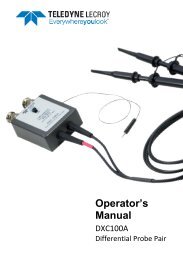
Operator’s <strong>Manual</strong><br />
Optional Accessories<br />
• Service <strong>Manual</strong>, containing adjustments, repair and replacement part information P/N:<br />
<strong>DA</strong><strong>1855A</strong>-SM-E.<br />
• DXC100A, ÷10 / ÷100 Passive Differential Probe.<br />
• DXC200, ÷1 Passive Differential Probe.<br />
• DXC5100, ÷100 2.5 K Passive Differential Probe Pair<br />
• <strong>DA</strong>101, External ÷10 Attenuator.<br />
Operation<br />
General Information<br />
The <strong>DA</strong><strong>1855A</strong> has been designed to be used with oscilloscopes equipped with a ProBus interface.<br />
Connecting the Differential Amplifier to the oscilloscope through the ProBus interface will<br />
automatically control all the required settings from the oscilloscope and will lock-out the <strong>DA</strong><strong>1855A</strong><br />
front panel controls. All front panel controls are now accessible through the oscilloscope user<br />
interface. The <strong>DA</strong><strong>1855A</strong> user interface can be viewed from the Channel setup dialog for the channel<br />
to which it is connected. The <strong>DA</strong><strong>1855A</strong> front panel controls will operate manually when the<br />
Differential Amplifier is connected to an oscilloscope not provided with a ProBus interface.<br />
NOTE: Removing the ProBus interface cable with the differential amplifier still powered up, requires<br />
the <strong>DA</strong><strong>1855A</strong> to be turned OFF and ON to access the front panel controls.<br />
Dynamic Range<br />
The basic amplifier dynamic range in X1 Gain and ÷1 Attenuation is ± 0.500 V. Changing the gain and<br />
or attenuation will affect both the Differential Mode and Common Mode ranges.<br />
The Differential Mode range is scaled by both gain and attenuation, while the Common Mode range<br />
is scaled by attenuation only.<br />
Gain<br />
Atten*<br />
Differential<br />
Mode*<br />
Common Mode*<br />
1 ÷1 ± 0.5 V ± 15.5 V<br />
1 ÷10 ± 5.0 V ± 155 V<br />
10 ÷1 ± 50 mV ± 15.5 V<br />
10 ÷10 ± 0.5 V ± 155 V<br />
* Attenuation, Common Mode and Differential Mode ranges are scaled with external probe attenuation. A ÷10<br />
probe will increase all these values by a factor of 10.<br />
922258-00 Rev A 11