DA 1855A - Operator's Manual - Teledyne LeCroy
DA 1855A - Operator's Manual - Teledyne LeCroy
DA 1855A - Operator's Manual - Teledyne LeCroy

You also want an ePaper? Increase the reach of your titles
YUMPU automatically turns print PDFs into web optimized ePapers that Google loves.
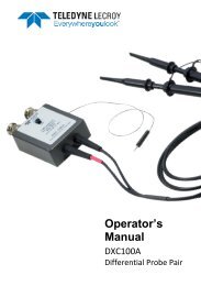
Operator’s <strong>Manual</strong><br />
Rejecting the AC line voltage was no real challenge, but rejecting the drain to source signal is a real<br />
measure of system ability. The drain to source voltage rises over 245 Volt when the FET turns OFF.<br />
The maximum rate of rise of this signal is about 15 V/nsec followed by a ring at the bottom of the<br />
waveform. It will be necessary to adequately reject this signal if upper gate signal is the be<br />
measured accurately.<br />
Upper and Lower Gate Drive<br />
To examine the gate drive signal on the upper FET’s Q1, the –INPUT probe will be connected to the<br />
source of Q1 and the +INPUT probe to the gate of Q1. The XC100 probes are set for an attenuation<br />
of ÷100 and the <strong>DA</strong><strong>1855A</strong> for an attenuation of ÷1 and a gain of X1. The EFFECTIVE GAIN indicator<br />
should read an overall gain of ÷100. To make room for other traces, the OFFSET control on the<br />
oscilloscope was set to –5.0 Volt, moving the trace up one division.<br />
The same procedure is repeated for Q2 gate drive where the OFFSET is set to +15 V to move the<br />
trace down by 3 divisions. By setting mVOLT/DIV to a more sensitive setting, small details of these<br />
signals can be examined.<br />
Avoiding Measurement Errors<br />
The math capabilities in modern digital oscilloscopes can save time and effort. Both scalar<br />
measurements and waveform math provide direct answers for measurements that used to require<br />
considerable computation and analysis. Common causes of erroneous results are:<br />
• Errors in conditioning the input signal, such as clipping or bandwidth limiting.<br />
• Limitation in the acquisition process, such as sample rate, resolution and record length.<br />
• Limitation in the computational algorithms.<br />
The most common source of error in power measurements results from the time delay (skew)<br />
between the voltage and current waveforms. The propagation delay through the current probe and<br />
the voltage probe plus differential amplifier are almost never equal. To eliminate resulting error in<br />
power waveforms, it is necessary to deskew the input signals. Some oscilloscopes have a deskew<br />
function that can be used to shift the time reference of one of the waveforms relative to the other.<br />
Another error to be concerned with is the phase shift in the probes or instrument. As the rise time<br />
of the input signal approaches the rise time of the current probe or amplifier, the phase shift will<br />
create an amplitude error in the power waveform.<br />
922258-00 Rev A 45