DA 1855A - Operator's Manual - Teledyne LeCroy
DA 1855A - Operator's Manual - Teledyne LeCroy
DA 1855A - Operator's Manual - Teledyne LeCroy

You also want an ePaper? Increase the reach of your titles
YUMPU automatically turns print PDFs into web optimized ePapers that Google loves.
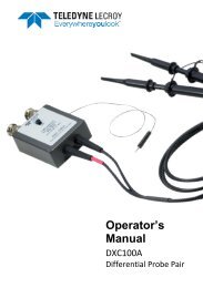
Operator’s <strong>Manual</strong><br />
compensation procedure can result in a significant decrease in the CMRR capability of any<br />
differential probe pair.<br />
It is a good practice to compensate a probe pair for a given amplifier and then leave the probe pair<br />
and amplifier together as a system. Similarly, it is important that, once compensated for given<br />
amplifier, each probe always be used on the same input (one probe always on the +INPUT and the<br />
other always on the –INPUT).<br />
DXC100A Differential Probe Pair<br />
The DXC100A is a high performance matched passive differential probe pair designed for use with<br />
<strong>Teledyne</strong> <strong>LeCroy</strong> <strong>DA</strong><strong>1855A</strong> series differential amplifiers. The probe pair consists of two well matched<br />
individual probes that share a common compensation box to allow the attenuation factor on both<br />
probes to be simultaneously switched between ÷10 and ÷100. When used with the <strong>DA</strong><strong>1855A</strong><br />
Differential Amplifier, the probe’s attenuation factor is automatically incorporated into the effective<br />
gain display and the decimal properly located in the Precision Voltage Generator (PVG) display.<br />
Probe Grounding<br />
The DXC100A Probe Pair is supplied with accessories that allow for three methods of connecting<br />
probe grounds.<br />
In most cases, when the common mode portion of the signal consists mainly of low frequencies (1<br />
MHz and below), the probe ground leads should not be connected to the ground of the circuit under<br />
test. They should be connected to each other. This minimizes the effects of ground loop currents.<br />
The signal corruption caused by not having the probes connected to the ground of the circuit under<br />
test will be common to both inputs and will be rejected by the differential amplifier.<br />
However, when working in an environment with high RF ambient noise, it is best to connect the<br />
probe ground leads to a good RF ground near the point where the signal is being measured.<br />
The best way to determine which probe grounding technique should be used is to try both methods<br />
and use the one that gives the least corruption of the differential signal.<br />
When adjusting the compensation and probe CMRR, the use of probe tip to BNC adapters is<br />
required. They provide the best performance of the three grounding method.<br />
General Operating Information<br />
This section will help you become familiar with the operation of the <strong>DA</strong><strong>1855A</strong> and how it interfaces<br />
with an oscilloscope. To carry out the following exercises, you will need an oscilloscope and a<br />
general purpose function generator.<br />
922258-00 Rev A 23