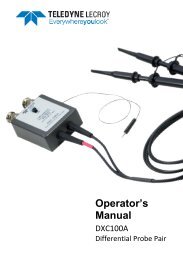
DA 1855A - Operator's Manual - Teledyne LeCroy
DA 1855A - Operator's Manual - Teledyne LeCroy
DA 1855A - Operator's Manual - Teledyne LeCroy
You also want an ePaper? Increase the reach of your titles
YUMPU automatically turns print PDFs into web optimized ePapers that Google loves.
Applications<br />
Operator’s <strong>Manual</strong><br />
Introduction<br />
Some parts of a power supply operation, such as saturation voltage, upper gate drive, loop response<br />
etc., have been difficult to perform without the proper accessories to expand the measurement<br />
capabilities of oscilloscopes. To obtain accurate voltage and current waveforms is a necessity before<br />
any waveform analysis can occur.<br />
Voltage Measurements<br />
A significant limitation in power supply characterization is that many of the signals of interest are<br />
referenced to voltages other than ground. Several techniques have been tried to overcome this<br />
measurement limitation.<br />
The most frequently used — and probably the worst one – is floating the oscilloscope by<br />
disconnecting the ground wire in the power-line cable. This allows the chassis of the oscilloscope to<br />
float to the potential to which the probe ground lead is connected. The most obvious danger is<br />
electrical shock. When an oscilloscope is floated to hazardous voltages, accidental contact with any<br />
metal component of the oscilloscope chassis can seriously injure or even kill the operator.<br />
Another problem when floating a scope is the inability to externally trigger the oscilloscope, or the<br />
waveform distortion that may occur when high slew rates appear on the ground lead. Another<br />
technique used for measuring voltages not referenced to ground is quasi-differential, or channel A<br />
minus Channel B. Even though this technique is safe, the oscilloscope is still grounded, it is still<br />
limited to measurements where the differential mode (signal of interest) is approximately the same<br />
amplitude or larger than the common mode signal (signal being rejected). A major problem however<br />
is the limited CMRR (Common Mode Rejection Ratio) caused by gain mismatches between the two<br />
input channels.<br />
The best solution for measuring voltages that are not referenced to ground is to use a differential<br />
amplifier. The <strong>DA</strong>1855 is ideally suited for these measurements.<br />
Measuring Current<br />
Current can be measured either by using a shunt resistor or by using a current probe. Adding a shunt<br />
resistor requires cutting the current carrying conductor. Shunt resistors will add a resistance to the<br />
circuit that can affect the operation. It is difficult to obtain accurate resistors with low resistance and<br />
low inductance values necessary to measure large dynamic currents.<br />
Current probes overcome these problems. Some models have a jaw that can be opened to install<br />
around conductors without the need to cut them. They come in two different types, AC and DC. The<br />
DC types can measure from DC to higher frequencies with relative flat frequency response. AC<br />
current probes have both a low frequency and a high frequency response. Many AC current probes<br />
922258-00 Rev A 39


