KX-TDA200 Getting Started - Panasonic
KX-TDA200 Getting Started - Panasonic
KX-TDA200 Getting Started - Panasonic
Create successful ePaper yourself
Turn your PDF publications into a flip-book with our unique Google optimized e-Paper software.
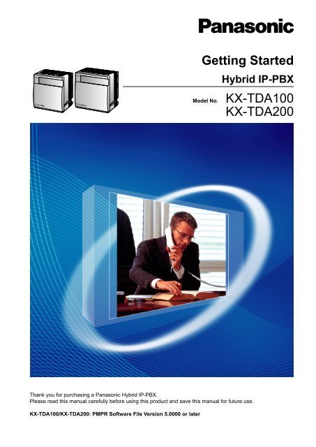
<strong>Getting</strong> <strong>Started</strong><br />
Model No.<br />
Hybrid IP-PBX<br />
<strong>KX</strong>-TDA100<br />
<strong>KX</strong>-<strong>TDA200</strong><br />
Thank you for purchasing a <strong>Panasonic</strong> Hybrid IP-PBX.<br />
Please read this manual carefully before using this product and save this manual for future use.<br />
<strong>KX</strong>-TDA100/<strong>KX</strong>-<strong>TDA200</strong>: PMPR Software File Version 5.0000 or later
Table of Contents<br />
Table of Contents<br />
1 Before Installation ....................................................................................3<br />
1.1 Safety Notices ...................................................................................................................4<br />
1.2 System Connection Diagram ...........................................................................................5<br />
1.3 Unpacking ..........................................................................................................................6<br />
2 Installation ................................................................................................9<br />
2.1 Opening/Closing the Front Cover ..................................................................................10<br />
2.2 Inserting the SD Memory Card to the MPR Card ..........................................................11<br />
2.3 Installing the Option Units .............................................................................................12<br />
2.4 Installing the Trunk Cards ..............................................................................................14<br />
2.5 Installing the Extension Cards (DLC8/DLC16/DHLC8/MSLC16/SLC8/SLC16/<br />
CSLC16) ...........................................................................................................................17<br />
2.6 Connecting Extensions ..................................................................................................17<br />
2.7 Frame Earth Connection ................................................................................................18<br />
3 Starting the PBX .....................................................................................19<br />
3.1 Starting the PBX ..............................................................................................................20<br />
4 Customising the PBX .............................................................................21<br />
4.1 Connecting the PC ..........................................................................................................22<br />
4.2 Installing the Maintenance Console ..............................................................................22<br />
4.3 Programming the PBX ....................................................................................................23<br />
5 Confirming the Connection ...................................................................29<br />
5.1 Making Calls ....................................................................................................................30<br />
2 <strong>Getting</strong> <strong>Started</strong>
Section 1<br />
Before Installation<br />
<strong>Getting</strong> <strong>Started</strong> 3
1.1 Safety Notices<br />
1.1 Safety Notices<br />
Please observe the safety notices in this manual in order to avoid danger to users or other people, and prevent<br />
damage to property.<br />
The notices are classified as follows, according to the severity of injury or damage:<br />
WARNING<br />
This notice means that misuse could result in death or serious injury.<br />
CAUTION<br />
This notice means that misuse could result in injury or damage to property.<br />
4 <strong>Getting</strong> <strong>Started</strong>
1.2 System Connection Diagram<br />
1.2 System Connection Diagram<br />
LCOT4<br />
(<strong>KX</strong>-TDA0183)<br />
DLC16<br />
(<strong>KX</strong>-TDA0172)<br />
DLC8<br />
(<strong>KX</strong>-TDA0171)<br />
for Digital Proprietary<br />
Telephone (DPT), DSS<br />
Console, and Portable<br />
Station (PS)<br />
<strong>KX</strong>-DT346/<strong>KX</strong>-DT343/<br />
<strong>KX</strong>-T7636/<strong>KX</strong>-T7633<br />
PC<br />
<strong>KX</strong>-DT300<br />
<strong>KX</strong>-T7600<br />
<strong>KX</strong>-DT300<br />
<strong>KX</strong>-T7600<br />
Telephone<br />
Company<br />
Private<br />
IP Network<br />
Batteries<br />
Station Message Detail<br />
Recording (SMDR)<br />
PC<br />
Analogue<br />
Trunk<br />
E & M Line<br />
ISDN BRI Line<br />
(Digital Trunk)<br />
ISDN PRI Line<br />
(Digital Trunk)<br />
T1 Line<br />
(Digital Trunk)<br />
E1 Line<br />
(Digital Trunk)<br />
Router<br />
LCOT16<br />
(<strong>KX</strong>-TDA0181)<br />
LCOT8<br />
(<strong>KX</strong>-TDA0180)<br />
CID/PAY8<br />
(<strong>KX</strong>-TDA0189)<br />
CID8<br />
(<strong>KX</strong>-TDA0193)<br />
DID8<br />
(<strong>KX</strong>-TDA0182)<br />
E&M8<br />
(<strong>KX</strong>-TDA0184)<br />
BRI4<br />
(<strong>KX</strong>-TDA0284)<br />
BRI8<br />
(<strong>KX</strong>-TDA0288)<br />
PRI30<br />
(<strong>KX</strong>-TDA0290CE/<br />
<strong>KX</strong>-TDA0290CJ)<br />
PRI23<br />
(<strong>KX</strong>-TDA0290)<br />
T1<br />
(<strong>KX</strong>-TDA0187)<br />
E1<br />
(<strong>KX</strong>-TDA0188)<br />
IP-GW4<br />
(<strong>KX</strong>-TDA0480)<br />
IP-GW4E<br />
(<strong>KX</strong>-TDA0484)<br />
IP-GW16<br />
(<strong>KX</strong>-TDA0490)<br />
PSU-S/<br />
PSU-M/<br />
PSU-L<br />
(<strong>KX</strong>-TDA0108/<br />
<strong>KX</strong>-TDA0104/<br />
<strong>KX</strong>-TDA0103)<br />
MPR<br />
(Installed by default)<br />
MEC<br />
(<strong>KX</strong>-TDA0105)<br />
CSLC16<br />
(<strong>KX</strong>-TDA0177)<br />
MSLC16<br />
(<strong>KX</strong>-TDA0175)<br />
SLC16<br />
(<strong>KX</strong>-TDA0174)<br />
SLC8<br />
(<strong>KX</strong>-TDA0173)<br />
EXT-CID<br />
(<strong>KX</strong>-TDA0168)<br />
DHLC8<br />
(<strong>KX</strong>-TDA0170)<br />
CSIF4<br />
(<strong>KX</strong>-TDA0143)<br />
CSIF8<br />
(<strong>KX</strong>-TDA0144)<br />
IP-EXT16<br />
(<strong>KX</strong>-TDA0470)<br />
CTI-LINK<br />
(<strong>KX</strong>-TDA0410)<br />
OPB3<br />
(<strong>KX</strong>-TDA0190)<br />
DPH4<br />
(<strong>KX</strong>-TDA0161)<br />
DPH2<br />
(<strong>KX</strong>-TDA0162)<br />
EIO4<br />
(<strong>KX</strong>-TDA0164)<br />
ECHO16<br />
(<strong>KX</strong>-TDA0166)<br />
MSG4<br />
(<strong>KX</strong>-TDA0191)<br />
ESVM2<br />
(<strong>KX</strong>-TDA0192)<br />
ESVM4<br />
(<strong>KX</strong>-TDA0194)<br />
RMT<br />
(<strong>KX</strong>-TDA0196)<br />
Mountable Equipment<br />
PT-interface CS<br />
for Single Line Device<br />
for Single Line Device,<br />
DPT/Analogue Proprietary<br />
Telephone (APT), DSS<br />
Console, and PS<br />
Voice<br />
Processing<br />
System<br />
for PS<br />
for CTI communication<br />
via LAN connection<br />
USB<br />
DSS<br />
Console<br />
Radio<br />
CS<br />
PS<br />
for IP Proprietary Telephone (IP-PT)<br />
LAN<br />
Doorphone & Door Opener<br />
External Sensor/<br />
External Relay Device<br />
CTI Server<br />
SLT<br />
APT<br />
Wireless<br />
Phone<br />
PS<br />
Amplifier<br />
DPT<br />
LAN<br />
PC<br />
Fax<br />
Machine<br />
DPT<br />
<strong>KX</strong>-DT346/<br />
<strong>KX</strong>-DT343/<br />
<strong>KX</strong>-T7636/<br />
<strong>KX</strong>-T7633<br />
PC<br />
Pager/Speaker<br />
DSS<br />
Console<br />
SLT<br />
CTI Server<br />
<strong>KX</strong>-DT300<br />
<strong>KX</strong>-T7600<br />
IP-PT<br />
Voice<br />
Processing<br />
System<br />
PS<br />
PT-interface CS<br />
IP Softphone<br />
<strong>KX</strong>-DT300<br />
<strong>KX</strong>-T7600<br />
Note<br />
In this manual, the suffix of each model number (e.g., <strong>KX</strong>-TDA100NE) is omitted unless necessary.<br />
<strong>Getting</strong> <strong>Started</strong> 5
1.3 Unpacking<br />
1.3 Unpacking<br />
Check the package contents.<br />
Main Unit ´ 1<br />
CD-ROM (including manuals, etc.) ´ 1<br />
AC Cord *1 ´ 1<br />
Screw A<br />
´ 3 (<strong>KX</strong>-TDA100)<br />
´ 4 (<strong>KX</strong>-<strong>TDA200</strong>)<br />
Screw B (Black)<br />
´ 2 (<strong>KX</strong>-TDA100)<br />
´ 6 (<strong>KX</strong>-<strong>TDA200</strong>)<br />
Anchor Plug<br />
´ 3 (<strong>KX</strong>-TDA100)<br />
´ 4 (<strong>KX</strong>-<strong>TDA200</strong>)<br />
Mini Plug (for pager and music<br />
source) ´ 4<br />
SD Memory Card ´ 1<br />
for <strong>KX</strong>-TDA100<br />
Metal Bracket ´ 1<br />
for <strong>KX</strong>-<strong>TDA200</strong><br />
*1<br />
The type of the AC cord may vary depending on the country/area of use.<br />
<strong>KX</strong>-TDA100BX/<strong>KX</strong>-<strong>TDA200</strong>BX is supplied with 2 types of AC cord. Please use whichever is appropriate for the country/area.<br />
In Canada, there is no ferrite core attached to the AC cord.<br />
6 <strong>Getting</strong> <strong>Started</strong>
1.3 Unpacking<br />
Necessary tools (not supplied):<br />
ü Telephone cable for extension connection:<br />
Diameter of cable<br />
(ø 0.4 mm to ø 0.6 mm)<br />
ø 0.5 mm<br />
ø 0.5 mm<br />
ø 0.5 mm<br />
Maximum length of cable<br />
1128 m for SLT<br />
720 m for <strong>KX</strong>-DT300/<strong>KX</strong>-T7600 series<br />
229 m for other DPT, APT and DSS Console<br />
The maximum length of the cable may vary depending on the type of cable and installation conditions.<br />
ü An RS-232C or USB cable for PC connection<br />
ü Connectors (Amphenol/RJ45/BNC) for trunk and extension connections<br />
Note<br />
• Use a shielded twisted pair cable for the Amphenol connector.<br />
• Use a twisted pair cable for the RJ45 connector.<br />
<strong>Getting</strong> <strong>Started</strong> 7
1.3 Unpacking<br />
8 <strong>Getting</strong> <strong>Started</strong>
Section 2<br />
Installation<br />
<strong>Getting</strong> <strong>Started</strong> 9
2.1 Opening/Closing the Front Cover<br />
2.1 Opening/Closing the Front Cover<br />
Opening the Front Cover<br />
1. Insert a flathead screwdriver into the opening (on the left of the screw cover) and unlatch the screw cover.<br />
Turn the screw anticlockwise to loosen.<br />
2. Slide the front cover to the right until it stops, then lift the front cover.<br />
Closing the Front Cover<br />
1. Hook the front cover onto the shelf (line up the protrusions on the cover with the receptacles on the shelf),<br />
then slide the front cover to the left until it locks.<br />
10 <strong>Getting</strong> <strong>Started</strong>
SD<br />
CARD<br />
SD<br />
CARD<br />
SD<br />
CARD<br />
2.2 Inserting the SD Memory Card to the MPR Card<br />
2. Turn the screw clockwise to tighten, then secure the screw cover.<br />
2<br />
1<br />
2.2 Inserting the SD Memory Card to the MPR Card<br />
The SD Memory Card contains software for all the processes of the PBX and all the customer data.<br />
The SD Memory Card must be inserted before startup.<br />
Example: <strong>KX</strong>-<strong>TDA200</strong><br />
1<br />
MPR Card<br />
2<br />
SD<br />
Memory<br />
Card 3<br />
4 5<br />
CAUTION<br />
Do not remove the SD Memory Card while power is supplied to the PBX. Doing so may cause the PBX to<br />
fail to start when you try to restart the system.<br />
<strong>Getting</strong> <strong>Started</strong> 11
2.3 Installing the Option Units<br />
2.3 Installing the Option Units<br />
Slot Condition<br />
Install the power supply unit (PSU) into the left-most slot, and optional service cards into free slots.<br />
<strong>KX</strong>-TDA100<br />
<strong>KX</strong>-<strong>TDA200</strong><br />
A B C D E<br />
A PSU Slot<br />
B Null Slot *1<br />
C Free Slots 1 to 6 for Optional Service Cards<br />
D PSU Slot<br />
E Free Slots 1 to 11 for Optional Service Cards<br />
*1<br />
Null slot is not available for any optional service card.<br />
CAUTION<br />
To protect the back board from static electricity, do not touch parts on the back board in the main unit,<br />
PSU, and on the optional service cards. To discharge static electricity, touch ground or wear an earthing<br />
strap. Make sure the screws are tightened to earth the card securely.<br />
Installing the Power Supply Unit<br />
1. Insert the PSU along the guide rails.<br />
2. Push the release lever in the direction of the arrow, so that the PSU engages securely with the connector<br />
on the back board.<br />
12 <strong>Getting</strong> <strong>Started</strong>
2.3 Installing the Option Units<br />
3. Turn the 4 screws clockwise, in the order indicated by the numbers 1 to 4, to fix the PSU.<br />
Back Board<br />
Release Lever<br />
3 2<br />
Screws<br />
4<br />
1<br />
Guide Rail<br />
Installing the Trunk/Extension Cards<br />
1. Insert the card along the guide rails.<br />
2. Holding the card as shown below, push the release lever in the direction of the arrow so that the card<br />
engages securely with the connector on the back board.<br />
3. Turn the 2 screws clockwise to fix the card in place.<br />
Back Board<br />
Release<br />
Lever<br />
Screws<br />
Guide Rail<br />
Be sure to cover each slot in which no optional service card is installed by using a Blank Slot Cover. For details,<br />
refer to "Covering the Blank Slots" in "2.2.7 Installing/Removing the Optional Service Cards" of the Installation<br />
Manual.<br />
<strong>Getting</strong> <strong>Started</strong> 13
2.4 Installing the Trunk Cards<br />
2.4 Installing the Trunk Cards<br />
LCOT4/LCOT8/LCOT16 Card<br />
Example: LCOT 16 Card<br />
Amphenol<br />
To trunk<br />
Accessories (included): Screws ´ 2<br />
User-supplied (not included): Amphenol connector<br />
14 <strong>Getting</strong> <strong>Started</strong>
2.4 Installing the Trunk Cards<br />
BRI4/BRI8 Card<br />
Example: BRI8 Card<br />
To attach the ferrite core<br />
RJ45<br />
When using 1 or 2 cables:<br />
TX2(-)<br />
RX1(-)<br />
RX2(+)<br />
TX1(+)<br />
LINE 1 to<br />
LINE 8<br />
When using 3 or 4 cables:<br />
To NT1<br />
Accessories (included): Ferrite core(s) ´ 1 (BRI4 card) or 2 (BRI8 card)<br />
User-supplied (not included): RJ45 connector<br />
CAUTION<br />
• For every 4 cables, use 1 ferrite core; a<br />
ferrite core holds a maximum of 4 cables.<br />
• Attach the ferrite core as close to the card's<br />
connector as possible.<br />
Connect these optional service cards to the trunk through an NT1; do not connect to the U interface of the<br />
trunk directly.<br />
Notice<br />
When connecting the RJ45 connector, attach the included ferrite core.<br />
Note<br />
• LINE 5 to LINE 8 are for BRI8 card only.<br />
• These optional service cards have 100 W of terminal resistance. For use in point to multi-point<br />
connection, the cards must be placed at the end of the bus.<br />
<strong>Getting</strong> <strong>Started</strong> 15
2.4 Installing the Trunk Cards<br />
PRI30/PRI23 Card<br />
Example: PRI30 Card<br />
To attach the ferrite core<br />
RJ45<br />
TX+<br />
TX-<br />
RX-<br />
RX+<br />
BNC (TX)<br />
TX+<br />
5 cm<br />
To NT1<br />
To NT1<br />
TX-<br />
BNC (RX)<br />
RX-<br />
RX+<br />
For RJ45<br />
120Ω<br />
75Ω<br />
OR<br />
120Ω<br />
75Ω<br />
For BNC<br />
Accessories (included): Ferrite core ´ 1<br />
User-supplied (not included): RJ45 or BNC connectors<br />
CAUTION<br />
Connect these optional service cards to the trunk through an NT1; do not connect to the U interface of the<br />
trunk directly.<br />
Notice<br />
When connecting the RJ45 connector, attach the included ferrite core (except in Canada, where the ferrite<br />
core is not necessarily required).<br />
Note<br />
• In some countries/areas, the PRI30 card must not be connected to the Public Switched Telephone<br />
Network.<br />
• Use only 1 type of connector (RJ45 or BNC) for connection of PRI30 card; RJ45 and BNC cannot be<br />
used simultaneously. Set the termination switch to 120 W (default) or 75 W for connector type to be<br />
used.<br />
16 <strong>Getting</strong> <strong>Started</strong>
2.6 Connecting Extensions<br />
2.5 Installing the Extension Cards (DLC8/DLC16/<br />
DHLC8/MSLC16/SLC8/SLC16/CSLC16)<br />
Example: DHLC8 Card<br />
To attach the ferrite core<br />
3 cm<br />
Amphenol<br />
To extensions<br />
Accessories (included): Screws ´ 2, Ferrite core ´ 1<br />
User-supplied (not included): Amphenol connector<br />
Note<br />
Attach the included ferrite core to the cable.<br />
2.6 Connecting Extensions<br />
Example: <strong>KX</strong>-T7600 Series DPT<br />
Pin Assignments<br />
TO MAIN UNIT<br />
/ PABX<br />
DPT and DSS Console<br />
H L<br />
APT<br />
H L<br />
To extension card<br />
RJ11<br />
HTRL<br />
<strong>KX</strong>-T7000 Series SLT<br />
T R<br />
<strong>Getting</strong> <strong>Started</strong> 17
2.7 Frame Earth Connection<br />
2.7 Frame Earth Connection<br />
1. Loosen the screw.<br />
2. Insert an earthing wire (user-supplied).<br />
3. Tighten the screw.<br />
4. Connect the earthing wire to earth.<br />
Screw<br />
Earthing<br />
wire<br />
To earth<br />
WARNING<br />
• Connect the frame of the PBX to earth.<br />
• Proper earthing (connection to earth) is very important to protect the PBX from the bad effects<br />
of external noise or to reduce the risk to the user of electrocution in the case of a lightning<br />
strike.<br />
CAUTION<br />
• For earthing wire, green-and-yellow insulation is required, and the cross-sectional area of the conductor<br />
must be more than 0.75 mm 2 or 18 AWG.<br />
• The earthing wire of the AC cable has an effect against external noise and lightning strikes, but it may<br />
not be enough to protect the PBX. A permanent connection between earth and the earth terminal of<br />
the PBX must be made.<br />
18 <strong>Getting</strong> <strong>Started</strong>
Section 3<br />
Starting the PBX<br />
<strong>Getting</strong> <strong>Started</strong> 19
3.1 Starting the PBX<br />
3.1 Starting the PBX<br />
CAUTION<br />
• Before touching the System Initialise Switch, discharge static electricity by touching ground or wearing<br />
an earthing strap.<br />
• Once you have started the PBX and if you unplug the PBX, do not perform the following procedures<br />
to start the PBX again. Otherwise, your programmed data will be cleared.<br />
• The power supply cord is used as the main disconnect device. Ensure that the AC outlet is located<br />
near the equipment and is easily accessible.<br />
• Use only the AC power cord included with the PBX for the PSU.<br />
Notice<br />
The SD Memory Card must be inserted in the SD Memory Card slot of the MPR card before startup.<br />
Note<br />
• The PBX will continue to be powered even if the power switch is turned "OFF".<br />
1. Slide the System Initialise Switch to the "SYSTEM INITIALIZE" position.<br />
RUN Indicator<br />
Power<br />
Supply Unit<br />
SYSTEM<br />
INITIALIZE<br />
To AC<br />
Outlet<br />
NORMAL<br />
System Initialise Switch<br />
2. Plug the AC power cord into the PBX and an AC outlet, and turn on the PBX. The RUN indicator will flash.<br />
3. While the RUN indicator is flashing, slide the System Initialise Switch back to the "NORMAL" position.<br />
Depending on the configuration, initialisation takes about 1 min to 3 min. If successfully executed, the<br />
RUN indicator will stop flashing and stay lit.<br />
All data will be cleared and the PBX will be initialised to the default values. The DPTs should show the time<br />
as 01:00.<br />
20 <strong>Getting</strong> <strong>Started</strong>
Section 4<br />
Customising the PBX<br />
<strong>Getting</strong> <strong>Started</strong> 21
4.2 Installing the Maintenance Console<br />
4.1 Connecting the PC<br />
The Maintenance Console serves as an overall system programming tool for the PBX. The Maintenance<br />
Console’s Quick Setup lets you easily configure the PBX to receive intercom and trunk calls, as well as apply<br />
basic settings such as time and date.<br />
To programme the PBX, connect it to the PC with serial interface.<br />
Serial Interface Connection<br />
PC<br />
PC<br />
To USB Port<br />
To COM Port<br />
USB Port<br />
RS-232C Port<br />
RS-232C (Cross Cable)<br />
Pin Assignments<br />
COM Port<br />
Pin No.<br />
2<br />
3<br />
4<br />
5<br />
6<br />
7<br />
8<br />
RS-232C Port<br />
Pin No.<br />
2<br />
3<br />
4<br />
5<br />
6<br />
7<br />
8<br />
CAUTION<br />
When connecting a PC to the PBX via the RS-232C port, it is necessary to keep the following in mind to<br />
protect the system:<br />
1. Make sure that both connector cases (frame ground) of the RS-232C cross cable (shielded cable)/USB<br />
cable are conductive. If they are not conductive, make sure that both connector cases of the cable are<br />
firmly connected.<br />
2. If this is not possible, connect the frame of the PBX to the frame of the PC using an earthing wire in<br />
order to prevent difference in the electrical potentials.<br />
4.2 Installing the Maintenance Console<br />
For the system requirements of the PC (e.g., operating system, hardware specifications), refer<br />
to "3.3.1 Installing and Starting the Maintenance Console" in the Installation Manual.<br />
Note<br />
• Make sure to install and use the latest version of the Maintenance Console.<br />
• To connect the PC to the PBX via USB, the <strong>KX</strong>-TDA USB driver must be installed. Follow the<br />
instructions of the wizard to install the <strong>KX</strong>-TDA USB driver. When the PBX is first connected to the PC<br />
via USB, you may be asked to select the appropriate USB driver. Browse for and select the <strong>KX</strong>-TDA<br />
USB driver that was installed previously.<br />
• The contents and design of the software are subject to change without notice.<br />
• Microsoft product screen shot(s) reprinted with permission from Microsoft Corporation.<br />
1. Copy the setup file of the Maintenance Console to your PC.<br />
2. Double-click the setup file to run the installer.<br />
3. Follow the on-screen instructions provided by the installation wizard.<br />
22 <strong>Getting</strong> <strong>Started</strong>
4.3 Programming the PBX<br />
4.3 Programming the PBX<br />
Starting the Maintenance Console and Assigning the Basic Items (Quick<br />
Setup)<br />
When you start the Maintenance Console with the Installer Level Programmer Code and connect to the PBX<br />
for the first time after initialisation (with the factory default setting), Quick Setup will launch automatically. During<br />
Quick Setup, you will set up the basic items. For details about the basic items, refer to "2.3.4 Quick Setup" in<br />
the Feature Guide.<br />
1. Connect the PC to the PBX with a USB cable or RS-232C<br />
cross cable.<br />
2. Start the Maintenance Console from the Start menu.<br />
3. "Information before programming" appears.<br />
a. Carefully read this important additional information,<br />
which includes updates to this and other manuals.<br />
b. Click OK to close this window.<br />
4. a. Enter the Installer Level Programmer Code (default:<br />
INSTALLER).<br />
b. Click OK.<br />
5. Click Connect.<br />
6. a. Select <strong>KX</strong>-TDA100/200 from PBX Model.<br />
b. Select the USB or RS-232C tab, depending on the<br />
serial interface connection with the PBX.<br />
c. Enter the system password for installer (default: 1234).<br />
d. Click Connect.<br />
7. When country/area data do not match:<br />
a. Click OK to replace the country/area data of the PBX.<br />
Replacement may take several minutes to complete.<br />
b. Follow the procedure described in "Section 3 Starting<br />
the PBX" and restart the PBX.<br />
c. Repeat step 5 to reconnect the Maintenance Console.<br />
<strong>Getting</strong> <strong>Started</strong> 23
4.3 Programming the PBX<br />
8. Follow the instructions of the Quick Setup wizard and assign<br />
the basic items (Quick Setup).<br />
The system menu appears. You may now begin<br />
programming the PBX.<br />
24 <strong>Getting</strong> <strong>Started</strong>
4.3 Programming the PBX<br />
Assigning the BRI Setting (Automatic Configuration)<br />
1. a. Under Configuration, click Slot.<br />
b. Move the mouse pointer over the BRI card.<br />
A menu will be shown under the mouse pointer.<br />
c. Click Ous to set the card to out-of-service status.<br />
2. Click Tool ® BRI Automatic Configuration from the menu<br />
bar.<br />
3. a. Click Check to turn on the BRI card.<br />
b. Click OK.<br />
4. a. Enter the subscriber number for the desired ports in<br />
Subscriber.<br />
b. Click Execute.<br />
Note<br />
Network settings are automatically set.<br />
c. Click Check Box of the desired ports.<br />
d. Click Data Apply.<br />
e. Click Close.<br />
5. a. Under Configuration, click Slot.<br />
b. Move the mouse pointer over the BRI card, then click<br />
INS to set the card to in-service status.<br />
<strong>Getting</strong> <strong>Started</strong> 25
4.3 Programming the PBX<br />
Assigning the Incoming Trunk Call Destination<br />
For analogue trunk users (DIL Setting):<br />
1. Under CO & Incoming Call, click DIL Table & Port<br />
Settings.<br />
2. Confirm that the DIL tab is selected.<br />
3. Configure the settings as required.<br />
4. Click OK.<br />
For ISDN trunk users (DDI Setting):<br />
1. Under CO & Incoming Call, click DDI / DID Table.<br />
2. Configure the settings as required.<br />
3. Click OK.<br />
For ISDN trunk users (MSN Setting):<br />
1. Under CO & Incoming Call, click DIL Table & Port<br />
Settings.<br />
2. Click the DDI / DID / TIE / MSN tab.<br />
3. Set the Distribution Method of the desired ports to MSN.<br />
4. Click OK.<br />
5. Click MSN Table.<br />
6. Click the MSN tab.<br />
7. Configure the settings as required.<br />
8. Click OK.<br />
26 <strong>Getting</strong> <strong>Started</strong>
4.3 Programming the PBX<br />
Setting an Extension Port to Use a DSS Console<br />
1. Under Configuration, click Slot.<br />
2. Move the mouse pointer over the desired extension card to<br />
display the menu of options.<br />
3. Click Ous to set the card to out-of-service status.<br />
4. Move the mouse pointer over the card again, then click Port<br />
Property.<br />
5. For DPT Type, set the Type to DSS and assign the<br />
Location No..<br />
6. Click OK .<br />
7. Under Extension, click DSS Console.<br />
8. Select the desired pair extension number from Pair<br />
Extension.<br />
9. Assign features to flexible buttons as required.<br />
10. Click OK.<br />
11. Under Configuration, click Slot.<br />
12. Move the mouse pointer over the card to display the menu<br />
of options.<br />
13. Click INS to set the card to in-service status.<br />
14. Click Close.<br />
<strong>Getting</strong> <strong>Started</strong> 27
4.3 Programming the PBX<br />
28 <strong>Getting</strong> <strong>Started</strong>
Section 5<br />
Confirming the Connection<br />
<strong>Getting</strong> <strong>Started</strong> 29
5.1 Making Calls<br />
5.1 Making Calls<br />
To call another extension<br />
extension no.<br />
Off-hook.<br />
Dial extension number.<br />
Talk.<br />
To call an outside party<br />
9 / 0<br />
outside<br />
phone no.<br />
Off-hook.<br />
Enter automatic<br />
line access number.<br />
Dial outside phone<br />
number.<br />
Talk.<br />
30 <strong>Getting</strong> <strong>Started</strong>
The <strong>KX</strong>-TDA100E/<strong>KX</strong>-<strong>TDA200</strong>E, the <strong>KX</strong>-TDA100NE/<strong>KX</strong>-<strong>TDA200</strong>NE, the <strong>KX</strong>-TDA100GR/<strong>KX</strong>-<strong>TDA200</strong>GR, and<br />
the <strong>KX</strong>-TDA100CE/<strong>KX</strong>-<strong>TDA200</strong>CE are designed to interwork with the:<br />
• Analogue Public Switched Telephone Network (PSTN) of European countries<br />
• Pan-European Integrated Services Digital Network (ISDN) using ISDN basic rate access<br />
• Pan-European Integrated Services Digital Network (ISDN) using ISDN primary rate<br />
access<br />
• ONP 2048 kbit/s digital structured leased lines (D2048S)<br />
<strong>Panasonic</strong> Communications Co., Ltd./<strong>Panasonic</strong> Communications Company (U.K.) Ltd. declares that this equipment is in<br />
compliance with the essential requirements and other relevant provisions of Radio & Telecommunications Terminal<br />
Equipment (R&TTE) Directive 1999/5/EC.<br />
Declarations of Conformity for the relevant <strong>Panasonic</strong> products described in this manual are available for download by<br />
visiting:<br />
Contact to Authorised Representative:<br />
<strong>Panasonic</strong> Testing Centre<br />
<strong>Panasonic</strong> Marketing Europe GmbH<br />
Winsbergring 15, 22525 Hamburg, Germany<br />
http://www.doc.panasonic.de
1-62, 4-chome, Minoshima, Hakata-ku, Fukuoka 812-8531, Japan<br />
Copyright:<br />
This material is copyrighted by <strong>Panasonic</strong> Communications Co., Ltd., and may be reproduced for internal use<br />
only. All other reproduction, in whole or in part, is prohibited without the written consent of <strong>Panasonic</strong><br />
Communications Co., Ltd.<br />
© <strong>Panasonic</strong> Communications Co., Ltd. 2003<br />
PSQX2636TA KK0103AH7118


